R E S E A R C H
Open Access
Joint interference alignment and power
allocation for NOMA-based multi-user MIMO
systems
Mohamed Rihan
1,2, Lei Huang
1and Peichang Zhang
1*Abstract
Interference alignment (IA) and non-orthogonal multiple access (NOMA) are key technologies for achieving the
capacity scaling required by next generation networks to overcome the unprecedented growth of data network
traffic. Each of these technologies was proved to present excellent performance for MIMO systems. In this article, we
propose a joint IA and power allocation (PA) framework for NOMA-based multi-user MIMO (MU-MIMO) systems.
Different approaches for applying IA in downlink NOMA-based MU-MIMO systems will be addressed while
implementing a PA technique that fully exploits the characteristics of NOMA-based systems. The proposed framework
aims to maximize the sum-rate of the NOMA-based MU-MIMO system through combining IA with PA. The process
begins by initially grouping the system users into clusters for optimum implementation of NOMA. The sum-rate
maximization is carried out under cluster power budget, user quality-of-service (QoS), and robust successive
interference cancellation (SIC) constraints. Meanwhile, it uses the power domain multiplexing strategy to allow the
users within each cluster to share the data streams without exerting interference to one another. Three iterative joint
IA and PA algorithms are proposed for NOMA-based MU-MIMO systems. Moreover, these algorithms are compared
with orthogonal multiple access (OMA)-based MU-MIMO counterpart as well as the state-of-the-art techniques
presented for NOMA-based MU-MIMO systems. Numerical simulations verify that the proposed framework can greatly
improve the performance of NOMA-based MU-MIMO systems in terms of the achievable sum-rate when compared
with OMA-based MU-MIMO and the state-of-the-art NOMA-based MU-MIMO systems.
Keywords:
Non-orthogonal multiple access (NOMA), Interference alignment (IA), Power allocation, Joint
optimization, Grassmann manifold
1
Introduction
One of the key challenges facing the fifth generation (5G) mobile networks is the overwhelming growth of data network traffic. Accordingly, non-orthogonal multi-ple access (NOMA) has recently attracted much atten-tion as a promising radio access technology in 5G mobile networks due to its superior spectral efficiency [1]. The concept behind NOMA is the exploitation of the power domain for implementing a multiple access mechanism in mobile networks. Specifically, the sig-nals of NOMA users are assigned with different power
*Correspondence:[email protected]
1Multi-dimensional Signal Processing Lab., College of Information Engineering, Shenzhen University, Shenzhen, China
Full list of author information is available at the end of the article
allocation (PA) coefficients according to their chan-nel conditions. Users with poor chanchan-nel conditions are assigned more power level, and users with bet-ter channel conditions are assigned lower power level
[2, 3]. One of the major advantages of the NOMA
technique is its excellent ability to balance between sum-rate and fairness, and accordingly achieves an optimized spectral efficiency for all the served users [2,4]. The NOMA technique was the core of many research studies in the last few years [1–7]. In [5], a compari-son between NOMA and its orthogonal counterparts, in terms of the achievable sum-rate, has been accomplished and the results demonstrated the superiority of NOMA as a radio access technology for future 5G cellular net-works. In [6], the NOMA technique is used to implement a cooperative transmission strategy for spectrum-sharing
cognitive radio networks. The user fairness for NOMA-based cellular systems has been addressed in [4]. NOMA technique is also used in cognitive radio networks in order to maintain some pre-defined quality-of-service (QoS) conditions [7]. The application of MIMO-NOMA to the downlink mobile communication networks is addressed in [2]. Specifically, they implement MIMO-NOMA to both cellular and cognitive inspired wireless networks. Additionally, they explored the outage probability for MIMO-NOMA systems and study the sum-rate gap between NOMA-based networks and their orthogonal multiple access (OMA) counterparts.
During the last decade, interference alignment (IA) technique is also proposed as an excellent solution to the interference problem arising in wireless multi-user (MU) communication networks that significantly improve its sum-rate [8]. Specifically, implementing IA technique in wireless networks results in sum-rate that can scale lin-early and without bound with the number of users in the network at high signal-to-noise power ratio (SNR) [8, 9]. The key idea behind the IA technique is to align interference signals into a reduced dimensional subspace leaving the remaining subspace for the transmission of useful signal without any interference. Accordingly, max-imum degrees of freedom (DoFs) for the whole network can be achieved. The IA scheme is studied for many dif-ferent networks, e.g.,Xchannel [10],K-user interference channel (IC) [8,11], heterogeneous networks [12–14], and cognitive radio networks [15, 16]. Moreover, the impor-tance of the channel state information (CSI) for successful IA implementation is addressed in many works [17,18]. Additionally, the feasibility conditions for IA implementa-tion were the core of careful research studies [8–10].
Evaluating the capacity of a general IC is still a dif-ficult goal for researchers in wireless communications and information theory [19] communities. However, IA technique is introduced as a DoFs optimal approach to interference management [10,11]. This means that it can achieve the capacity of the IC at high SNR value. Note that IA approach can be achieved in time, frequency, and space dimensions. However, applying IA approach in the space dimension is the most popular due to the widespread use of MIMO technology. In MIMO networks, IA technique is applied using transmit beamforming matrices that help keeping all undesired received signals at each receiver within the same minimum dimensional sub-space, leav-ing the desired signal sub-spaces interference-free. Then, a receive beamforming matrix orthogonal to the inter-ference sub-spaces at each receiver is used to completely eliminate the undesired interference signals [18,20].
Recently, maximizing the capacity and accordingly the sum-rate for NOMA-based MU-MIMO communi-cation networks becomes a target for many research works [21–24]. In [21], the problem of maximizing the
sum-rate for NOMA-based MIMO communication sys-tems is studied under both total transmit power and minimum rate per user constraints. However, this study gives no attention to the applicability of successive inter-ference cancellation (SIC) technique for networks with large number of users. In this work, they proposed PA scheme based on the CSI corresponding to full-rate trans-mission condition. The concept of signal alignment for both uplink and downlink transmissions in NOMA-based MIMO systems is addressed in [22]. Specifically, the authors used stochastic geometry to evaluate the perfor-mance of the proposed transmission framework with both randomly deployed users and interferers. The authors in [23] proposed a user-clustering algorithm for con-ventional NOMA-based MU-MIMO systems. They also investigated the performance of NOMA-based MIMO systems compared to OMA-based MIMO systems and concludes that NOMA-based MIMO systems are offering better capacity than the conventional OMA-based MIMO counterparts. Unlike our work, the method presented in [23] does not consider working with IA-based net-works. In [24], the authors proposed a resource allocation scheme based on IA for NOMA-based networks. Specif-ically, they proposed a PA algorithm for 2-users NOMA network that implements the singular value decompo-sition (SVD)-based IA scheme which is not scalable to networks with large number of users. Additionally, they targeted optimizing the sum-rate under total power con-straint. However, the generalization of the PA to the case where there are K > 2 users in the network is done in heuristically non-optimal manner based on 2-users pairing. Moreover, the solutions presented in [24] totally ignores the practical feasibility of SIC technique as well as the QoS requirements at each user, which are all considered in our proposed joint optimization algorithms.
In this article, we propose a joint IA and PA framework for optimizing the sum-rate of the NOMA-based MU-MIMO systems. The main contributions in our article can be summarized as follows:
• We propose a system and signal model for
NOMA-based MU-MIMO systems that implements both the IA and PA techniques.
• We formulate the IA problem for NOMA-based MU-MIMO systems as an optimization problem and then find the optimum solutions according to the approach of IA employed for maximizing the system sum-rate.
• A PA technique for NOMA-based MU-MIMO
system that employs IA transceivers is introduced, aiming to maximize the sum-rate under total power, robust SIC feasibility, and user QoS constraints.
jointly optimizing the IA transceivers and PA coefficients of the system users.
• Compare the performance of the joint
optimization-based iterative algorithms in both OMA and NOMA-based MU-MIMO systems.
The remaining sections are organized as follow: Section2introduces the signal and system model for the considered downlink NOMA-based MU-MIMO system. Then, different approaches for realizing the IA conditions for the downlink NOMA-based MU-MIMO systems with full CSI available at the base-station (BS) are addressed in Section3together with a simple solution for the case of no CSI available at the BS. This is followed by exploiting the role of both the optimum PA and clustering in maxi-mizing the achievable sum-rate, in Section4. Simulation results with their discussion are presented in Section5, and Section6concludes our work.
Notation: Vectors and matrices are written in boldface lower-case and upper-case letters, respectively. The A†
andA∗are referred to as the complex Hermitian trans-pose, and the complex conjugate of matrixA, respectively. The symbols tr(A) and A2 represent the trace and
2−norm of matrixA, respectively. Moreover,a repre-sents the absolute value for the vector a. The matrixIn stands for the identity matrix of size n × n. The x ∼
CN(μ,)means thatxis complex Gaussian distributed with mean μand covariance matrix . The expression σmax(2 H)refers to the maximum eigenvalue of the matrix H. The null(A)refers to the null space of the matrixA.
2
System and signal models
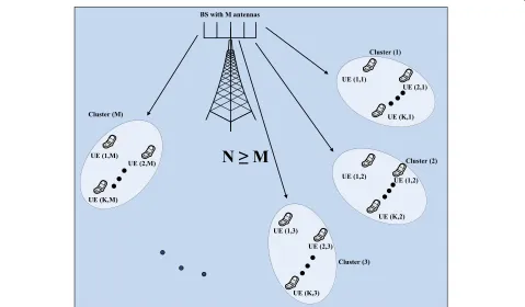
Consider a downlink MU-MIMO communication sce-nario where a BS with M transmit antennas is communi-cating with multiple UEs, each equipped with N receiving antennas. The served UEs are grouped into M clusters with K UEs in each cluster (Fig.1). In this work, we are considering scenarios in which the number of antennas at each user, namely N, is greater than the number of anten-nas equipped at the BS, namely M, that is to say N≥ M. This assumption is popular in some 5G scenarios such as ultra-dense small cells and cloud-radio access networks (C-RANs) [2]. Through this assumption we are trying to consider some of the realistic scenarios that all 5G com-munities and mobile communication companies agreed that it will be challenging in the near future. One of the main pillars upon which the next generation mobile net-works will based for achieving the 1000 times capacity scaling is the ultra-dense small-cell networks. In such net-work design, low-power low-cost small-cell BSs will be employed for mobile data offloading. So, it is very likely that it owns the same number of antennas as the UE or even less, given the rapid progress in increasing the capa-bilities of such UEs. Another network design that support our assumption is the C-RANs, in which UEs are served
by a small number of low-cost remote radio heads (RRHs) to reduce the fronthaul overhead [2].
The power-domain multiplexed signal of the users’ sig-nals in clustermis expressed as:
˜
sm=αm,1sm,1+αm,2sm,2+ · · · +αm,Ksm,K, (1)
where sm,k is the useful information signal to be trans-mitted to the kth user in the mth cluster, and αm,k is its corresponding NOMA PA coefficient. The signals to be transmitted by the BS in the downlink direction is firstly precoded using the beamforming filterV∈CM×M. Accordingly, the BS downlink transmitted signal can be written as:
x=V˜s, (2)
wherex=[x1x2· · ·xM]T ∈CM×1is the combined signal
transmitted from the BS to all users in different clusters,
withxm =
nel over which the BS transmits its signals is denoted as H = H1TH2TH3T· · ·HMT
T
∈ CMKN×M, where
Hm∈CKN×Mare the channels between the BS and users in clustermwhich are all Rayleigh fading channels, and the channel between the BS and thekth user in themth cluster is denoted as Hm,k. The vector s˜ represents the power-domain multiplexed signals for all the M clusters, which can be expressed in matrix form as:
˜
Accordingly, the signal received at thekthuser in themth
cluster is decoded usingum,kto give the detected signal as
uHm,kym,k=uHm,kHm,kVs˜+uHm,knm,k. (4)
Fig. 1One-cell downlink multi-user scenario composed of one BS equipped with M transmit antennas. The BS serves some users each equipped with N receive antennas and the users are grouped to M clusters with N≥M
transmitted to users belonging to the cluster of the user of interest, namely, the self-interference generated due to the implementation of the NOMA technique. On the other hand, the inter-user interference originated due to the transmission of signals to users who are not belonging to the same cluster of the considered user. Using the notation of intra-cluster and inter-cluster interference, the signal model in (5) can be detailed as:
uHm,kym,k=uHm,kHm,kvmαm,ksm,k
Desired Signal
+uHm,kHm,k K
j=1 j=k
vmαm,jsm,j
Intra-cluster Interference
+ uHm,kHm,k M
i=1 i=m
vis˜i
Inter-cluster Interference
+uHm,knm,k Noise
. (6)
where i,m ∈ {1, 2,· · ·,M}, and j,k ∈ {1, 2,· · ·,K}. Equation (6) shows how IA and NOMA schemes are inte-grated together to optimize the sum-rate of MU-MIMO network. The IA technique is applied through implement-ing the transmit and receive beamformers, um,k andvm. On the other hand, NOMA is applied through superim-posing the signals of all users in the cluster together using power domain multiplexing, and this is achieved through
careful evaluation of the PA coefficients. Our proposed algorithms will jointly optimize the beamforming vectors and the PA coefficients based on different objectives that are all related to the system sum-rate. The knowledge of the channel conditions is very critical for the implemen-tation of NOMA systems. Accordingly and without loss of generality, we will assume the channels such that the effective channel gains are ordered as follows:
uHm,1Hm,1vm2≥ · · · ≥uHm,KHm,Kvm2, (7) and according to the principles of NOMA technique, the PA coefficients of the users with in the mth cluster are ordered as follow:
α2
m,1≤ · · · ≤αm2,K. (8) Based on (6), the signal-to-interference-plus-noise power (SINR) ratio for theKthuser, the user with smallest effec-tive channel gain in themthcluster, is given by
SINRm,K= (9)
uHm,KHm,Kvm
2
α2
m,K K−1
j=1
uHm,KHm,Kvm
2
α2
m,j+ M
i=1
i=m
uHm,KHm,Kvi
2
+um,K2 1ρ
,
whereρrefers to the transmit SNR. According to the
princi-ples of the NOMA technique, thekthuser,∀1<k<Kin the
with poorer channel conditions first before decoding its own message. Accordingly, the messagesm,j,K≥j≥(k+1), can be
detected atkthuser in themthcluster with SINR expressed as:
SINRjm,k= (10)
observation of thekthuser. This message can be decoded
suc-cessfully only when meeting the condition log(1+SINRjm,k) >
Rm,j, withRm,jdenoting thejthuser target data rate. The
oper-ation of the SIC technique will continue until the kth user
decodes its own message with SINR equals SINRkm,k. The first user in themthcluster, which is the user with largest effective
channel gain, is responsible for decoding all the messages of other users in the cluster . If it is successful, it can decode its own message with SINR equals
SINR1m,1= u
IA and PA techniques are both used to improve the sum-rate for many different wireless communication scenarios [25]. However, up to the best of our knowledge, the study of combining IA approach with PA technique in NOMA-based MU-MIMO environment is not sufficiently conducted. In our proposed framework, the design of the PA scheme depends mainly on the IA strategy to be employed. So, the design of the precoding and decoding filters based on the principles of IA is accomplished first and consequently the PA strategies will be achieved. In the following section, the problem formulation for designing the IA-based precoding and decoding matrices for different IA approaches will be manipulated. This will be fol-lowed with the PA design problem which will be addressed in Section4.
3
IA solutions for multi-user MIMO-NOMA
The design of the precoding and decoding filters for all the network nodes depends on the objective of the IA design pro-cess and the availability of the CSI. In this section, we consider the case where no global CSI available at the BS followed by the case with full global CSI available at the BS and IA transceivers design in each case. In our designs for NOMA-based MU-MIMO system with full global CSI at the BS, the considered objectives of IA technique are SINR maximiza-tion approach (max-SINR), interference leakage minimizamaximiza-tion approach (MIL), and sum-rate maximization approach (Max-SR). The derivations and details of each approach are discussed in the below subsections.
3.1 The case with no CSI available at the BS
In the proposed framework, the IA technique is responsible for removing the inter-cluster interference leaving the intra-cluster
interference to the SIC technique implicitly implemented in the NOMA design. Accordingly, the IA conditions that guar-antee the removal of inter-cluster interference are expressed as follows:
uHm,kHm,kvi=0, ∀i=m (12)
The availability of CSI at the BS can be considered as a great system overhead. Accordingly, designing IA precoding and decoding filters with no CSI available at the BS, however, it is non-optimal, but it is considered in many practical scenarios because of its reduced system overhead of acquiring the global CSI from all the system nodes. One of the possible solutions to (12) is to chooseV, asV=IM. ChoosingVin this form means
that the BS broadcasts user messages without any processing, which reduces the overhead due to handshaking messages in acquiring and forwarding CSI in the network. Accordingly, the decoding filters can be evaluated by substituting in (12) as:
uHm,khi,mk=0, ∀i=m (13)
wherehi,mkis theithcolumn ofHm,k. As a result of that, the IA
constraints at thekthuser in themthcluster can be written as:
uHm,kh1,mk· · ·hm−1,mkhm+1,mk· · ·hM,mk
By using the precoding and decoding matrices derived in this section, the inter-cluster interference will be eliminated, and the SINR forKthuser in themthcluster will be given by:
SINRjm,K =
successfully detected at thekthuser,K>k>1 with SINR:
SINRjm,k=
The SIC scheme implemented with NOMA technique will take care of the remaining intra-cluster interference.
Specifi-cally, for the usersk, andj, withK ≥ j ≥ k+1 ≥ 1, when
the messagesj,1is successfully detected at thekthuser, it will
be removed from thekthuser’s superimposed received signal,
and SIC scheme will continue working until its own message is received with SINR equals SINRkm,k. The evaluation of the optimum values of the PA coefficients will be discussed in Section4.
3.2 The case with full global CSI available at the BS
the BS to determine the optimal IA transceiver design for all users and the BS. Specifically, we explain how to design the optimal IA precoder and decoder for each user-BS pair using the MIL, Max-SINR, and Max-SR approaches through solv-ing their respective optimization problems. The general idea of using IA in our scenario is to align the unwanted received signals at the user of interest (the power multiplexed signals assigned to other clusters), into an interference subspace and reducing its projection within the desired signal subspace (the power multiplexed signals of users in its cluster). For example, for thekthuser in themthcluster, the IA constraints are:
rankuHm,kHm,kvm=M, (18)
uHm,kHm,kvi=0, ∀i=m (19)
∀m∈ {1, 2,· · ·,M}&k∈ {1, 2,· · ·,K}
IA is used to align the effect of all other clusters by consid-ering them as interference and directing their effects into the interference subspace. This will leave each user only with the effect of its cluster-partners which can be dealt with the SIC technique which is already the core of the NOMA radio access technology.
3.2.1 Interference leakage minimization approach
As the name implies, this approach targets minimizing the other clusters-interference signals deliberated to the desired signal subspace at the user, and the process can be accom-plished for the whole cluster at one shot by solving the cor-responding optimization problem. The optimization problem corresponding to themthcluster is formulated as:
minimize
is the total interference leakage
deliberated to the useful subspace of cluster m, and Qm is
the interference covariance matrix for themthcluster,Q
m =
lem can be solved by fixing a subset of variables (either Um
or V), and then optimize for the others, then alternate the
roles between the fixed constant variables and the optimiza-tion variables. This technique tries to minimize interference leakage by alternatively optimizing the IA beamforming fil-ters. Thus, at the BS, suppose the transmission is carried out in a specific communication direction, the optimization prob-lem (20) is subject toUmUHm = IN, where we optimize for
the decoding filtersUm. On the other hand, when the
com-munication direction is reversed, the precoding and decoding filters are interchanged, and the optimization problem is now
constrained toVVH = IMinstead. If we denotedmasdm =
min(M, N), the resulted optimization problem in each
direc-tion can be solved iteratively using alternative minimizadirec-tion
by finding thedm eigenvectors corresponding to smallestdm
number of eigenvalues of the interference covariance matrix
Qm at each iteration [8]. Therefore, thedm columns of Um
are given by:
U[md]=νd[Qm] , ∀d= {1,· · ·,dm} (21)
whereνd[A] refers to the eigenvectors corresponding to thed
smallest eigenvalues ofA.
3.2.2 Maximum-SINR approach
Another criteria that typically used as an objective to the IA design is the SINR-maximization approach. Specifically, the IA transceiver filters can be designed to maximize the SINR instead of only minimizing the interference leakage, where the MIL approach gives no attempt to maximize the desired signal power within the desired signal subspace. In other words, the MIL approach does not depend at all on the chan-nels through which the desired signal arrives at the intended receiver. According to [8], the IA filters are obtained by:
um,k=
The last criteria and optimization problem that is used to design the IA transceiver filters at the BS is the sum-rate max-imization. The goal is to design the optimum transceivers that maximize the sum-rate.
3.2.3 Sum-rate maximization approach
With this approach, we want to obtain the optimum transceiver filters that maximize the total system sum-rate. Accordingly, the optimization problem that will be implemented to evaluate the IA transceivers have the following form:
minimize
whereRm,krepresents the mutual information rate between the
BS and thekthuser in themthcluster, and it is given by:
For solving the optimization problem in (24), we will use an iterative algorithm based on Riemannian optimization method
standard euclidean optimization by formulating the optimiza-tion problem over smooth manifolds instead of the standard
euclidean space [27–29]. The update rule for the IA
itera-tive algorithm that based on maximizing the sum-rate is given by the Riemannian optimization over the Grassmann mani-fold and based on geodesics of a straight line in the euclidean space to the manifold. The update rule of the decoding matrix
Um, m∈ {1, 2,· · ·,M}over the Grassmann manifoldGrwith
gradient descent method is expressed as [27]:
Unm+1=φGr
mann manifoldsGr,Um ∈Gr, in the direction of the gradient
of the function Rsum, expressed as “gradUmRsum”, and μ is
the step size. The gradient, gradUmRsum, on the Grassmann
manifoldGris computed as:
gradGrU
mRsum=Rsum(Um)−UmU H
mRsum(Um). (28)
The natural gradient of Rsum(Um), expressed asRsum(Um)
is a real valued function. However,Umis a matrix whose
com-ponents are complex, so according to [30], the gradient can be evaluated as
with respect tox. The matricesXandYare expressed as:
Xm=I+
The update rule for the iterative algorithm that computes
the decoding matricesUmis derived by substituting (28) and
(30) in (27).
4
The proposed joint PA and IA methods
In this section, the applied user clustering models are first explained; then, the concepts and details of the proposed PA algorithms are manipulated. Finally, the proposed joint PA and IA algorithms is proposed based on both the clustering and PA concepts.
4.1 User clustering models
User pairing is demonstrated to be very beneficial for the implementation of the NOMA technique in downlink MU scenarios [2]. In a similar fashion, we will illustrate the gain of grouping the users into clusters in the case of downlink NOMA-based MU-MIMO system with the implementation of joint IA and PA optimization. The clustering process and its optimization is beyond the scope of this article. However, we will implement two extreme models for user clustering to prove the importance of using it, in terms of sum-rate, when dealing with IA and PA for downlink NOMA-based MU-MIMO
sys-tems. The first model depends on grouping theK users with
the best channels together in the first cluster, then the following
Kbest channels’ users are grouped within the second cluster,
and so on. On the other hand, the second model depends on
distributing theMusers with best channel gains, one in each
of theM clusters, then the followingMbest channels is
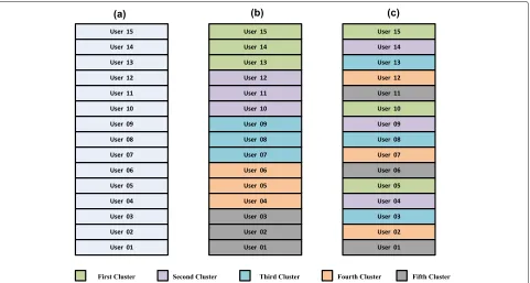
dis-tributed in the same fashion, and so on. Figure2illustrates the concepts of the two clustering models. In the following dis-cussion, we will refer to the first and second models as the best-with-best and the best-with-poor models, respectively. In both clustering models, the user with the best channel gain can be considered as the cluster head.
4.2 Power allocation approach
We consider that the downlink NOMA-based MU-MIMO sys-tem is divided into clusters and the beamforming process is designed such that a single beam used to send all the data mes-sages to their respective users within a specific cluster. Since each cluster contains the same number of users and their chan-nel gains follow the same random distribution, we assume the power budget of the BS will be divided equally between all the clusters. If we assume that the power budget of the BS is
denoted as PBS, subsequently, this power is allocated equally
between the M clusters with each cluster allocated an amount equal to(PBS/M). The power budget for each cluster will be allocated among the scheduled users within the cluster accord-ing to the principles of the NOMA technique. For the PA among the users within the cluster, the sum-rate is maximized under cluster power budget constraints, minimum user sum-rate (as quality of service metric) constraints, and constraints related to the implementation of SIC technique, i.e. minimum power differences among NOMA received signals as illustrated
in [31]. The PA strategy will be applied separately with each
cluster. Without loss of generality, we assume that the effec-tive channel gains of the users within the mthcluster satisfying
um,1Hm,1Vm > um,2Hm,2Vm > · · · > um,kHm,kVm > · · · >um,KHm,KVm. Additionally, we refer to the minimum
sum-rate values that must be guaranteed by all users within the cluster asRm,1,Rm,2,· · ·,Rm,K whereRm,k > 0, ∀mand∀k.
Fig. 2The clustering models for downlink multi-user MIMO-NOMA with joint IA and PA optimization:aThe users’ effective channel gains are ordered in descending fashion.bThe users are clustered according to the best-with-best model.cThe users are clustered according to the best-with-poor model
use the whole system bandwidthBWto serve its users. The PA
optimization problem for the users within themthcluster can
be reformulated as:
wherePthdenotes the threshold minimum received power
dif-ference between users’ signals required for carrying out the SIC technique. The previous optimization problem is similar in notation to those mentioned in [31,32], and accordingly the closed form solution presented in [32] can be applied directly
to solve the optimization problem in (31). LetBandCdenote
the complementary set of users in themthcluster that meet the minimum sum-rate for the users and SIC visibility constraints,
respectively. The optimal PA for the first user within themth
cluster is given by:
α2
Additionally, the PA coefficient for thekthuser, withk =1,
within themthcluster can be expressed as:
• Ifk∈B
The detailed steps for the proposed joint IA and PA framework based on different IA approaches are given in Algorithms 1, 2, and 3.
Algorithm 1 The MIL based IA approach for NOMA-based MU-MIMO systems
1: Initialize the beamforming filters, Vm, ∀ m ∈ {1, 2,· · ·,M}, for the clusters with unitary matri-ces, and initialize the PA coefficients αm,k, ∀ m ∈ {1, 2,· · ·,M}, andk∈ {1, 2,· · ·,K}while keeping the NOMA PA constraints.
2: Calculate the interference covariance matrix for each cluster,m, as:
3: Compute the decoding matrices that minimize the
interference leakage due to undesired messages,Um, according to (21).
4: Compute the beamforming matrices using Steps 2
and 3, where we assume a reverse communication direction and initializing the decoding matrices by the values obtained in the previous step and replace the decoding matrices with the beamforming matrices and vice-versa.
5: Update the PA coefficients for all users using (32),
(33), and (34).
6: Repeat the Steps from 2 to 5 until the algorithm
convergences.
7: Distribute the calculated transceiver filters, and the
PA coefficients to the corresponding users.
Note that the PA coefficients are initialized in all the three algorithms asαm,k=1/K. Each of the algorithms is dependent
on a specific criteria for achieving the IA conditions as
explained in Subsection3.2. All these algorithms rely on the
availability of CSI, and all apply the same power allocation
algorithm introduced in Section4. Since the evaluation of the
Algorithm 2 The Max-SINR based IA approach for NOMA-based MU-MIMO systems
1: Initialize the beamforming filters, Vm, ∀ m ∈ {1, 2,· · ·,M}, for the clusters with unitary matri-ces, and initialize the PA coefficients αm,k, ∀ m ∈ {1, 2,· · ·,M}, andk ∈ {1, 2,· · ·,K}while keeping the NOMA PA constraints.
2: Calculate the matrixBm,kfor each user using (23).
3: Compute the decoding matrices that maximize the SINR,Um, according to (22).
4: Compute the decoding matrices using Steps 2 and 3, where we assume a reverse communication direc-tion and initializing the decoding matrices by the values obtained in the previous step and replace the decoding matrices with the beamforming matrices and vice-versa.
5: Update the PA coefficients for all users using (32),
(33), and (34).
6: Repeat the Steps from 2 to 5 until the algorithm
convergences.
7: Distribute the calculated transceiver filters, and the
PA coefficients to the corresponding users.
Algorithm 3The Max-SR based IA approach for NOMA-based MU-MIMO systems
1: Initialize the beamforming filters, Vm, ∀ m ∈ {1, 2,· · ·,M}, for the clusters with unitary matrices, the step sizeμwith 0.1, and initialize the PA coeffi-cientsαm,k, ∀m∈ {1, 2,· · ·,M}, andk∈ {1, 2,· · ·,K} while keeping the NOMA PA constraints.
2: Calculate the matrixBm,kfor each user using (23).
3: Compute the decoding matrices that maximize the
SINR,Um, according to (22).
4: Update the beamforming matrices, Vm along the geodesic over the Grassmann manifold in the direc-tion given by the gradient of Rsum using (27) and
(30).
5: Update the PA coefficients for all users using (32), (33), and (34).
6: Update the optimization step sizeμ=μ×0.95.
7: Repeat the Steps from 2 to 6 in the reverse
communi-cation direction until the algorithm convergences.
8: Distribute the calculated transceiver filters, and the
PA coefficients to the corresponding users.
matrices Qm, andBm,k depends on the PA coefficients, the
in details in Section 4. It is worth noting that the proposed iterative IA techniques are carried out offline as we are assum-ing stationary block fadassum-ing channels, which remains constant during the transmission process. Accordingly, the complexity analysis of the algorithms is not as important as the gain in the system sum-rate.
5
Simulation results and discussion
In this section, we introduce simulation results to illustrate the sum-rate improvement resulted due to joint optimization of IA transceivers and PA coefficients for downlink NOMA-based MU-MIMO systems. Additionally, the simulation results for the proposed NOMA-based MU-MIMO system with joint IA and PA optimization is compared with those of the conventional NOMA-based MU-MIMO as well as the OMA-based MU-MIMO systems. The channels between the BS and the users are all assumed to be Gaussian distributed Rayleigh fading with zero mean and unit variance in addition to the shadowing and the pathloss effects with parameters
as mentioned in [32]. Additionally, we assume that perfect
full global CSI is available at the BS. In other words, the BS owns a copy of the channel between it and each user in the system [8–18,32]. The simulation results are obtained through averaging the measurements over 5000 channel realizations. For the proposed NOMA-based MU-MIMO network with clustering model employed, we have assumed that the number of clusters in the system equals the number of antennas at the BS, and all clusters have the same size (number of users in the cluster). A list of all the simulation parameters used
in evaluating our results are in Table 1. The algorithms that
will be involved in the comparison are MIL-IA implemented in OMA-based MU-MIMO system (MIL-IA-MIMO-OMA), MIL-IA implemented in conventional NOMA-based
MU-MIMO system (MIL-IA-Conv-MIMO-NOMA), MIL-IA
implemented in the proposed NOMA-based MU-MIMO system (MIL-IA-Proposed-MIMO-NOMA), Max-SINR-IA implemented in OMA-based MU-MIMO system
(Max-SINR-IA-MIMO-OMA), Max-SINR-IA implemented in
conventional NOMA-based MU-MIMO system
(Max-SINR-IA-Conv-MIMO-NOMA), Max-SINR-IA implemented in
the proposed NOMA-based MU-MIMO system (Max-SINR-IA-Proposed-MIMO-NOMA), Max-SR-IA implemented in OMA-based MU-MIMO system (Max-SR-IA-MIMO-OMA), Max-SR-IA implemented in conventional NOMA-based
MU-MIMO system (Max-SR-IA-Conv-MIMO-NOMA),
Max-SR-IA implemented in the proposed NOMA-based MU-MIMO (Max-SR-IA-Proposed-MIMO-NOMA),
SVD-based IA implemented in OMA-based MU-MIMO (SVD-IA-MIMO-OMA), SVD-based IA implemented in conventional NOMA-based MU-MIMO system introduced
in [24] (SVD-IA-Conv-MIMO-NOMA in [24]), SVD-based
IA implemented in the proposed NOMA-based MU-MIMO system (SVD-IA-Proposed-MIMO-NOMA), and the con-ventional NOMA-based MU-MIMO system without IA
(Conv-NOMA without IA [23]).
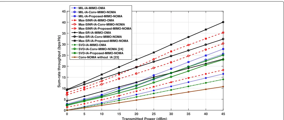
Figure3shows the variation of the sum-rate versus the
trans-mitted power, Ptr, with different IA approaches for the
pro-posed NOMA-based MU-MIMO as well as the conventional
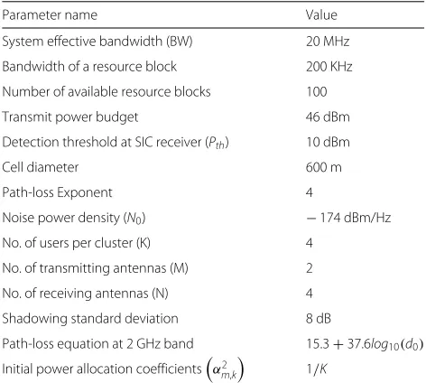
Table 1Simulation parameters
Parameter name Value
System effective bandwidth (BW) 20 MHz
Bandwidth of a resource block 200 KHz
Number of available resource blocks 100
Transmit power budget 46 dBm
Detection threshold at SIC receiver (Pth) 10 dBm
Cell diameter 600 m
Path-loss Exponent 4
Noise power density (N0) −174 dBm/Hz
No. of users per cluster (K) 4
No. of transmitting antennas (M) 2
No. of receiving antennas (N) 4
Shadowing standard deviation 8 dB
Path-loss equation at 2 GHz band 15.3+37.6log10(d0)
Initial power allocation coefficientsα2
m,k
1/K
MIMO-NOMA and MIMO-OMA systems. In these simula-tion results, we have assumed that users having the same order within the clusters will be assigned the same minimum
sum-rate value, which is inserted in (31) as the minimum sum-rate
constraint, mathematically speaking, we assume that Rm−1,k=
Rm,k = Rm+1,k, ∀m ∈ {1, 2,· · ·,M}. It is obvious from the
results that, the IA approach that depends on maximizing the system sum-rate over the Grassmann manifold outperforms both the MIL and Max-SINR approaches with both the pro-posed and the conventional systems. The cause behind that fact is that the sum-rate maximization approach considers optimiz-ing all the Shanonn’s capacity equation’s parameters, namely the spatial DoFs, desired signal power, and the undesired inter-ference power, while other approaches consider optimizing only one or two of these parameters. Additionally, the proposed NOMA-based MU-MIMO system that employs clustering, IA,
and optimum PA obtained by solving (31) provides the most
higher sum-rate performance, followed by the conventional NOMA-based MIMO system, and the OMA-based MU-MIMO system provides the worst performance in the compar-ison. Moreover, it is obvious that all the proposed algorithms outperform the state-of-the-art algorithms [23,24].
Figure4shows the effect of choosing the clustering model
within the proposed NOMA-based MU-MIMO system. In our
work, we employed the two clustering models shown in Fig.2.
Fig. 3The transmitted power Ptrin (dBm) versus the sum-rate in (bits/sec/Hz) for the proposed MIMO-NOMA approach (With joint IA and PA), in
comparison with the conventional MIMO-NOMA approach (no clustering and the power distributed equally between users), and the case of IA with MIMO-OMA
the cluster. Another important observation is that the supe-riority of the with-poor clustering model than the best-with-best clustering model is guaranteed with any of the IA approaches. At a transmitted power of 35 dB, the proposed MIMO-NOMA with Max-SR IA approach achieves around 11 (bits\sec\Hz) more sum-rate with best-with-poor clustering model than with best-with-best model. Similar conclusions can be reported with other IA approaches at different transmitted power levels.
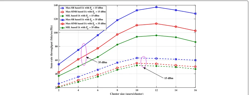
Figure5shows the effect of the cluster size, defined as the
number of users per cluster, on the system sum-rate. The sum-rate grows almost linearly with the cluster size for all IA
approaches until reaching a specific cluster size, 10 and 12 users at transmission power levels 15dBm and 35dBm, respec-tively. After that, the sum-rate begins to decay due to the lower efficiency of the SIC technique and accordingly the growth of intra-cluster interference. In other words, the sum-rate for the NOMA-based MU-MIMO system grows with the cluster size as long as the system meets the constraint of minimum received power differences among the users. Once the sys-tem violates this constraint, the SIC technique provides lower efficiency in canceling the intra-cluster interference and the sum-rate begins to decrease. This behavior is common among all IA approaches with different transmission powers.
Fig. 5The cluster size in (users/cluster) versus the sum-rate in (Bits/sec/Hz) for different IA approaches with the proposed MIMO-NOMA with transmitted power of 15dBm, and 35dBm
6
Conclusions
In this article, we have studied the application of different IA approaches to downlink NOMA-based MU-MIMO systems. Specifically, we have proposed a joint IA and PA framework for maximizing the sum-rate of the NOMA-based MU-MIMO system under different approaches of IA. It turns out from the simulation results that IA is still an excellent scheme for access-ing the maximum DoFs of the next generation NOMA-based networks. Additionally, user clustering is proven to be a crit-ical step for the joint optimization of the PA coefficients and IA transceivers in NOMA-based MU-MIMO systems. Finally, we concluded that accompanying the NOMA access technol-ogy with IA combined with optimum PA algorithm can be considered as a key solution for achieving the capacity scaling targeted by next generation 5G networks. As a future work, the performance of the proposed algorithms would be stud-ied under both instantaneous and statistical CSI. Moreover, the performance of the IA-based transceivers in NOMA-based MU-MIMO system will be investigated with partial CSI.
Abbreviations
BS: Base-station; CSI: Channel state information; C-RAN: Cloud-radio access networks; DoFs: Degrees of freedom; IA: Interference alignment; IC: Interference channel; MU-MIMO: Multi-user multiple-input multiple-output; NOMA: Non-orthogonal multiple access; OMA: Orthogonal multiple access; PA: Power allocation; QoS: Quality of service; RRH: Remote radio heads; SIC: Successive interference cancellation; SINR: Signal to interference plus noise ratio; SNR: Signal to noise ratio; SVD: Singular value decomposition; UE: User equipment; 5G: Fifth generation
Acknowledgements
The authors would like to thank the anonymous reviewers for their insightful comments.
Funding
The EURASIP Journal on Wireless Communications and Networking supports the publication of this article.
Authors’ contributions
All authors discussed the experiments; MR performed the experiments and wrote the paper. LH and PZ have made some useful comments on the paper. All authors have read and approved the final manuscript.
Competing interests
The authors declare that they have no competing interests.
Publisher’s Note
Springer Nature remains neutral with regard to jurisdictional claims in published maps and institutional affiliations.
Author details
1Multi-dimensional Signal Processing Lab., College of Information
Engineering, Shenzhen University, Shenzhen, China.2Department of Electronics and Communication Engineering, Faculty of Electronic Engineering, Menoufia University, Shibin Al-Kawm 21974, Egypt.
Received: 5 February 2018 Accepted: 8 August 2018
References
1. L. Dai, B. Wang, Z. Ding, Z. Wang, S. Chen, L. Hanzo, A Survey of Non-Orthogonal Multiple Access for 5G. IEEE Surv. Tutor. Accessed on 8 July 2018. [Online]. availablehttps://doi.org/10.1109/COMST.2018.2835558 2. Z. Ding, F. Adachi, V. Poor, The application of MIMO to non-orthogonal
multiple access. IEEE Trans. Wirel. Commun.15(1), 537–552 (2016) 3. Z. Ding, X. Lei, G.K. Karagiannidis, R. Schober, J. Yuan, V.K. Bhargava, A
Survey on Non-Orthogonal Multiple Access for 5G Networks: Research Challenges and Future Trends. IEEE J. Sel. Areas Commun.35(10), 2181–2195 (2017)
4. S. Timotheou, I. Krikidis, Fairness for non-orthogonal multiple access in 5G systems. IEEE Signal Sig. Process.22(10), 1647–1651 (2015)
5. L. Dai, B. Wang, Y. Yuan, S. Han, I. Chih-lin, Z Wang, Non-orthogonal multiple access for 5G: solutions, challenges, opportunities, and future research trends. IEEE Commun. Mag.53(9), 74–81 (2015)
6. L. Lv, Q. Ni, Z. Ding, J. Chen, Application of non-orthogonal multiple access in coopertaive spectrum-sharing networks over Nakagami−m fading channels. IEEE Trans. Veh. Technol.66(06), 5506–5511 (2016) 7. S. Islam, M. Zeng, O. Dobre, K. Kwak, Resource Allocation for Downlink
NOMA Systems: Key Techniques and Open Issues. IEEE Wirel. Commun. 25(2), 40–47 (2018)
8. K. Gomadam, V.R. Cadambe, S.A. Jafar, A distributed numerical approach to interference alignment and applications to wireless interference networks. IEEE Trans. Inf. Theory.57(06), 3309–3322 (2011) 9. O. El Ayach, S.W. Peters, R.W. Heath Jr., The feasibility of interference
10. T. Ying, W. Feng, G. Liu, Space-Time Interference Alignment: DoF of Two-User MIMO X-Channel with Alternating CSIT. IEEE Commun. Lett. 21(5), 1167–1170 (2017)
11. X. Jing, L. Mo, H. Liu, C. Zhang, Linear Space-Time Interference Alignment for K-User MIMO Interference Channel. IEEE Access.6, 3085–3095 (2017) 12. M. Rihan, M. Elsabrouty, O. Muta, H. Furukawa, inIEEE vehicular technology
conference (VTC Spring). Interference alignment with limited feedback for macrocell-femtocell heterogeneous networks (IEEE, Glasgow, 2015), pp. 1–5 13. M. Rihan, M. Elsabrouty, O. Muta, H. Furukawa, Interference mitigation
framework based on interference alignment for femtocell-macrocell two tier cellular systems. IEICE Trans. Commun.E98-B(03), 467–476 (2015) 14. T.T. Vu, H.H. Kha, O. Muta, M. Rihan, Energy-efficient interference
mitigation with hierarchical partial coordination for MIMO heterogeneous networks. IEICE Trans. Commun.E100-B(06), 3247–3255 (2016) 15. H. Men, N. Zhao, M. Jin, J. M. Kim, Optimal transceiver design for
interference alignment based cognitive radio networks. IEEE Commun. Lett.19(08), 1442–1445 (2015)
16. B. Guler, A. Yener, Selective interference alignment for MIMO cognitive femtocell networks. IEEE J. Sel. Areas Commun.32(03), 439–450 (2014) 17. S. Cho, K. Huang, D.K. Kim, V.K.N. Lau, H. Chae, H. Seo, B. Kim,
Feedback-topology designs for interference alignment in MIMO interference channels. IEEE Trans. Sig. Process.60(12), 6561–6575 (2012) 18. O. El Ayach, S.W. Peters, R.W. Heath Jr., The practical challenges of
interference alignment. IEEE Wirel. Commun.20(01), 35–42 (2013) 19. N. Zhao, F. Richard Yu, M. Jin, Q. Yan, V.C.M. Leung, Interference
Alignment and Its Applications: A Survey, Research Issues and Challenges. IEEE Commun. Surv. Tutor.18(3), 1779–1803 (2016)
20. Y. Fadlallah, K. Amis, A. Aissa-El-Bey, R. Pyndiah, Interference Alignment for a multi-user SISO interference channel. EURASIP J. Wirel. Commun. Netw. https://doi.org/10.1186/1687-1499-2014-79
21. Q. Sun, S. Han, Z. Xu, S. Wang, I. Chih-Lin, Z. Pan, inIEEE wireless communications and networking conference (WCNC). Sum rate
optimization for MIMO non-orthogonal multiple access systems (IEEE, Istanbul, 2015), pp. 747–752
22. Z. Ding, R. Schober, H.V. Poor, A general MIMO framework for NOMA downlink and uplink transmission based on signal alignment. IEEE Trans. Wirel. Commun.15(06), 4438–4454 (2016)
23. Y. Liu, G. Pan, H. Zhang, M. Song, On the capacity comparison between MIMO-NOMA and MIMO-OMA. IEEE Access.04, 2123–2129 (2016) 24. Z.Q. Al-Abbasi, D.K.C. So, J. Tang, inIEEE international communications
conference (ICC)- wireless communications symposium. Resource Allocation for MU-MIMO non-orthogonal multiple access (NOMA) system with interference alignment (IEEE, Paris, 2017), pp. 1–6
25. H. Sung, S.H. Park, K.J. Lee, I. Lee, Linear precoder designs for K user interference channels. IEEE Trans. Wirel. Commun.9(01), 291–301 (2010) 26. I. Santamaria, O. Gonzalez, R. Heath, S. Peters, inIEEE GLOBECOM.
Maximum sum rate interference alignment algorithms for MIMO channels (IEEE, Miami, 2010), pp. 1–6
27. T.E. Brudan, J. Eeiksson, V. Koivunen, Steepest descent algorithms for optimization under unitary matrix constraint. IEEE Trans. Sig. Process. 56(03), 1134–1147 (2006)
28. Y. Nishimori, S. Akaho, S. Abdallah, M. Plumbley, inIEEE conference on acoustics, speech, and signal processing. Flag Manifolds for Subspace ICA Problems (IEEE, Honolulu-HI-USA, 2017)
29. A. Edelman, T.A. Arias, S.T. Smith, The Geometry of algorithms with orthogonality constraints. SIAM J. Matrix Anal. Appl.20(2), 303–353 (1998) 30. S. Ye, R.S. Blum, Optimized signaling for MIMO interference systems with
feedback. IEEE Trans. Sig. Process.51(11), 2839–2848 (2003)
31. M.S. Ali, E. Hossain, D.I. Kim, Non-orthogonal multiple access (NOMA) for downlink multiuser MIMO systems: User clustering, beamforming, and power allocation. IEEE Access J. Phys. Mediu. Access Control. Layer Adv. 5G Wirel. Netw.05, 565–577 (2016)