Breakpoint Tuning in DCT-Based Nonlinear
Layered Video Codecs
Pedro Cuenca
Departamento de Inform´atica, Escuela Polit´ecnica Superior de Albacete, Universidad de Castilla-La Mancha, Campus Universitario, 02071 Albacete, Spain
Email:[email protected]
Luis Orozco-Barbosa
Departamento de Inform´atica, Escuela Polit´ecnica Superior de Albacete, Universidad de Castilla-La Mancha, Campus Universitario, 02071 Albacete, Spain
Email:[email protected]
Francisco Delicado
Departamento de Inform´atica, Escuela Polit´ecnica Superior de Albacete, Universidad de Castilla-La Mancha, Campus Universitario, 02071 Albacete, Spain
Email:[email protected]
Antonio Garrido
Departamento de Inform´atica, Escuela Polit´ecnica Superior de Albacete, Universidad de Castilla-La Mancha, Campus Universitario, 02071 Albacete, Spain
Email:[email protected]
Received 31 August 2003; Revised 2 February 2004
Many studies have been conducted to evaluate the benefits of using layered video coding schemes as a means to improve the robustness of video communications systems. In this paper, we study a frame-aware nonlinear layering scheme for the transport of a DCT-based video over packet-switched networks. This scheme takes into account the relevance of the different elements of the video sequence composing the encoded video sequence. Throughout a detailed study over a large set of video streams, we show that by properly tuning the encoding parameters, it is feasible to gracefully degrade or even maintain the video quality while reducing the amount of data representing the video sequence. We then provide the major guidelines to properly tune up the encoding parameters allowing us to set the basis towards the development of more robust video communications systems.
Keywords and phrases:DCT, nonlinear layering video coding, video communications, video quality.
1. INTRODUCTION
Recent developments in the areas of video coding and compression techniques are enabling the deployment of computer-based video communications systems. In a video communications system, it is essential to count with a reli-able support that is reli-able to guarantee the timely and relireli-able transport of a video stream. The video process must how-ever incorporate the essential elements to react to potential changes in the service provided by the network.
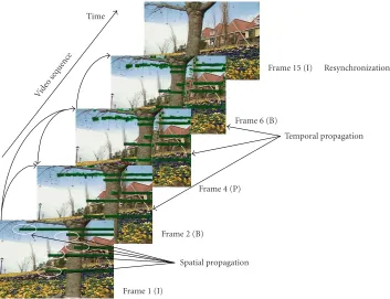
The fact that most video coding schemes use compres-sion techniques makes video communications applications very vulnerable to losses. In the absence of any error control mechanism, the loss of video data causes the loss of informa-tion up to the next resynchronizainforma-tion point (e.g., slice
Frame 1 (I)
Spatial propagation Frame 2 (B)
Frame 4 (P)
Temporal propagation Frame 6 (B)
Frame 15 (I) Resynchronization Time
Vide ose
quen ce
Figure1: Spatial and temporal propagation phenomena.
That is to say, the impairment will propagate through the whole group of pictures (GOP) associated to the impaired reference frame. This effect is known astemporal loss propa-gation(Figure 1). These phenomena will affect the quality of the video signal, and without adequate controls to locate the propagation of the impairments, the quality of the services (QoSs) may fall below acceptable levels [1].
Most techniques used for the reliable transfer of video over communications networks can be classified into two classes [2]: error-resilient techniques and regeneration tech-niques. The former are implemented in the codecs as well as in the switching elements of the networks, while the lat-ter are implemented by the decoder by making use of redun-dancies present in the encoded stream to regenerate the miss-ing pieces of information. Both techniques can be combined to develop structured error-resilient video communications systems [3].
The regeneration techniques can be reinforced using lay-ered encoding. Under a laylay-ered encoding scheme, the most relevant elements of the video sequence are included in a
base layer, while less relevant pieces of information are put into a second level, also denominatedenhancement layer. Ac-cording to their relevance, the base layer receives a high-priority treatment while the other layer is delegated to a sec-ond plane. Thebase layerprovides by itself a minimum ac-ceptable quality video image. One of the main advantages is that this type of encoding scheme can be applied to all discrete cosine transform (DCT)-based encoding scheme, such as H.261, H.263, MPEG-1, MPEG-2, MPEG-4, H.264, among others [4,5,6,7,8,9,10,11,12,13,14,15,16,17].
Video encoders incorporating these features could be used to develop QoS-aware video communications systems. For instance, such video encoders could adapt its encoding pa-rameters in response to a congestion signal from the net-work. In this way, the encoders could temporally reduce the video generation rate while maintaining a minimum accept-able video quality. However, the effectiveness of such schemes will highly depend on the way the encoding parameters are set up.
HP LP HP-LP
Breakpoint
DCT DC size DCT DC differ. coeffiDCTcient 1 coeffiDCTcient 2 coeffiDCTcient 3 coeffiDCTcient 4 · · · EOB MB addr.
increament MB
type Motiontype DCTtype q-scale Motionvectors CBP Block Block Block · · · Block Slice
header Breakpoint q-scale MB MB MB MB · · · MB
Picture header
Picture
cod. ext. Slice Slice Slice · · · Slice
GOP
header Picture Picture Picture · · · Picture
Sequence header
Sequence ext.
Sequence dis. ext.
Sequence
sca. ext. GOP GOP · · · GOP
Sequence Sequence Sequence
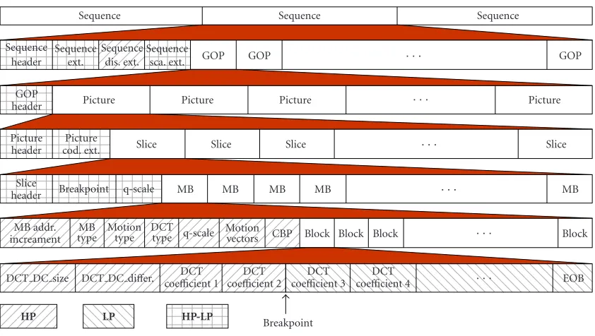
Figure2: Implementation of DCT-based layered video codecs.
2. DCT-BASED LAYERED VIDEO CODECS
Various DCT-based layered video coding schemes have been proposed in the literature in order to improve the robustness of video communications applications [3,18,19,20,21]. The main idea is based on the same principle: the insensibility of the human visual system to high-frequency components of the video signal. Under these schemes, the low-frequency DCT coefficients together with other relevant information are transmitted at a high-priority (HP) level, also denomi-nated base layer. High-frequency DCT coefficients and other less relevant information are then transmitted at a lower-priority (LP) level, also denominated enhancement layer. If parts of the enhancement layer are lost, they are simply re-placed by zeros and the image reconstructed using the base layer and the dummy enhancement layer—though somewhat distorted—may be acceptable.
This scheme can be easily adapted to transmission net-works which support different QoS levels as ATM, Hiper-lan/2, 802.11a/b networks or to network protocols which support different QoS levels, such as IntServ, Diffserv, and MPLS [22, 23, 24, 25, 26, 27, 28]. By using these layered video codecs, a correct transmission of the most important information of the video signal can be somehow guaranteed [29,30]. Furthermore, the base layer can be designed so that it can provide by itself a minimum acceptable image quality in situations in which the enhancement layer is completely lost. In these cases, temporary reduction of video quality tar-get and graceful quality degradation is obtained.
2.1. Implementation issues
The principles of implementation of DCT-based layered video codecs can be explained as follows (Figure 2). A bit-stream break point is first defined, denominated from now
on simply as breakpoint. The breakpoint defines the num-ber of DCT coefficients different from zero in a block (apart from the DC coefficient in the case of intra-macroblocks) to be placed in the base layer, while the remaining DCT coef-ficients are to be placed in the enhancement layer. The base layer contains all the headers and all the control information at the macroblock level, such as motion vectors, macroblock type, motion type, relative address of the macroblock in the slice, as well as the DCT coefficient (that is, the coefficient of continuous DC), of each block encoded as intra. The base layer will also contain all the DCT coefficients different from zero, if any, up to the point indicated by the breakpoint. The remaining DCT coefficients different from zero, up to the end of block (EOB) will make part of the enhancement layer. In the case that the number of coefficients different from zero in one block is lower than the number specified by the breakpoint, an EOB marker is inserted at the end of the base layer, leaving empty the enhancement layer. Sequence head-ers, GOP, picture, slice, and end of sequence make part of the enhancement layer. The insertion of these headers in the en-hancement layer is the only extra overhead added to the bit-stream. In the case of errors or losses, this information will be used to resynchronize the two partitions.
layer for the current block. It then starts the decoding pro-cess of the base layer for the new incoming block.
In the case of error or loss of information in the enhance-ment layer, the decoder uses only the information from the base layer to reconstruct the video signal until a resynchro-nization point between the two layers is found. The resyn-chronization between both layers is done at the header-code level and it can be achieved by comparing the headers in-cluded in the two splits. Synchronization is achieved when the headers included in the two partitions coincide. The mac-roblocks decoded using only the base layer will present lower quality than those decoded using both layers. If the error or loss of information is produced in the base layer, then the de-coder must discard all the information received until finding the next header code.
The implementation of a layered video codec is obtained at the expense of introducing some overhead needed for the mechanism to operate. Therefore, various implementa-tion issues must be considered when designing layered video codecs, such as the amount of overhead required to imple-ment it, the definition of the breakpoint used when splitting the encoded video bitstream into the base and enhancement layers, and the ability of assigning different priorities to the underlying network mechanisms.
Various DCT-based layered video coding studies have al-ready been reported in the literature [3,20,21]. In [20], the overhead associated to the layered coding scheme presented therein is 20%; this high overhead is due to code words added to the two substreams. In [21], a more efficient implementa-tion is described. However, the introduced overhead remains high. For instance, an overhead of 9% is introduced when applying the proposed scheme to theFlower Garden video stream. This is due to the fact that the scheme requires in-cluding all the headers for each slice for both substreams. The scheme proposed in [3] offers advantages over similar schemes proposed in [20,21]. In the scheme proposed in [3], the overhead introduced is 1.8% for the same sequence. This has been achieved by including all headers at the beginning of the sequence, but not at each slice since only the slice headers are needed to maintain proper synchronization.
2.2. A case study: the MPEG-2 video standard
The MPEG-2 video coding standard developed by ISO/IEC [5,6,7] defines a generic video coding method that addresses a wide range of applications, bit rates, resolutions, qualities, and services. These different requirements have been inte-grated into a single syntax, which facilitates the bitstream in-terchange among different applications. The basic require-ments of MPEG-2 video coding are a high compression ra-tio with good image quality and the support of a number of optional features, such as random access, fast search, reverse playback, and so forth.
To achieve a high compression ratio, the temporal and spatial redundancies present in raw video sequences must be removed as much as possible. The MPEG-2 video coding standard is based upon a hybrid coding structure of temporal and spatial processing. In terms of spatial processing, 2 defines a DCT. In terms of temporal processing,
MPEG-2 defines three main frame types: I- (intra), P- (predictive), and B- (bidirectionally predictive) frames. The I-frames are coded without reference to any other frame. They provide the access points to the coded bitstream where the decoding process can begin. The P-frames are predictive coded frames; their references are the previously coded I- or P-frames. The B-frames are bidirectionally predictive coded pictures. They have two references: one from the past and a second from the future. The organization of the three types of frames is very flexible so as to support a wide range of applications. The three types of frames vary with respect to their relevance to the reconstruction of the video signal by the receiver. I-frames are more important than P- and B-I-frames, since the information contained in an I-frame is used as reference to decode the P- and B-frames. If no provisions are taken dur-ing the transmission of an MPEG-2-encoded video sequence, errors or losses of part or all of the data contained in an I-frame will affect the decoding process of all P, B depending on it. Therefore, the performance of communication net-works when handling video applications will greatly depend on the way the video signals are encoded as well as on the use of proper control mechanisms used in the transport of the video stream.
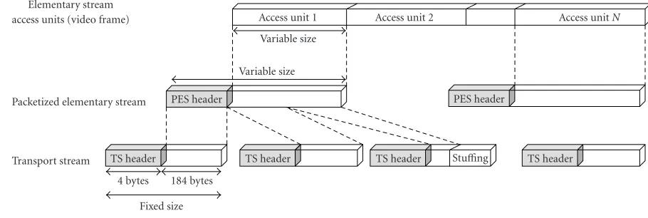
We start by considering the performance evaluation of a DCT-MPEG-2 layer video codec when defining a constant breakpoint for the whole video sequence as previously de-scribed. Under this scheme, a digital MPEG-2 video stream is encoded into two sub-bitstreams. This partitioning is done by taking into account the relevance of the different pieces of information of the MPEG-2 bitstream (fully compatible with the MPEG-2data-partitioning scalable profile specifica-tions [5,6,7]). In layered video communications, the base layer and the enhancement layer need to preserve the struc-ture of the base layer stream. In the case of MPEG-2 stan-dard, this means complete MPEG-2 transport stream (TS) structuring in both layers (seeFigure 3). The MPEG-2 TS is intended for multi-program applications such as broadcast-ing and for non-error-free environments. All the MPEG-2 TS packets are given extra error protection using methods such as Reed-Solomon encoding [5,6,7]. Prioritization of the base layer over the enhancement layer in an MPEG-2 scalable data-partitioning profile using MPEG-2 TS specifi-cations can be done very easily using the transport-priority
field (TS header) and packetized elementary stream (PES)-priorityfield (PES header) [5,6,7].
In order to set the basis towards the definition of a nonlinear layered encoding scheme, we carried an exhaus-tive study by applying the DCT-MPEG-2 layer video codec scheme to seven different video sequences, each one encoded using five differentQ-factor values.
Table 1shows the video sequences characteristics: mean bit rates, frame rates, and the share of bit rate used for all DCT coefficients (DCT-bits) and for the rest of the coded data (Hdr-bits): sequence, picture, and macroblock header data. The picture size of the all video sequences is 720×480 (NTSC CCIR 601). The GOP pattern was set to N = 12,
Fixed size 4 bytes 184 bytes TS header
Transport stream TS header TS header Stuffing TS header
Packetized elementary stream PES header PES header
Variable size Elementary stream
access units (video frame)
Variable size
Access unit 1 Access unit 2 Access unitN
Figure3: MPEG-2 transport stream generation from layered video frames.
Figure 4shows the results obtained for the Ayersroc, Hook, and Table Tennis video sequences. Similar results were ob-tained when applying this scheme to the other four video se-quences.
Figure 4shows that the enhancement layer (LP) can rep-resent a significant portion of the overall bandwidth require-ments. It can also be observed that by varying the breakpoint, we can vary the amount of video data to be included in each layer. For instance, in the case of the Ayersroc, Hook, and Ta-ble Tennis sequences using a breakpoint of five, the enhance-ment layer accounts approximately for 33%, 22%, 15%, 10%, 8% (Ayersroc); 39%, 28%, 17%, 9%, 7% (Hook); and 52%, 42%, 29%, 19%, 11% (Table Tennis) of the total video data when encoded with aQ-factor set to 8, 12, 20, 28, and 40, respectively.
In the following, we will present a quantitative assess-ment of our video quality results using the moving pictures quality metric (MPQM) [31]. MPQM has been proved to behave consistently with human judgments according to the quality scale that is often used for subjective testing in the en-gineering community (seeTable 2) [32,33]. The metric has been developed based on a spatio-temporal model of the hu-man vision system. Therefore, the metric overcomes the lack of correlation of traditional metrics, such as PSNR among others, with human perception. MPQM is based on the ba-sic properties of human vision, mainly, that the human vi-sual system is characterized by a collection of channels that mediate perception. Due to the independent characteristic among the channels, the perception can be predicted channel by channel. In this way, the metric decomposes the original sequence and a distorted version of it into perceptual chan-nels. It then computes a channel-based distortion measure for contrast sensitivity and masking. Throughout our exper-iments, we have confirmed that MPQM effectively assesses the spatio-temporal video quality degradation by rating the video sequence on a frame by frame basis. However, for the sake of clarity, we report the average MPQM for each video-clip encoding instance.
Figure 5depicts the video quality using MPQM for dif-ferent breakpoints applied to the base layer of the Ayersroc,
Hook, and Table Tennis video sequences. As already stated, for the sequences used in our experiments, it was observed that a breakpoint offivecould yield a graceful quality degra-dation (seeFigure 6).
From the results obtained in this evaluation, we can make the following observations.
(1) The amount of overhead introduced by the layered video coding scheme is independent of the selected break-point, that is, independent of the way the DCT coefficients are split between the two layers. It is clear that due to the need of keeping a perfect synchronization between the two layers, the amount of overhead introduced by the scheme is exclusively due to need of including the syntactic video head-ers (sequence, GOP, frame, and slice headhead-ers) in both video layers and the complete MPEG-2 TS structuring in both lay-ers.
(2) The overhead varies with theQ-factor selected. The overhead increases as a function of theQ-factor. By increas-ing theQ-factor, the amount of generated semantic data de-creases while the amount of generated syntactic data (head-ers) remains constant.
(3) The traffic distribution between the two layers reaches a saturation point. The value of this saturation point de-creases as a function of theQ-factor. This is due to the fact that, after the quantization process imbedded in the MPEG-2 video compression algorithm, the number of high-frequency coefficients equal to zero increases as a function of theQ -factor. Since the MPEG-2 video compression algorithm does not encode the DCT coefficients equal to zero, the result-ing compressed image will contain a limited number of DCT coefficients. The saturation point represents the point from which all the DCT coefficients have been included in the base layer, leaving the enhancement layer practically empty (except for the overhead introduced by the layering mecha-nism).
Table1: Video sequence characteristics.
Video sequence
Video sequences characteristics
Mean bit rate (Kbps) Frame rate (fps) Hdr-bits (%) DCT-bits (%)
Ayersroc
Q=8 5460 24 15.08 84.92
Q=12 3421 24 24.64 75.36
Q=20 1950 24 40.19 59.81
Q=28 1455 24 51.60 48.40
Q=40 1136 24 63.42 36.58
Hook
Q=8 6392 24 13.40 86.6
Q=12 3920 24 22.18 77.82
Q=20 2272 24 37.52 62.48
Q=28 1674 24 49.46 50.54
Q=40 1285 24 62.10 37.90
Martin
Q=8 4684 24 15.88 84.12
Q=12 2670 24 27.85 72.15
Q=20 1381 24 49.44 50.56
Q=28 983 24 64.20 35.80
Q=40 785 24 75.30 24.70
Flower Garden
Q=8 14564 30 8.22 91.78
Q=12 9672 30 12.73 87.27
Q=20 5790 30 20.01 79.99
Q=28 4191 30 27.23 72.77
Q=40 3043 30 39.25 60.75
Mobile Calendar
Q=8 17600 30 7.31 92.69
Q=12 11634 30 11.20 88.80
Q=20 6906 30 19.08 80.92
Q=28 4909 30 26.92 73.08
Q=40 3433 30 38.42 61.58
Table Tennis
Q=8 12906 30 11.39 88.61
Q=12 7972 30 19.76 80.24
Q=20 4581 30 35.51 64.49
Q=28 3397 30 45.94 54.06
Q=40 2581 30 56.10 43.90
Football
Q=8 12934 30 12.14 87.86
Q=12 8549 30 18.87 81.13
Q=20 5169 30 31.40 68.60
Q=28 3813 30 42.28 57.72
Q=40 2889 30 54.71 45.29
(5) For a breakpoint of 5, a significant amount of video traffic is assigned to the enhancement layer. For instance, for the sequences Ayersroc, Hook, and Table Tennis, an ac-ceptable quality in the base layer can be obtained while the amount of data traffic pertaining to the enhancement layer is in the order of 40%, 50%, and 53%, respectively. That is to say, this traffic can be discarded if needed due to a lack of resources (spare network bandwidth) without adversely af-fecting the overall video service.
The aforementioned analysis sets up the basis to derive the guidelines towards the definition of an adaptive encoding mechanism.
Q=8
Figure4: Traffic distribution and overhead versus breakpoint. (a) Ayersroc sequence. (b) Hook sequence. (c) Table Tennis sequence.
Table2: Quality scale.
Rating Impairment Quality
5 Imperceptible Excellent
4 Perceptible, not annoying Good
3 Slightly Fair
2 Annoying Poor
1 Very annoying Bad
(ii) The value of the acceptable breakpoint should be de-termined taking into account the desired quality of the image and traffic rate pertaining to the base layer.
(iii) The breakpoint andQ-factor have a direct impact on the assignment of the traffic to the enhancement layer and image quality.
Q=8
Figure5: Quantitative video quality for different breakpoints. (a) Ayersroc sequence. (b) Hook sequence. (c) Table Tennis sequence.
3.1. Encoding principles
According to the quantization process in most video codecs, the 64 DCT coefficients in a block are scanned in the most ef-ficient manner so that the largest possible zero sequence can be obtained; thus a 64-coefficient block is translated into a few pairs (u,v), whereuis the number of DCT coefficients equal to zero before a value v different from zero. These pairs are subsequently coded by means of a codec of variable length, as indicated inFigure 7.
Each pair (u,v) represents a DCT coefficient v dif-ferent from zero in the block and a number of coeffi -cients u equal to zero in the block. These pairs are the data units that the layering scheme will place in the base layer or in the enhancement layer, in terms of a break-point value. The breakbreak-point defines the number of nonzero-valued DCT coefficients in a block to be included in the base layer.
Breakpoint=5 Breakpoint=2 Original image
(a)
Breakpoint=5 Breakpoint=2 Original image
(b)
Breakpoint=5 Breakpoint=2 Original image
(c)
Figure6: Subjective video quality for different breakpoints. (a) Ayersroc sequence (I-picture). (b) Hook sequence (P-picture). (c) Table Tennis sequence (B-picture).
3.2. A frame-aware encoding approach
In order to take into account the relevance of the various types of frames, several proposals studies have suggested the use of a different breakpoint for each type of frame. This can be done by defining breakpoint corrective factors, taking val-ues between 0 and 1, to be used for P- and B-frames. Once a breakpoint has been assigned to I-frames, a reduced break-point is used to encode P-type blocks and an even lower cor-rective factor is assigned for the encoding process of B-type blocks. Even though some studies have shown the benefits of using this scheme in terms of the quality of the video signals reconstructed by exclusively using the base layer, the num-ber of cases evaluated has been rather limited. Furthermore, little attention has been paid to study the effect of varying the breakpoint factor, another major video coding parame-ter affecting the quality of the video signal as well as the data generation rate.
In the following, we carried an exhaustive study by apply-ing a frame-aware nonlinear encodapply-ing scheme to seven dif-ferent video sequences, each one encoded using six different sets of breakpoint values and four differentQ-factor values.
The nonlinear video encoding scheme is evaluated in terms of the quality of the decoded base layer and its corresponding data rate.
3.3. Numerical results
In this section, we will evaluate the frame-aware nonlinear encoding scheme. In the previous section, we have found out that the breakpoint of five provides graceful quantitative and subjective (visual) video qualities degradation for most of the video sequences.Table 3shows the corrective factors used in our studies. As seen from the table, the first set of values cor-responds to the assignment of the same breakpoint value to all frames. For the other five cases, we have applied a correc-tive value to reduce the number of DCT coefficients pertain-ing to the P- and B-frames.
0 0 0 0 0 0 0 0
0 0 0 0 0 0 0 0
1 0 0 0 0 0 0 0
0 0 0 1 0 0 0 0
0 0 0 0 1 0 0 0
3 0 1 2 0 2 0 0
8 6 0 0 0 1 1 0
9 7 4 6 0 0 0 0
Entropy coding
(0, 9)(0, 7)(0, 8)(0, 3)(0, 6)(0, 4)(0, 6)(5, 1)(4, 2)(2, 1)· · ·
Representation (u,v) or RLC
9, 7, 8, 3, 6, 4, 6, 0, 0, 0, 0, 0, 1, 0, 0, 0, 0, 2, 0, 0, 1,. . . Zigzag scan order
64 DCT coefficients
Figure7: A 64-DCT block representation in pairs (u,v).
Table3: Corrective factors.
Option I P B
Uniform (static) 1 1 1
O1 1 0.75 0.75
O2 1 0.75 0.5
O3 1 0.75 0.25
O4 1 0.5 0.5
O5 1 0.5 0.25
From the figures, it is clear that for each breakpoint value, a uniform breakpoint assignment results in the best video quality. However, this set-up corresponds to the low-est percentage of traffic assigned to the enhancement layer (highest percentage of traffic assigned to the base layer). From the results, it is clear that the quality of the video re-constructed using exclusively the base layer deteriorates as the size of the enhancement layer increases (more data is removed from the base layer). It is clear from the figure that in order to improve the overall system performance in terms of the quality and traffic volume, it is necessary not only to apply a corrective factor but as well to change the breakpoint value. From Figures 8–10, we observe that when the breakpoint value is set to 8 and by using a cor-rective factor option, such as O3 or O5, we are able to move an important amount of data to the enhancement layer and obtain a better or comparable video quality to the one achieved using a uniform breakpoint assignment and a breakpoint= 5.
A closer look at Figures8–10also shows that by making the aforementioned changes to the encoding parameters, the system performance has been improved by the fact of includ-ing more I-frame DCT coefficients into the base layer. More specifically, the nonlinear scheme provides a better overall as-signment of the DCT coefficients in a block to the base layer
when compared to the linear encoding scheme. The figures clearly show the trend of the proposed scheme. By taking into account the relevance of the different frame types, the nonlinear scheme is able to include a larger number of DCT coefficients pertaining to the I-frames while reducing accord-ingly the number of DCT coefficients belonging to the P- and B-frames. It is also worth to mention that this trend is ac-centuated as the breakpoint is increased from 5 to 8. This translates into a better or similar image quality of the base layer as well as an important decrease in the base layer traf-fic, that is, a reduction in the amount of the data required to achieve an acceptable video quality. The best results are obtained when applying options O3 and O5, O5 being the most restrictive of the policies under study; only half and a quarter of the DCT coefficients belonging to the P- and B-frame types are included in the base layer, respectively. These results clearly show the effectiveness of the proposed scheme.
In order to further explore the performance of this en-coding scheme, we have evaluated seven different video se-quences, encoded using four different values for theQ-factor as well as the six corrective breakpoint assignments.Table 4 lists the results obtained when using the uniform assignment case and option O5.
A closer look at the results inTable 4allows us to make the following observations.
(i) In all cases, there is a significant increase in the amount of data being moved to the enhancement layer. The change is far more important for low values of theQ -factor.
(ii) For all but one sequence, the quality of the base layer is improved when using option O5 and breakpoint =8 as compared to the case breakpoint=5 and a uniform breakpoint value.
(# DCT) I-frames (# DCT) P-frames (# DCT) B-frames
Video quality in the base layer enhancement layer traffic (%) S O1 O2 O3 O4 O5 S O1 O2 O3 O4 O5 S O1 O2 O3 O4 O5 S O1 O2 O3 O4 O5
Breakpoint=5 Breakpoint=6 Breakpoint=7 Breakpoint=8 0
Video quality in the base layer enhancement layer traffic (%) S O1 O2 O3 O4 O5 S O1 O2 O3 O4 O5 S O1 O2 O3 O4 O5 S O1 O2 O3 O4 O5
Breakpoint=5 Breakpoint=6 Breakpoint=7 Breakpoint=8 0
Figure8: Performance of the frame-aware layering scheme for the Hook video sequence: (a)Q=8 and (b)Q=12.
options 1 to 5 clearly shows the benefits of tak-ing into account the relevance of the different pieces of information. As we increase the breakpoint value
(# DCT) I-frames (# DCT) P-frames (# DCT) B-frames
Video quality in the base layer enhancement layer traffic (%) S O1 O2 O3 O4 O5 S O1 O2 O3 O4 O5 S O1 O2 O3 O4 O5 S O1 O2 O3 O4 O5
Breakpoint=5 Breakpoint=6 Breakpoint=7 Breakpoint=8 0
Video quality in the base layer enhancement layer traffic (%) S O1 O2 O3 O4 O5 S O1 O2 O3 O4 O5 S O1 O2 O3 O4 O5 S O1 O2 O3 O4 O5
Breakpoint=5 Breakpoint=6 Breakpoint=7 Breakpoint=8 0
Figure9: Performance of the frame-aware layering scheme for the Ayersroc video sequence: (a)Q=8 and (b)Q=12.
a GOP will be decoded using as reference the I-frame, the increase of the quality in the I-frames paysoff. The inclusion of more DCT coefficients belonging
(# DCT) I-frames (# DCT) P-frames (# DCT) B-frames
Video quality in the base layer enhancement layer traffic (%) S O1 O2 O3 O4 O5 S O1 O2 O3 O4 O5 S O1 O2 O3 O4 O5 S O1 O2 O3 O4 O5
Breakpoint=5 Breakpoint=6 Breakpoint=7 Breakpoint=8 0
Video quality in the base layer enhancement layer traffic (%) S O1 O2 O3 O4 O5 S O1 O2 O3 O4 O5 S O1 O2 O3 O4 O5 S O1 O2 O3 O4 O5
Breakpoint=5 Breakpoint=6 Breakpoint=7 Breakpoint=8 0
Figure10: Performance of the frame-aware layering scheme for the Table Tennis video sequence: (a)Q=8 and (b)Q=12.
From the results, it is clear that theDCT-based nonlin-ear layered video codec shows a good compromise between the amount of relevant traffic and the quality of the image.
Table4: Performance results.
Video sequence
Uniform option (breakpoint=5) Frame-aware option O5 (breakpoint=8)
DCT No. of
coefficients for I, P, B LP traffic (%) HP quality coefficients for I, P, BDCT No. of LP traffic (%) HP quality
Ayersroc
Q=8 31.70, 40.94, 50.84 30.90 3.95 42.37, 35.93, 32.30 46.41 3.98 Q=12 38.23, 49.09, 56.15 20.98 4.01 49.72, 44.69, 41.94 31.90 4.02 Q=20 47.71, 55.40, 58.78 12.85 3.97 58.29, 51.57, 47.29 18.76 3.95 Q=40 59.29, 61.41, 62.52 5.89 3.46 63.52, 59.07, 52.14 7.95 3.44
Hook
Q=8 36.65, 39.81, 44.47 37.14 4.23 47.22, 35.36, 28.52 52.18 3.91 Q=12 44.14, 46.02, 50.37 25.28 4.26 50.03, 42.07, 35.44 39.27 3.95 Q=20 53.09, 52.47, 56.03 13.94 4.17 60.67, 48.40, 40.41 24.23 3.91 Q=40 61.75, 61.48, 62.70 4.72 3.53 63.88, 58.85, 50.96 8.64 3.44
Martin
Q=8 35.83, 48.29, 54.00 24.90 4.51 46.35, 43.26, 34.92 41.19 4.60 Q=12 44.88, 56.51, 59.65 14.97 4.47 54.90, 53.49, 47.36 23.91 4.54 Q=20 56.40, 60.55, 62.04 8.69 4.27 61.89, 58.65, 54.62 11.94 4.30 Q=40 62.91, 63.30, 63.53 5.51 3.69 63.87, 62.67, 60.00 6.22 3.69
Flower Garden
Q=8 23.36, 25.67, 34.49 58.42 2.20 29.42, 22.61, 22.04 68.93 2.50 Q=12 27.35, 31.15, 43.59 46.27 2.30 34.25, 27.67, 28.47 57.78 2.60 Q=20 34.01, 40.26, 54.56 30.25 2.47 41.05, 36.06, 39.39 39.74 2.80 Q=40 44.73, 55.13, 62.16 12.95 2.64 52.49, 51.49, 53.48 15.39 3.01
Mobile Calendar
Q=8 20.29, 30.96, 39.35 62.22 1.95 27.80, 27.66, 27.48 71.81 2.68 Q=12 24.92, 36.96, 44.89 51.97 2.05 33.23, 33.49, 32.86 62.28 2.75 Q=20 32.19, 45.00, 51.68 36.41 2.19 41.61, 41.41, 39.50 46.48 2.84 Q=40 44.65, 55.57, 58.92 16.83 2.32 52.50, 52.58, 49.57 21.46 2.82
Table Tennis
Q=8 32.07, 38.75, 46.49 52.06 3.10 40.85, 35.34, 33.83 63.04 3.45 Q=12 40.46, 44.56, 51.60 42.65 3.18 48.52, 41.75, 41.28 51.93 3.54 Q=20 49.28, 48.85, 55.99 28.95 3.27 54.46, 45.89, 45.75 37.64 3.61 Q=40 57.09, 58.51, 61.44 10.72 3.12 60.25, 56.34, 54.12 14.28 3.37
Football
Q=8 25.19, 30.52, 38.61 49.19 2.31 34.16, 26.46, 23.93 58.74 2.32 Q=12 31.91, 38.14, 43.47 39.15 2.40 44.04, 34.20, 29.91 48.93 2.43 Q=20 45.51, 45.58, 48.51 25.70 2.57 55.75, 41.71, 33.73 34.48 2.70 Q=40 58.23, 54.76, 57.89 9.66 2.73 62.08, 51.3, 42.77 15.05 2.78
simply stated as follows:
(i) for a target video quality, setQto a given (constant) value;
(ii) determine a breakpoint ensuring a minimum accept-able video quality;
(iii) using as a basis the breakpoint in the previous point, apply a corrective factor to the breakpoint to be used to encode the P- and B-frames;
(iv) the factor to apply to the P-frames should be larger than the factor to be used for the B-frames.
A video encoder incorporating these features could adapt its encoding parameters in response to a congestion signal from the network in order to reduce the amount of data while maintaining the best possible acceptable video qual-ity. For instance, assume that under normal operation, the
encoder operates with a breakpoint=5 and a uniform cor-rective factor; in response to a congestion condition, the en-coder could change both the breakpoint and the corrective factors. If a more severe congestion condition is encountered, the encoder could decide to change only the corrective factors that for all cases results in a significant video-generation rate drop. This latter mode of operation proves to be very use-ful due to the fact that under severe network conditions, the encoder can quickly react by simply changing the corrective factors without having to change theQ-factor.
4. CONCLUSIONS
sequence. We have analyzed the scheme by applying it to seven different video sequences and by changing the encoder parameters. From our results, we have found that, for most of the cases analyzed, it is feasible to gracefully degrade or even ensure a minimum acceptable video quality while reducing the amount of data used to represent the video sequence. We have therefore derived the major guidelines to set up the en-coding parameters. We have also outlined an adaptive encod-ing process to be used in conjunction with a rate-based con-gestion control mechanism.
ACKNOWLEDGMENTS
This work was supported by the Ministry of Science and Technology of Spain under CICYT Project TIC2003-08154-C06-02, the Council of Science and Technology of Castilla-La Mancha under Project PBC-03-001, and the Natural Sciences and Engineering Council of Canada.
REFERENCES
[1] P. Cuenca, L. Orozco-Barbosa, F. Quiles, and A. Garrido, “Loss-resilient ATM protocol architecture for MPEG-2 video communications,”IEEE Journal on Selected Areas in
Commu-nications, vol. 18, no. 6, pp. 1075–1086, 2000.
[2] P. Cuenca, A. Garrido, F. Quiles, and L. Orozco-Barbosa, “Some proposals to improve error resilience in the MPEG-2 video transmission over ATM networks,” inProc. 17th An-nual Joint Conference of the IEEE Computer and
Communica-tions Societies, vol. 2, pp. 668–675, San Francisco, Calif, USA,
March-April 1998.
[3] P. Cuenca, A. Garrido, F. Quiles, and L. Orozco-Barbosa, “An efficient protocol architecture for error-resilient MPEG-2 video communications over ATM networks,” IEEE
Transac-tions on Broadcasting, vol. 45, no. 1, pp. 129–140, 1999.
[4] ISO/IEC 14496, Information technology-Generic coding of audio-visual objects- Part 2: Visual. Final Committee Draft of International Standard, Seoul, March 1999. Part 1: System; Part 2: Visual; Part 3: Audio, Part 4: Conformance Testing; Part 5: Technical Report; Part 6: Delivery Multimedia Integra-tion Framework.
[5] ISO/IEC 13818-1, “Information technology—generic cod-ing of movcod-ing pictures and associated audio information— Part 1: Systems,” International Standard, ISO/IEC/JTC1/SC29 WG11, 2000.
[6] ISO/IEC 13818-2, “Information technology—generic coding of moving pictures and associated audio information—Part 2: Video,” International Standard, ISO/IEC/JTC1/SC29 WG11, 2000.
[7] ISO/IEC 13818-3, “Information technology—generic coding of moving pictures and associated audio information—Part 3: Audio,” International Standard, ISO/IEC/JTC1/SC29 WG11, 1998.
[8] ISO/IEC 11172-1, “Information technology—coding of mov-ing pictures and associated audio for digital storage media at up to about 1,5 mbits—Part 1: Systems,” International Stan-dard, ISO/IEC/JTC1/SC29 WG11, 1993.
[9] ISO/IEC 11172-2, “Information technology—coding of mov-ing pictures and associated audio for digital storage media at up to about 1,5 mbits—Part 2: Video,” International Stan-dard, ISO/IEC/JTC1/SC29 WG11, 1993.
[10] ISO/IEC 11172-3, “Information technology—coding of mov-ing pictures and associated audio for digital storage media at up to about 1,5 mbits—Part 3: Audio,” International Stan-dard, ISO/IEC/JTC1/SC29 WG11, 1993.
[11] ISO/IEC 11172-4, “Information technology—coding of mov-ing pictures and associated audio for digital storage media at up to about 1,5 mbits—Part 4: Compliance testing,” Interna-tional Standard, ISO/IEC/JTC1/SC29 WG11, 1995.
[12] ISO/IEC 14496-1, “Information technology—coding of audio-visual objects—Part 1: Systems,” International Stan-dard, ISO/IEC/JTC1/SC29 WG11, 2001.
[13] ISO/IEC 14496-2, “Information technology—coding of audio-visual objects—Part 2: Visual,” International Standard, ISO/IEC/JTC1/SC29 WG11, 2004.
[14] ISO/IEC 14496-3, “Information technology—coding of au-dio-visual objects—Part 3: Audio,” International Standard, ISO/IEC/JTC1/SC29 WG11, 2001.
[15] ISO/IEC 14496-4, “Information technology—coding of au-dio-visual objects—Part 4: Conformance testing,” Interna-tional Standard, ISO/IEC/JTC1/SC29 WG11, 2000.
[16] ISO/IEC 14496-5, “Information technology—coding of audio-visual objects—Part 5: Reference software,” Interna-tional Standard, ISO/IEC/JTC1/SC29 WG11, 2001.
[17] ISO/IEC 14496-6, “Information technology—coding of audio-visual objects—Part 6: Delivery multimedia integration framework (dmif),” International Standard, ISO/IEC/JTC1/SC29 WG11, 2000.
[18] S. Worrall, S. Fabri, A. H. Sadka, and A. M. Kondoz, “Priori-tisation of data partitioned MPEG-4 video over mobile net-works,” ETT-European Transactions on Telecommunications, vol. 12, no. 3, pp. 169–174, 2001.
[19] M. Ghanbari, “Two-layer coding of video signals for VBR net-works,” IEEE Journal on Selected Areas in Communications, vol. 7, no. 5, pp. 771–781, 1989.
[20] P. Pancha and M. El Zarki, “MPEG coding for variable bit rate video transmission,”IEEE Communications Magazine, vol. 32, no. 5, pp. 54–66, 1994.
[21] M. R. Ismail, I. E. Lambadaris, M. Devetsikiotis, and A. R. Kaye, “Modelling prioritized MPEG video using TES and a frame spreading strategy for transmission in ATM networks,”
inProc. 14th Annual Joint Conference of the IEEE Computer
and Communications Societies, vol. 2, pp. 762–770, Boston,
Mass, USA, April 1995.
[22] M. R. Karim,ATM Technology and Services Delivery, Prentice Hall, Upper Saddle River, NJ, USA, 2000.
[23] ETSI,Broadband Radio Access Networks (BRAN) HIPERLAN type 2—Data link control (DLC)—Part 1: Basic data transport
functions, TS 101 761-1, December 2001.
[24] IEEE 802.11a/D5.0, Wireless LAN medium access control (MAC) and physical layer (PHY) specifications: higher speed
physical layer (PHY) extension in the 5 GHz band, April 1999.
[25] IEEE 802.11b/D5.0, Wireless LAN medium access control (MAC) and physical layer (PHY) specifications: higher speed
physical layer (PHY) extension in the 2.4 GHz band, April 1999.
[26] M. Toukourou and L. Orozco-Barbosa, “On the performance of MPEG-2 video-on-demand over RSVP,” inProc. SPIE
Net-work Control and Service Quality Conference, vol. 4211 of
Pro-ceedings of SPIE, pp. 13–24, Boston, Mass, USA, November
2000.
[27] E. Rosen, A. Viswanathan, and R. Callon, “Multiprotocol label switching architecture,” RFC 3031, January 2001.
[28] H. Yu, D. Makrakis, and L. Orozco-Barbosa, “Experimen-tal evaluation of MPEG-2 video over differentiated services IP networks,” inProc. IEEE Pacific Rim Conference on
Communi-cations, Computers and Signal Processing, vol. 2, pp. 469–472,
Victoria, BC, Canada, August 2001.
[29] K. N. Ngan, C. W. Yap, and K. T. Tan,Video Coding for Wireless
Communication Systems, Signal Processing and
[30] L. Hanzo, P. J. Cherriman, and J. Streit, Wireless Video
Com-munications: Second to Third Generation Systems and Beyond,
Mobile & Wireless Communications. Wiley-IEEE Computer Society, New York, NY, USA, 2001.
[31] C. J. Van den Branden and O. Verscheure, “Perceptual quality measure using a spatio-temporal model of the human visual system,” inProc. SPIE Digital Video Compression: Algorithms
and Technologies, vol. 2668 ofProceedings of SPIE, pp. 450–
461, San Jose, Calif, USA, January 1996.
[32] P. Frossard and O. Verscheure, “AMISP: a complete content-based MPEG-2 error-resilient scheme,” IEEE Trans. Circuits
and Systems for Video Technology, vol. 11, no. 9, pp. 989–998,
2001.
[33] O. Verscheure, P. Frossard, and M. Hamdi, “User-oriented QoS analysis in MPEG-2 video delivery,”Journal of Real-Time
Imaging, vol. 5, no. 5, pp. 305–314, 1999.
Pedro Cuenca received his M.S. degree in physics (electronics and computer sci-ence, extraordinary award) from the Uni-versity of Val`encia in 1994. He got his Ph.D. degree in computer engineering in 1999 from the Polytechnic University of Valen-cia, Spain. In 1995, he joined the Depart-ment of Computer Engineering, the Univer-sity of Castilla-La Mancha. He is currently an Associate Professor of communications
and computer networks. He has also been a Visiting Researcher at the Nottingham Trent University, Nottingham, England, and at the Multimedia Communications Research Laboratory, University of Ottawa, Canada. His research topics are centered in the area of high-performance networks, wireless LAN, video compression, QoS video transmission, and error-resilient protocol architectures. He has served in the organization of international conferences as a Session Chair. He has been a reviewer for several journals and for several international conferences. He is a member of the IFIP 6.8 Working Group and a member of the IEEE.
Luis Orozco-Barbosa received his B.S. degree in electrical and computer en-gineering from Universidad Aut ´onoma Metropolitana, Mexico, in 1979, the Diplome d’´etudes Approfondies from ´Ecole Nationale Sup´erieure d’Informatique et de Math´ematiques Appliqu´ees (ENSIMAG), France, in 1984, and the Doctorat de l’Universit´e from Universit´e Pierre et Marie Curie, France, in 1987, both in computer
science. From 1991 to 2002, he was a faculty member in the School of Information Technology and Engineering (SITE), University of Ottawa, Canada. In 2002, he joined the Department of Computer Engineering at the University of Castilla-La Mancha, Spain. He has also been appointed a Director of the Albacete Research Institute of Informatics, a National Centre of Excellence. He has conducted numerous research projects with the private sector and served as a Technical Advisor for the Canadian International Development Agency (CIDA). He has published over 180 papers in international journals and conferences on computer networks and performance evaluation. His current research interests include Internet protocols, network planning, wireless communications, traffic modeling, and performance evaluation. He is a member of the IEEE.
Francisco Delicadoreceived his M.S. de-gree in physics (electronics and computer science) from the University Complutense of Madrid, Madrid, Spain, in 1995. He is currently a Ph.D. degree student in the De-partment of Computer Engineering at the University of Castilla-La Mancha. His re-search interests include high-performance networks, wireless networks, video com-pression, video transmission, and error-resilient protocol architectures.
Antonio Garrido received the degree in physics (electronics and computer science) and the Ph.D. degrees from the Univer-sity of Granada, Spain, in 1986 and Uni-versity of Valencia, Spain, in 1991, respec-tively. In 1986, he joined the Department of Computer Engineering at the Univer-sity of Castilla-La Mancha, where he is cur-rently a Full Professor of Computer Archi-tecture and Technology and Dean of the