32
Implementation of On-Board Weighing System
for Trailer Application
Vijay Patel P 1
P
, Vinay Khatod P 2
P
1
P
Mechanical Engineering, Ganpat University, Kherva, Gujarat, India
P
2
P
Automobile Engineering, Ganpat University, Kherva, Gujarat, India
Abstract
Now days, fast growth of the manufacturing industry is possible by rapid development and advancement in material handling equipment for their accurate and productive operations. There are different industrial sectors like timber, waste, aggregate, general trucking, mining; construction etc. uses the trailer for material handling. Some of the common problems are faced by such above applications like under loading, over loading, loading time loss, traffic fines, pay load over legal limits etc. The above problem can be eliminated by designing and implementing of on board weighing system.
Keywords: Trailer, On-Board Monitoring, On-Board Weighing System, Weight Monitoring System
1. Introduction
The trailer application generally used for the material handling operation in different industrial sector, but the ordinary trailer application poses basic problem about unknown weight so, there is a scope of design and implementation of trailer application by on board weighing system. The on board weighing system poses some basic features like low running cost, reducing loading time, adapted to any type of trailer or trolley. On-board weighing solutions can be implemented for all types of trucks and trailers. On-Board Scales help maximize your load while reducing costs keeping you in the profit zone, while avoiding over loading fines.
An onboard weight monitoring system displayed the true load weights on your onboard system at all times. In this on board weighing system weight is carried out by load cell mounted below the trailer platform and display actual weight on display board. Weighing system mainly consist of strain gauge which give the actual weight.
2. Experiment of Trailer
The on-board weighing system experiment perform on the small trailer used with 15 hp tractor for material handling with maximum loading capacity 1 ton. The existing small trailer design is very simple, and there is no arrangement for doing weight on trailer platform. The specifications of 15 hp mini tractor (figure 1) are given as below.
2.1 Tractor Specification
2.1.1 Weight of Tractor
With Oil & Diesel 845 Kg
Without Standard Ballast
2.1.2 Dimensions
Length - 2286 Mm
Width - 1016 Mm/1168 Mm
Height - 1955 Mm with Exhaust Pipe
Ground Clearance - 260 Mm
Track Width - 812 Mm/965 Mm (Driving Wheels)
33 2.1.3 Transmission
Minimum Turning Radius - 2.6 Meters (With Brakes), 2.8 Meters (Without Brakes)
2.2 Existing Trailer Specification
Length: 5ft
Width: 2.5ft
Height: 1ft
Axel: Single
Chassis: Three, Size 3 x 1.5 inch
Wheel: Two
Pay Load: 1 tone
Hydraulic pump: 1 tone capacity
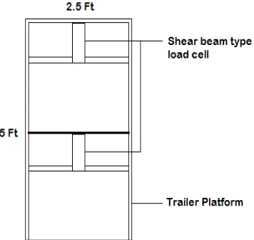
2.3 Implementation of Trailer Design
Now this Existing trailer is implemented by designing a Shear beam type two Load Cell, with changes in trailer design. Implemented Trailer design and two load cell exact position shown in figure.2. In this design making one more platform, which is fitted on two load cell mounted on the trailer fixed platform.
2.4 Load Cell Design
Load cell description, feature, electrical connection, technical specification, and construction diagram are described below.
2.4.1 Description
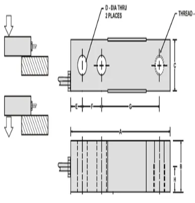
This is a strain gage based, single ended shear beam load cell designed for multiple uses in low profile platform scales & in tank, trailer, bin and hopper weighing systems. It is constructed from high alloy tool Steel for excellent resistance to shock and overload. The cell is sealed against moisture ingression for use in wash-down areas and it is electro less nickel plated for corrosion resistance [3]. It is low cost ideal load cell for industrial automation applications. Figure 3 shows the electrical connection and figure 4 shows the load cell diagram.
2.4.2 Feature
100 Kg to 10000 Kg capacities offered.
Complete environmental protection.
Protection available optionally with laser welded sealing.
Standardized output (3.0 ± 0.25%) available on request.
Fig. 2 Trailer Design
34 2.4.3 Electrical Connection
Fig. 3 Electrical Connection
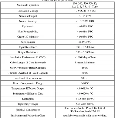
2.4.4 Technical Specification
Table 1 Technical Specification
Standard Capacities 100, 200, 300,500 Kg
1, 2, 3, 5, 7.5, 10 Tone.
Excitation Voltage 10 VDC to15 VDC
Nominal Output 3.0 m V/ V
Non – Linearity < ±0.025% FSO
Hysteresis < ±0.02% FSO
Non-Repeatability < ±0.01% FSO
Creep (30 minutes) < ±0.03% FSO
Zero Balance ±1.0% FSO
Input Resistance 390 ± 3.5 Ohms
Output Resistance 350 ± 3.5 Ohms
Insulation Resistance (50 VDC) > 1000 Mega Ohms
Cable Length (4 Core Screened) 5 meter. Minimum
Safe Overload of Rated Capacity 150%
Ultimate Overload of Rated Capacity 300%
Side Load Discrimination 500 : 1
Temp. Compensated Range 0-60 P
0
P
C
Temperature Effect on Output < 0.0015% P
0
P
C
Temperature Effect on Zero < 0.0020% P
0
P
C
Deflection < 0.5 mm at FSO
Tightening Torque See table below.
Finish & Construction Electro less Nickel Plated Tool Steel
SS-Stainless Steel-17-4 PH
35 2.4.5 Construction Drawing
3. Working of Strain Gauge
Strain is the amount of deformation of a body due to an applied force. More specifically, strain (e) is defined as the fractional change in length. A strain gauge is a device whose electrical resistance varies in proportion to the amount of strain in the device which is shown in figure 5. The most widely used gauge is the bonded metallic strain gauge [2].
A length change of a wire causes a resistance change, which is measured by a strain gauge [4].
𝑅
=
𝜌𝐿
𝐴
Where, R = Resistance
𝜌 = Resistivity (Materialistic Property) L = Length of Wire
A = Area of Wire
Change of Resistance,
𝑑𝑅= 𝛿𝑅𝛿𝜌 𝑑𝜌+ 𝛿𝑅
𝛿𝐿 𝑑𝐿+ 𝛿𝑅
𝛿𝐴𝑑𝐴
𝑉= 𝐿𝑜𝑛𝑔𝑖𝑡𝑢𝑑𝑖𝑛𝑎𝑙𝑇𝑟𝑎𝑛𝑠𝑣𝑒𝑟𝑠𝑒𝑆𝑡𝑎𝑟𝑖𝑛𝑆𝑡𝑟𝑎𝑖𝑛= −𝜀𝑡𝜀𝑙=
−1 2 ∗ 𝑑𝐴𝐴
𝑑𝐿 𝐿 �
Gauge Factor,
𝐺.𝐹. = ∆𝑅∆𝐿�𝑅
𝐿 � =
∆𝑅 𝑅 � 𝜀
The G.F. relates a change in resistance with strain, for most elements, G.F. ranges from 2.0-4.0 e.g., constantan = 2.0, Nichrome = 2.2 [2].
Fig. 5 Working of Strain Gauge
36
4. Measurement of Load on Trailer
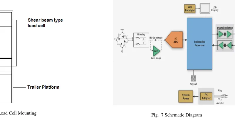
Imagine your truck without a speedometer. It would be complicated and stressful especially at control points. Well, it’s the same for your load, if you have no device monitoring your load weight; you are working blindly. An onboard weight monitoring system eliminates that problem. Now, the true load weights are displayed on your onboard system at all times. In this on board weighing system weight is carried out by Load Cell mounted below the trailer platform and display actual weight on display board, which is shown in figure 6 [1]. Weighing system mainly consist of strain gauge which give the actual weight [4].
Now, when weight place on the trailer platform at that time metallic foil gauges are stretched, and resistance of the circuit are also change. Gain is produced in the form of analog signal. That signals filter or conditioning by the instrumentation amplifier, and converted by the ADC in to digital signals, and sends it to the embedded processor, than display on the LED display or LCD display [5]. Here system power supply to strain gauges, embedded processor, and display board from the trailer battery source or 12v Battery fitted with control box, which are shown in schematic diagram in figure 7.
5. Result of On-Board Weight
By this method, weighing is done on the trailer platform with more accuracy, and any time you know the current weight put on the trailer as shown in figure 8. Result of weight is done by putting different weights at five different positions on trailer platform, and its result shown in table 2.
Fig. 8 On-Board Trailer Application
37 Table 2 Result of On-Board Weight
No more uses of the weighbridge to monitor the weight load, No more premature wear damage caused by overloads, No more stress. The on board weighing system poses some basic features like low running cost, reducing loading time, adapted to any type of truck trailer or trolley.
6. Conclusion
On board weighing enables you to carry maximum payload within legal limits, eliminates overloading and traffic fines, reduced loading times, compatible and interchangeable with most tipping vehicles, low running costs, adapted to any types of trucks. In future work, the whole system uncertainty will be verified under known or controlled conditions to determine the accuracy of the measuring system. Moreover, strong wind will shake trailers, which leads to flickering of displayed data, making data reading difficult. Therefore weather condition and temperature must be considered.
References
[1] S. K. Yang, T. S. Liu, Y .C. Cheng "Automatic measurement of payload for heavy vehicles using strain gauges". Measurement 41 (2008) 491–502.
[2] R. R. Desai, D. Lakhminarayana, P. B. Patel, C. J. Panchal "Thin film strain gauge". Sardar Patel University, Vallabh Vidyanagar- 388120, Gujarat, India. Sensors and Actuators A 121 (2005) 405- 409.
[3] A. Karaus and H. Paul, Hottinger Baldwin Messtechnik GmbH, Darmstadt, Germany. "Load cells with small nominal load based on strain gauges using thin-film techniques. Measurement" Volume 10, Issue 3, July-September 1992, Pages 133-139
[4] Colm Slattery, Mariah Nie, “A Reference Design for High Performance, Low-Cost Weigh Scales”. Analog Dialogue 39-12, December (2005).
[5] Jorge Figueroa, William St. Cyr, and Shamim Rahmart, Gregory McVay, David Van Dyke, William Mitchell, and Lester Langford, "Strain-Gauge Measurement of Weight of Fluid in a Tank", Stennis Space Center, (228) 688-1929. Refer to SSC-00187.
Vijay Patel, VICE PRINCIPAL at B. S. Patel Polytechnic, Ganpat University complete his Post-Graduation in Advance Manufacturing and Technology
from Ganpat University. He pursued his Bachelor of Engineering in Mechatronics Engineering from Hemchandracharya North Gujarat University, Patan. During his teaching period he guided number of Mechatronics students with their projects, and also arranged number of automation workshop at college like Robotics, Arduno Robotics, IOT And Vehicle Overhauling. He has also published number of paper in International Journal and presented papers in various Conferences.
Vinay Khatod, Assistant Professor at Ganpat University achieved Bronze Medal in Master of Engineering program from Gujarat Technological
University in Mechanical Engineering (I. C. Auto.). He pursued his Bachelor of Engineering in Automobile Engineering from Indus University, Ahmedabad. During his Academics he has designed and fabricated an Engine running on Alternative Fuel to Preserve Environment from Harmful Pollutants. Also, he re-modeled F-Head Engine to increase its efficiency. He has guided number of Projects at Diploma and Bachelor’s Level. He has published couple of scholarly articles in National and International Journals and Conferences. He has attended number of Seminars, Conferences and Workshops for continual Development and understanding future engineering inventions.
NO. WEIGHT POSITION RESULTS
1 200 Kg
Upper left Upper right Lower left Lower right Centre point ±199.97 Kg ±199.97 Kg ±200.00 Kg ±200.00 Kg ±200.00 Kg
2 400 Kg
Upper left Upper right Lower left Lower right Centre point ±399.98 Kg ±399.98 Kg ±400.00 Kg ±400.00 Kg ±400.00 Kg
3 600 Kg