Closed Loop Control of Multipulse Rectifier
Using Novel Modulation Techniques
S.Kirthika1
Assistant Professor, Dept. of EEE, M.Kumarasamy College of Engineering, Karur, India1
ABSTRACT: This paper deals with strategy of closed loop control for 12 pulse rectifier with hybrid technology having two boost stage switches for regulation o output voltage. The output voltage is directly controlled by space vector modulation with the help of closed loop technology and input current is sinusoidal. The result shows the control strategy gives input current with high quality for all and also distorted, unbalanced main.
KEYWORDS: 12-pulse rectifier, closed-loop control,space-vector modulation.
I. INTRODUCTION
The More-electric aircraft (MEA) rectifier Systems are used to reduce the distortions in main voltage and disturbances in sensitive flight control equipment . This can be achieved only by using high input current quality of MEA system. To get regulated input current, number of pulses is increased using PWM technique. The losses in the Electromagnetic interference filter, the low efficiency and cooling effect, without any galvanic isolation of 12 pulse diode rectifier is because of high frequency range between 360 to 800 Hz. This can be achieved by using phase shift auto transformer which is denoted as main side line interface transformer that can be operated using medium switching frequency. With low complexity and higher pulse load capability is determined by using passive system. The Electromagnetic interference filter is not required in multi pulse rectifier. The elimination of low frequency harmonica is done by mutual cancellation and high frequency switching is not needed. However, the strength of the signal is reduced by low pass electromagnetic interference filter without any switching frequency harmonics. The displacement of main voltage and input current is determined by avoiding capacitive phase. A low power factor is fixed at particular load or it may be of 800 Hz high main frequency. Phase displacement is due to capacitors present in electromagnetic interference filter , which cannot be equaled by single directional pulse width modulation rectifier system.
To increase the pulse number from 12 pulse to 24 pulse, interphase reactors and diodes are used on DC side, while providing the AC side. Low power is produced by inductive components which can be obtained by 12 pulse rectifier. The transformer and four diode bridges are used to obtain 24 pulse system. Control circuit is eliminated by omitting active switches. i.e the characteristics of above system includes low complexity and high robustness. For voltage adaption, the characteristic of delta – delta and delta – star isolation transformer are used in 12 pulse topology. So that the voltage of 115V is converter to 28 V DC bus by generating two-phase-shifted three-phase diode rectifier input-voltage systems. In higher voltage system, the rater power of inductive components from 1.0 to ≈0.2 PO is reduced by replacing isolation transformer to phase shift auto transformer which results in less volume and lower weight topology.
ISSN (Print) : 2320 – 3765 ISSN (Online): 2278 – 8875
I
nternational
J
ournal of
A
dvanced
R
esearch in
E
lectrical,
E
lectronics and
I
nstrumentation
E
ngineering
(An ISO 3297: 2007 Certified Organization)
Website: www.ijareeie.com
Vol. 6, Issue 2, February 2017
Fig 1. Classification of 12-pulse diode-rectifier systems.
II.OPEN LOOP CONTROL
The output of voltage and current in diode bridges have to be differentiated in hybrid autotransformer rectifier units. Therefore, the main side current is fascinated by inductors which are connected in series or autotransformer input is provided by main voltage . On dc side, only the switches which are active is employed that allows passive smoothing replacement and slenderizing components of inductive elements by high frequency current or voltage. It affects dc-dc converters which allow dc output voltage control to some constant value. Moreover, to have sinusoidal main current, the output voltage or current of rectifier have to be regulated. Therefore, the difficulty of the control is restricted and hence the implementation of DC-DC converter is done.
The proposed system includes current output produced by Diode Bridge in hybrid autotransformer rectifier unit. The necessity of interphase reactors for autotransformer rectifier unit is to support the distinguish of output voltage of diode bridge and to slenderize dc currents which are replaced by DC-DC boost converter that are parallely connected at output side. This helps in system reduction and also control in output voltage. The output currents of bridge rectifier is minimized to some constant value but higher pulses are not required. For triangular DC current. The dc current of triangular modulation is obtained by 12 Pulse system topology, that had shown increment of pulse number. With the help of electronic interphase reactor and electronic inductor, the achievement of triangular wave shaping current is done. In this the observer can obtain its output power. By using passive rectifier bridge, the higher efficiency of overall system and power conversion performance have been determined.
The 12 pulse rectifier topology is determined by the concept of conventional isolated transformer and not analysed by hybrid Automatic Transformer Rectifier Units.
Fig 2. Impressed/modulated diode-bridge output current and impressed ac-side voltage
The continuous conduction mode (CCM) can be obtained by controlling output voltage in 12 pulse conventional system. Compared to 12 pulse automatic transformer rectifier unit there is no improvement in main behavior. Moreover the sinusoidal shaping is not achieved in main behavior as compared to automatic transformer rectifier unit. The sinusoidal shaping can be achieved by arranging the active switch which present at diode bridge output and duty cycle of triangular modulation. Therefore the required voltage output is twice the value of passive operation. But this is not advantage for driver topology which requires high power. Moreover a boost diode is arranged at the output current path which results in less conduction losses.
In open loop control, the duty cycle d1and d2of T1and T2 the shaping of current is passive. That is consumption unbalanced current by the phases have a great influences on the shape of main current leads to less harmonics with high amplitude. In case of sinusoidal input current, the closed loop current is controlled. This sinusoidal input current is needed to ensure input current when distorted mains are present. The constant value is controlled by the above output voltage.
ISSN (Print) : 2320 – 3765 ISSN (Online): 2278 – 8875
I
nternational
J
ournal of
A
dvanced
R
esearch in
E
lectrical,
E
lectronics and
I
nstrumentation
E
ngineering
(An ISO 3297: 2007 Certified Organization)
Website: www.ijareeie.com
Vol. 6, Issue 2, February 2017
III.CLOSED LOOP CONTROL
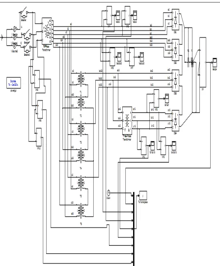
In closed loop system, the output voltage is obtained using the direct control of space vector modulation technique. The closed loop system is analyzed and discussed in this paper. The results of measurements of the system is also shown with certain specifications. The operating method is based on SVM(space vector modulation). Controller implementation is also done. The simulation verifies performance and applicability in proposed system. The closed loop system includes diode bridge rectifier, inductor connected in series, transformers, SVPWM (space vector pulse width modulation) technique.
Fig 4.closed loop control of 12-pulse rectifier
Fig5.Inputcurrentwaveform Fig 6. Closed Loop Output Voltage
Fig 7 controller circuit of 12-pulse rectifier.
IV.SIMULATION AND RESULTS
Relevant input and output voltage waveforms are shown, for rated power and voltages, which are in agreement with the expected results. Fig 6 shows the open loop control of 12-pulse rectifier. Fig 9 shows the closed loop control of 12-pulse rectifier involving spvm.
ISSN (Print) : 2320 – 3765 ISSN (Online): 2278 – 8875
I
nternational
J
ournal of
A
dvanced
R
esearch in
E
lectrical,
E
lectronics and
I
nstrumentation
E
ngineering
(An ISO 3297: 2007 Certified Organization)
Website: www.ijareeie.com
Vol. 6, Issue 2, February 2017
Fig9.Output voltage under breaker condition. Fig 10. Output for line to line voltage.
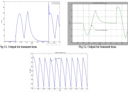
Fig 11. Output for transient time. Fig 12. Output for transient time.
V. CONCLUSION
This project deals with the novel scheme of control for a 12-pulse rectifier by having an LIT which have SPVM. The SPVM (space vector modulation) , control structure that are closed loop allows output voltage of direct control , basic operation principle are explained. The results and simulation of this control scheme are verified and presented. This current control scheme is a closed loop that allows main current, output voltage and gives high quality main current sinusoidal and also provides current magnitude controllability. Moreover, the power control is done directly and boost inductors will be investigated which are present in LIT.
REFERENCES
[1] F. J. Chivite-Zabalza, “High power factor rectification for aerospace systems,”Ph.D. dissertation, School Electr. Electron.Eng.,Univ. Manchester,Manchester, England, 2006.
[2] G. R. Kamath, B. Runyan, and R. Wood, “A compact autotransformerbased 12-pulse rectifier circuit,” in Proc. 27th IEEE Ind. Electron. Soc.Conf. (IECON), 2001, vol. 2, pp. 1344–1349.
[3] G Loganathan, D Rajkumar, M Vigneshwaran, R.Senthil Kumar, “An enhanced type effective partical swam intelligent for practical economic load dispatch,” Electrical Energy Systems (ICEES), 2014 IEEE 2nd, 2014
[4] J. W. Kolar, J. Minib¨ock, and M. Baumann, “Three-phase PWM power conversion—The route to ultra high power density and efficiency,” presented at the CPES Annu. Semin./Ind. Rev., Blacksburg VA, Apr. 27–29, 2003.
[5] J Gouthaman, R Bharathwajanprabhu, “Automated urban drinking water supply control and water theft identification system,” A Srikanth Students' TechnologySymposium (TechSym), 2011 IEEE, 87-91.
[6] K. Oguchi, G. Maeda, N. Hoshi, and T. Kubota, “Voltage-phase shifting effect of three-phase harmonic canceling reactors and their applications to three-level diode rectifiers,” in Proc. Conf. Record 34th IEEE IAS Annu.Meeting, 1999, vol. 2, pp. 796–803.
[7] Sundararaju K., A. Nirmal Kumar, “Cascaded Control of Multilevel Converter based STATCOM for Power System Compensation of Load Variation” International Journal of Computer Applications(0975 –8887) Volume 40– No.5, Pp30-35, 2012.
[8] N. R. Raju, A. Daneshpooy, and J. Schwartzenberg, “Harmonic cancellation for a twelve-pulse rectifier using dc bus modulation,” in Proc. Conf.Record 37th IEEE IAS Annu. Meeting, 2002, vol. 4, pp. 2526–2529.
[9] R. Karthikeyan ., Chenthur Pandian S Generalized space vector PWM algorithm for minimizing THD in hybrid multilevel inverters, International Review of Electrical Engineering.Vol.6,N.52011, pp 2094-2099
[10] R Karthikeyan, SC Pandian, “An efficient multilevel inverter system for reducing THD with Space Vector Modulation,” International Journal of Computer Applications 23 (2), 0975-8887
[11] Karthikeyan,R., and S.Chenthur Pandian. "A Novel 3-D Space Vector Modulation Algorithm for Cascaded Multi level Inverter."International Review ofElectrical Engineering, vol 6, issue 7, (2011).
[12] S.K.Nandhakumar and P.Alageswari, „Performance analysis of MPPT algorithms for PV array fed SEPIC converter‟ Pakistan Journal of Biotechnology., Vol. 13, pp. 342-346, 2016