Gain and Noise figure Performance of
Raman-SOA Hybrid Amplifier at Different Channel
Spacing using NRZ and RZ Modulation
Format
Neha Dharwal1, Anu Sheetal2, Karamdeep Singh3
PG Student, Dept. of ECE, Guru Nanak Dev University, Gurdaspur, Punjab, India1
HOD, Dept. of ECE, Guru Nanak Dev University, Gurdaspur, Punjab, India2
Incharge, Dept. of ECE, Guru Nanak Dev University, Amritsar, Punjab, India3
ABSTRACT: In this paper, 32×10Gb/s DWDM using Raman-SOA(semiconductor optical amplifier) hybrid amplifier has been investigated at different channel spacing (0.4nm, 0.8nm, 1.6nm) by using NRZ and RZ modulation format to obtain the gain and noise figure of hybrid amplifier. Raman-SOA hybrid amplifier (HA) is proposed and studied to improve the gain and noise figure of hybrid amplifiers. Different channel spacing are used for RamanSOA HA with -23dBm input signal power, length of 0.0003m for SOA and 10km length of Raman amplifier. It has been observed that as the channel spacing decreases, the performance drastically degrades owing to FWM effect.
KEYWORDS:RAMAN, SOA, DWDM, Gain, Noise Figure
I.INTRODUCTION
Now a days there is increase in demand for higher transmission capacity, to achieve the higher capacity DWDM system is the basic promising technology [1]. This technology cheaply solves the problem of increasing communication channels without deploying new cables. The conventional optical amplifiers, such as the erbium-doped fiber amplifier
(EDFA), the semiconductor optical amplifier (SOA) and the Raman amplifier are the vital components for DWDM systems [2, 3]. Raman amplifiers have attracted huge attention in recent years due to the fact that any wavelength, within the transparency window of an optical fiber, can be amplified by simply adjusting the pump wavelength [4]. Various Drawback of a Raman amplifier is that nonlinear effects such as stimulated Brillouin scattering, self-phase modulation, cross-phase modulation, and four-wave mixing degrade the signal when the amplifier has large output power [5].SOAs produces large amount of amplified spontaneous emission(ASE). Also gain dynamics cause signal distortions [6]. Raman amplifiers provide noise free amplification. In Raman amplifier spectrum can be changed by using different pumps and their frequencies [7]. To improve the drawbacks of different amplifiers they are used together by forming a hybrid amplifier (HA).
The combination of more than one optical amplifier in any configuration is called hybrid optical amplifier (HOA), that combine several amplifiers with different gain bandwidths to extend the gain bandwidth product of the optical
amplifiers. Mohammed N. Islam described that the net gain of the Raman-EDFA HOA (GHybrid) is the sum of the two individual gain of Raman and EDFA respectively [8]. Therefore, in the case of Raman-EDFA HOA the net gain is: GHybrid =GEDFA + GRaman (1)
between 7 and 8 dB. Also, due to the similar gain profile of these amplifiers, the expensive gain flattening techniques are exempt from achieving large gain flatness.
This paper propose a model of HOA (Raman-SOA) at different channel spacing such as 0.4, 0.8 and 1.6nm. The system is investigated for 32 channel DWDM system, and the results are further compared in the term of Gain and Noise Figure.
The paper is organized as follows: In section II, the setup of hybrid amplifier is described. In section III discusses the results and at last conclusions are made in section IV.
II. SYSTEM DESCRIPTION
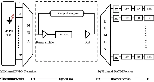
The system for 32 channel DWDM system at various channel spacing that are amplified by RAMAN-SOA hybrid amplifier is shown in Fig.1
amplifier is shown in Fig.1
λ1
λ
1λ
2.
.
λ
32Figure 3.1 schematic diagram of DWDM system
In this system, 32 channels are transmitted by using DWDM transmitter at 10Gb/s data rate using 0.4, 0.8 and 1.6nm channel spacing at a frequency of 1550nm. The power of input signal for each channel is taken as -23dBm using NRZ and RZ modulation format. All the 32 channels are multiplexed using WDM MUX and the signal thus obtained is used in WDM communication system. The gain, noise figure is obtained through Dual port WDM analyzer. Isolator is placed between Raman and wideband SOA because it allows the transmission of light in only one direction. It is typically used to prevent unwanted feedback into an optical oscillator, such as a laser cavity. Transmitted signals are multiplexed and launched in to optical fiber, where hybrid optical amplifiers (Raman-SOA) are used to amplify the signals. The various parameters for Raman amplifier are: Length = 10km, operating temperature = 300k, different pump wavelength (1405nm-1457nm) and different pump powers of 100mW. These amplified signals are then received by optical receivers. Optical receivers comprise of PIN photo detector, low pass Bessel’s filter and 3R regenerator.
Parameters of PIN photodiode are Dark current = 10nA and responsivity = 1A/W. Low pass Bessel filter having cut off frequency = 7.5GHz and order = 4.BER analyzer and spectrum analyzer are used as visualizer to obtain the value of
Q-D
E
M
U
X
Raman amplifier SOA
16/32 channel DWDM Transmitter 16/32 channel DWDM Receiver
Optical link
Transmitter Section Receiver Section
Isolator
Dual port analyzer
WDM
Tx
M
U
X
BER 3R
LPF
BER 3R
LPF
BER 3R
factor, BER, output power, eye diagrams and signal spectrums. In Dense wavelength division multiplexed system the channel spacing becomes denser but more wavelengths can be accommodated in same C Band (1530-1565nm). In case of 1.6nm, system would use 32 channels but as the channel spacing reduces to 0.8nm, system should use 64 channels and further channel spacing reduces to 0.4nm, system should use 32 channels.
III.RESULTS AND DISCUSSION
Case 1: Performance evaluation of Raman-SOA HOA by using NRZ modulation format
Fig. 2 shows the gain of HOA is plotted against the signal wavelength. It is clear that the maximum gain of 19.8dB has been reported at 1.6nm of channel spacing, similarly gain 17.26dB is obtained at 0.8nm and lowest gain 14.26dB at 0.4nm of channel spacing at a wavelength of 1500-1550nm and the results shows that as the channel spacing reduces, performance gets deteriorate due to non linear effect such as FWM and XPM
[
13].
Due to the gain dynamics induced by the optimized HOA, distortion of pulse shapes and crosstalk between channels are present. These crosstalk effects are due to the induced nonlinearities such as stimulated Raman scattering, four-wave mixing, self and cross-phase modulation, etc.
Fig.2 Gain vs Wavelength
Fig. 3 Noise Figure vs Wavelength
1500 1505 1510 1515 1520 1525 1530 1535 1540 1545 1550 10
11 12 13 14 15 16 17 18 19 20
Wavelength [nm]
G
a
in
[
d
B
]
0.4 nm 0.8 nm
1.6 nm
1500 1505 1510 1515 1520 1525 1530 1535 1540 1545 1550
-5 0 5 10
Wa ve le ngth [nm]
N
o
is
e
F
ig
u
re
[
d
B
]
0.4 nm 0.8 nm
From the results of gain, it can further be consolidated by observing the noise figure also. From Fig.3 the performance of noise figure can be evaluated. The largest values of noise figure at the signal wavelength range are found at 0.4nm of spacing while the lower values are found at higher channel spacing i.e. 1.6nm. The noise figure is likely to be opposite of gain of Raman-SOA hybrid amplifier.
Case 2: Performance evaluation of Raman-SOA HOA by using RZ modulation format
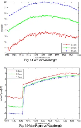
Graph of gain versus wavelength is shown in Fig 4. It is observed from the graph that maximum gain of 21dB has been reported at 1.6nm of channel spacing with less than <6dB noise figure at 1.6nm is obtained and the disturbance is more at lowest channel spacing i.e. 0.4nm. As the channel spacing decreases, gain also decreases that shows as the channel spacing reduces the performance of the system drastically degrades.
Fig. 4 Gain vs Wavelength
Fig. 5 Noise Figure vs Wavelength
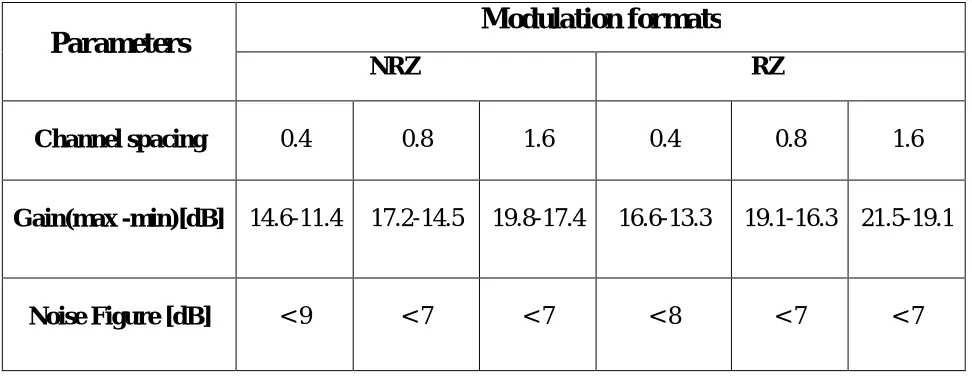
Table 1 Gain and noise figure comparison at different channel spacing for 32 channels
Parameters
Modulation formats
NRZ
RZ
Channel spacing
0.4
0.8
1.6
0.4
0.8
1.6
Gain(max -min)[dB]
14.6-11.4
17.2-14.5
19.8-17.4
16.6-13.3
19.1-16.3 21.5-19.1
Noise Figure [dB]
< 9
< 7
< 7
< 8
< 7
< 7
Table 1 shows the gain and noise figure comparison between the NRZ and RZ modulation format. In this the gain at maximum and minimum value is given at different channel spacing. That shows that as the channel spacing increases, gain decreases due to four wave mixing.
IV.CONCLUSION
In this paper, the comparison of NRZ and RZ modulation format is analyzed for Raman-SOA at Different channel spacing. The HOAs are one of the possible ways to amplify the broad gain bandwidth product with minimum gain variation among the channels. Maximum gain of 21.5 dB and 19.8 dB is obtained at 1.6nm of channel spacing by using RZ and NRZ modulation format. It is concluded that gain is maximum of using RZ modulation format with minimum NF and overall result shows that as the channel spacing reduces more channel can be accommodated in available bandwidth and effect of four wave mixing increases.
REFERENCES
[1] Govind P. Agarwal, “Fibre Optic Communication Systems”, John Wiley & sons, Inc. Publication, 2003.
[2] M.N. Islam, Raman amplifiers for telecommunications, IEEE J. Sel. Top. Quant.Electron 8 (May/June (3)), pp. 548–559. [3] M. L. Nielsen, K. Tsuruoka, T. Kato, et al., J. Lightwave Technol., 28, 837, 2010.
[4] Mohammed N. Islam, “Raman Amplifiers for Telecommunications”, Springer, New York, pp. 422, 2004.
[5] T. Sakamoto, S. Aozasa, M. Yamada, and M. Shimizu, “Hybrid fiber amplifiers consisting of cascaded TDFA and EDFA for WDM signals,” J. Lightwave Technol. 24, pp. 2287-2295, 2006.
[6] S. Singh, R.S. Kaler, Investigation of hybrid optical amplifiers for dense wavelength division multiplexed system with reduced spacing at higher bit rates, Fiber Integr. Opt. 31, pp. 208–220, 2012.
[7] V. Bobrovs, S. Olonkins, A. Alsevska, L. Gegere and G. Lvanovs, “Comparative performance of Raman-SOA and Raman-EDFA hybrid optical amplifiers in DWDM transmission systems,” International Journal of Physical Sciences, Vol 8, Issue 39, Pp 1898-1906, 2013.
[8] M.N. Islam, Raman amplifiers for telecommunications, IEEE J. Sel. Top. Quant.Electron. 8 (May/June (3)), 548–559, 2000
[9] S. Singh, R.S. Kaler, Performance evaluation of 64 × 10 Gbps and 96 × 10 Gbps DWDM system with hybrid optical amplifier for different modulation formats, Optik, 2199–2203, 2012.
[10] ju Han Lee, ypu Min Chang, Young Geun Han, Haeyang Chung, Sang Hyuck Kim, Sang Bae Lee, A detailed experimental study on single pump Raman/EDFA hybrid amplifirs: staic, dynamic, and system performance comparison, j. Lightwave Technol. 23, pp.3484-3493, 2005 [11] J. Masum-thomas, D. Crippa and A. Moroney, “A 70 wide S-band amplifier y cascading TDFA and Raman fiber amplifier,” in Optical Fiber
Communication Conf. and Exhibit. (OFC) (2002).
[12] G.P Agarwal, “fiber optic communication systems, “ john Wiley and sons, new York, 1997.
![Fig.2 Gain vs Wavelength Wavelength [nm]](https://thumb-us.123doks.com/thumbv2/123dok_us/7776507.1282609/3.595.159.430.345.760/fig-gain-vs-wavelength-wavelength-nm.webp)