ISSN (Print) : 2320 – 3765 ISSN (Online): 2278 – 8875
I
nternational
J
ournal of
A
dvanced
R
esearch in
E
lectrical,
E
lectronics and
I
nstrumentation
E
ngineering
(A High Impact Factor, Monthly, Peer Reviewed Journal)
Website: www.ijareeie.com
Vol. 7, Issue 10, October 2018
Adaptive the Modeling of BLDC Motor Based
on Fuzzy Logic and Genetic Algorithm
Er. Darshana Bharti, Dr. Pratibha Tiwari
M.Tech Scholar, Department of Electrical Engineering, Shepherd Institute of Engineering and Technology (SSET), Shuats, Allahabad, India
Assistant Professor, Department of Electrical Engineering, Shepherd Institute of Engineering and Technology (SSET), Shuats, Allahabad, India
ABSTRACT: Fuzzy logic controller has gained wide popularity in the application of motion controls for Brushless DC motors. Their performance is desirable, with auto-tuning. In this project, a selected Brushless DC motor is investigating the performance of a genetic algorithm and fuzzy logic controlled by the controller. An overshoot speed is observed together with settlers thereby confirming the behavior of a genetic algorithm and fuzzy logic controller. This is a matter of necessity to tune the fuzzy logic controller in order to achieve the desired performance. On the other hand, apply a fuzzy logic controller on Brushless DC motor is checked. With the application of appropriate expert rules, there is a minimum overshoot and settling time within the desired price. With the fuzzy Logic Controller, manual tuning is finished and intelligent tuning takes center stage with satisfactory performance. The speed control of Brushless DC motor is done using the genetic algorithm and FLC in the MATLAB environment. In addition, the dynamic characteristics of the BLDC motor (i.e. speed and torque) as well as the voltages of the streams and inverters components are analyzed easily by using the observed and developed models.
KEY WORDS- BLDC Motor, Electric Drive Simulation, Fuzzy Logic, Matlab/Simulink
I. INTRODUCTION
Recently, brushless DC Motor (BLDC) is very popular because of its attractive features such as high starting torque, high efficiency, low maintenance cost, lack of mechanical cutter, high speed operation, low volume to torque ratio, spark and electromagnetic disturbances, elimination of noise.
A BLDC motor is inside the building out of the DC motor. Capacity equals size and cutter and the absence of brushes is more likely than DC motor, reduces motor length. Therefore increases the lateral stiffness of the motor, allowing for higher speed. In brushless DC motor the essential power electronic converters are similar in the topology for inverters used in the induction motor drive in PWM. Nowadays brushless DC motors are used in various applications such as defense, industry, robotics, etc. In these applications, the motor should be precisely controlled in order to deliver the desired performance. Classical controller system needs accurate mathematical models and can perform well only under linear condition. Since the BLDC motor is highly paired non-linear multivariable system, it is difficult to obtain its exact mathematical model. Therefore there is a need for intelligent controller. So an attempt is made to develop fuzzy controller for the BLDC motor. Fuzzy logic controller (FLC) is capable of providing the required by high performance drive system without really requiring high accuracy mathematical models. FLC accommodates non-linearity without the use of mathematical models.The fuzzy logic controller uses fuzzy logic as a design method, which can be applied in linear system development for embedded controls. Simplicity and low-intensive mathematical design requirements are the most important features of FLC.
ISSN (Print) : 2320 – 3765 ISSN (Online): 2278 – 8875
I
nternational
J
ournal of
A
dvanced
R
esearch in
E
lectrical,
E
lectronics and
I
nstrumentation
E
ngineering
(A High Impact Factor, Monthly, Peer Reviewed Journal)
Website: www.ijareeie.com
Vol. 7, Issue 10, October 2018
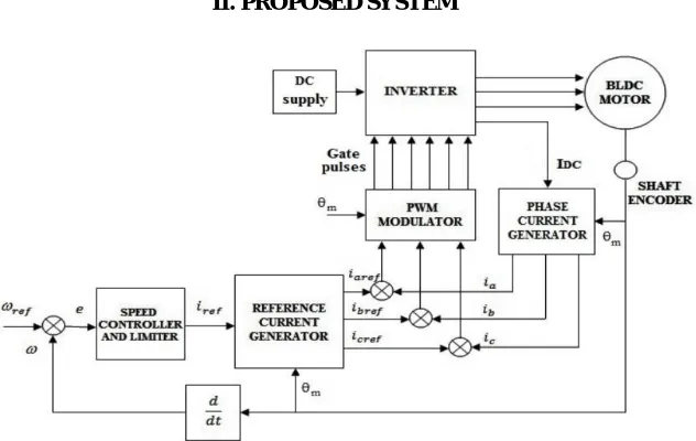
II. PROPOSED SYSTEM
Figure 1. Block Diagram of Brussless DC Motor
which use magnets to produce a magnetic flow in the air gaps. These permanent magnet machines are categorized into two types depending on the size of the flow density distribution and current stimulation. they are; A) Brushless turn is the current machines (BLAC), which equally motivates the rotating stat field back sinusoidal EMF. b) Brushless direct current machines (BLDC), which is EMF back to trapezoidal. The permanent magnet machines have an instate formed of copper Wind, distributed in three phases, and a rotor made of iron and permanent magnet. BLDC motors are widely categorized into three types depending on the magnet position in the rotor and they are surface mounted magnet, inset magnet and buried magnet. From these three types, surface mount Permanent magnet machines are cheaper because the rotor is only made of iron and the magnets are glued just afterwards. The position of magnets increases the mechanical strength of the rotor, and makes the machine suitable for very high speed operation through weak flow. In permanent magnet (puppy) machines, the unwillingness of the magnetic flux path varies according to the rotor position. Due to the installation, the control surface mount for a puppy machine is more difficult than the permanent magnet machine. Therefore, surface mount permanent magnet motors are more common in practical applications. The model provides a platform to design an electric system to estimate the rotor position of the motor. Given the non-sinusoidal flux delivery, the phase variable receives a model of the surface Mount BLDC motor. The equivalent circuit of the BLDC motor with three phase six switch inverters is shown in Fig 2. The model line of BLDC motor contains currents, line back emf and line voltage of the motor. In loop a-n-b of considering switches S1 and S4 are switched ON; the voltage between nodes ‘a’ and ‘n’ is given by
= ( ) + . ( ) + (1)
and voltage between node b and n is written as
= ( ) + . ( ) + (2)
The difference between phase voltages (Van and Vbn) constitutes to line voltage Vab
= ( − ) + . ( − ) + (3)
Similarly, line voltages Vbc and Vca are obtained by turning ON appropriate switches of the inverter.
ISSN (Print) : 2320 – 3765 ISSN (Online): 2278 – 8875
I
nternational
J
ournal of
A
dvanced
R
esearch in
E
lectrical,
E
lectronics and
I
nstrumentation
E
ngineering
(A High Impact Factor, Monthly, Peer Reviewed Journal)
Website: www.ijareeie.com
Vol. 7, Issue 10, October 2018
= ( − ) + . ( − ) + (5)
The above equation is re-written as
( − ) =− ( − )−1 +1 (6)
( − ) =− ( − )−1 +1 (7)
( − ) =− ( − )−1 +1 (8)
Hence, (2) and (3) are modified as
= 0 (9)
= 0 (10)
If the duration of the sample is significantly lower than the electrical and mechanical time constants then the EMF can be assumed to be persistent during each sample period and the time derivative of the back EMF equals zero as shown in (9) and (10). The third back EMF Eca, between the two phases (c and a) is deduced using
+ + = 0 (11)
The electromagnetic torque is given by
=( . + . + . ) (12)
The equation of motion is
=( − − . ) (13)
The amplitude of back EMF is proportional to the rotor speed, and is given by
= . (14)
This rectangular stator currently needs to produce a constant power torque while BLDC motor drives system speed to control. The small parameters jumble technique is developed with supervisors to speed measurements of position and current. Increasing the state of the art, which depends on electromagnetic force and flow linkages. It established performance forecasts on the broad range of operating conditions. The Hall effect sensor which senses the rotor position should dictate the controller's rotor rotation, because the controller which needs the rotor position relative to the stator coil.
ISSN (Print) : 2320 – 3765 ISSN (Online): 2278 – 8875
I
nternational
J
ournal of
A
dvanced
R
esearch in
E
lectrical,
E
lectronics and
I
nstrumentation
E
ngineering
(A High Impact Factor, Monthly, Peer Reviewed Journal)
Website: www.ijareeie.com
Vol. 7, Issue 10, October 2018
III. FUZZY LOGIC CONTROLLER
The FLC system uses fuzzy reasoning rules to establish a control mechanism for almost expert perception and judgment under the given conditions. The system is also known as fuzzy conclusion systems or projected reasoning systems or expert systems. The structure of a FLC can be described in Fig. 1.
i) Input Scaling or normalization: the current physical values of state variables i.e., which are often error (e) and change of error, are mapped into normalized values by Scaling factor Ge and Gdel.
ii) Fuzzification: each crisp current process state values (e and del)is converted to a fuzzy set to make it compatible with fuzzy set of process variable in the rule-antecedent.
iii) Inferencing (inference engine): The fuzzified input values are transferred to the inference engine to evaluate the control rules stores in rule base. And the result of this evaluation is a single fuzzy set or several fuzzy sets. Generally, logic rules which are the main facts to compose inference engine use AND (taking minimum value) or OR (taking maximum value) operators.
iv) Deffuzzication: defuzzification converts inference results of all active logic rules into a single crisp value in normalized domain. Defuzzification often use the maximum membership method, center of average method or center of gravity method.
v) Output scaling or denormalization: the defuzzified normalized control output is mapped into physical value by the output scaling factor Gu.
Fuzzy logic control (FLC) is a control algorithm based on a linguistic control strategy which tries to account human knowledge about how to control a system without the need of a mathematical model. Input and output are non-fuzzy values. The block diagram of FLC is shown in Fig. 3.
Figure 3 Fuzzy Logic Controller
Here Mamdani is used to type fuzzy reasoning motion controller. Speed error (E) and change of speed error (CE) are
inputs to fuzzy controller. The speed is calculated by comparing the error reference speed (ΩREF) with actual speed (Ω). The output of the controller is treated as a reference current (ref i).
ISSN (Print) : 2320 – 3765 ISSN (Online): 2278 – 8875
I
nternational
J
ournal of
A
dvanced
R
esearch in
E
lectrical,
E
lectronics and
I
nstrumentation
E
ngineering
(A High Impact Factor, Monthly, Peer Reviewed Journal)
Website: www.ijareeie.com
Vol. 7, Issue 10, October 2018
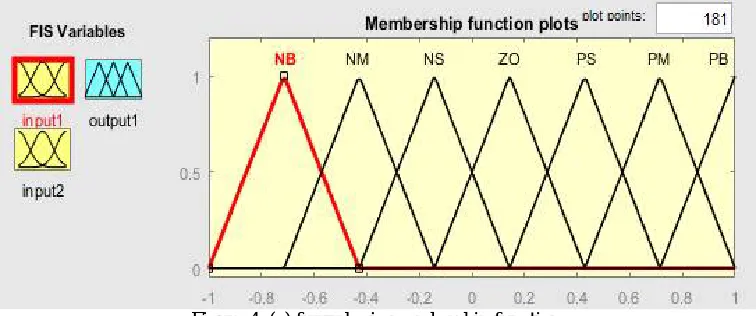
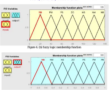
Figure 4. (b) fuzzy logic membership function
Fuzzy membership functions for (a) speed error (b) change in speed error (c) reference current
Rule base table used in the system
Table 1 Rule base table IV. GENETIC ALGORITHMS
ISSN (Print) : 2320 – 3765 ISSN (Online): 2278 – 8875
I
nternational
J
ournal of
A
dvanced
R
esearch in
E
lectrical,
E
lectronics and
I
nstrumentation
E
ngineering
(A High Impact Factor, Monthly, Peer Reviewed Journal)
Website: www.ijareeie.com
Vol. 7, Issue 10, October 2018
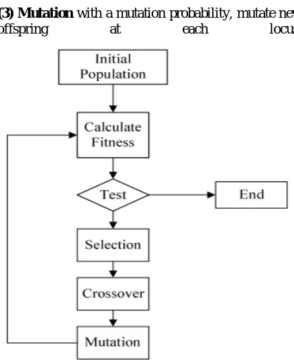
Initial Population GA starts with generating a random population of n chromosomes (suitable solutions for the problem). The population is composed by binary or real coded string chromosomes.
Calculate Fitness Evaluate the fitness value of each chromosome in the population.
Test If the end condition is satisfied, Stop, and return the best solution in the current population.
New population If the condition is not satisfied, a population is generated by following the steps below until a new population is complete.
(1) Selection Selects two parent chro mosomes from a population according to their fitness (the better fitness, the bigger chance to be selected).
(2) Crossover With a crossover probability, cross over the parents to generate new offspring. If no crossover was performed, the offspring is copied exactly the parents.
(3) Mutation with a mutation probability, mutate new offspring at each locus.
Figure 5. Flowchart of Genetic Algorithm
V. RESULTS AND DISCUSSION
Figure 6. Circuit Diagram BLDC
ISSN (Print) : 2320 – 3765 ISSN (Online): 2278 – 8875
I
nternational
J
ournal of
A
dvanced
R
esearch in
E
lectrical,
E
lectronics and
I
nstrumentation
E
ngineering
(A High Impact Factor, Monthly, Peer Reviewed Journal)
Website: www.ijareeie.com
Vol. 7, Issue 10, October 2018
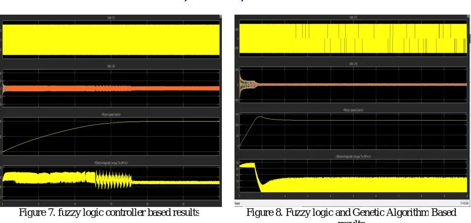
Figure 7. fuzzy logic controller based results Figure 8. Fuzzy logic and Genetic Algorithm Based results
Fuzzy Logic Controller has two input and every input carry seven member. And after that its generate rules as given Table 1. Based on its current error and FLC when using the FLC controller in the response circuit it performs operations and response time of the FLC taken more and shows in figure 7 and when FLC are update with Genetic Algorithm then the response time are more feasible. The drive speed response of the BLDC drive with the traditional PI controller response is slower than the FLC speed controller. The result is the drive response that proves to be faster with the FLC and GA controller than the FLC controller. The better response in the case of the FLC and GA controller is the great help for industrial applications.
VI. CONCLUSION
A new FLC and GA algorithm was proposed in this paper. The algorithm is based on the motor's speed profile and with GA. A new coding method, to control FLC tunes DC Brushless motor. After that, the algorithm was verified by tuning FLC a DC controls the BLDC motor . We have confirmed that calculating calculations using FLC and GA reduces costs and improves the convergence speed of optimal value. The response by using optimized FLC showed even better time settling, compared to the increase time the PID controllers use. In the future, after optimizing the algorithm, FLC and GA should be used to optimize the actual controller in the system. These systems are complex, mathematical models difficult to install or eternal noise, influenced by turbulence.
REFERENCES
1. Copperhill Technologies Corp. “A Comprehensible Guide to Servo Motor Sizing”, May 2007.
2. B.-K. Lee, T.-H. Kim, and M. Ehsani, (2003) “On the feasibility of fourswitch three-phase BLDC motor drives for low cost commercial applications: Topology and control,” IEEE Transaction on Power Electronics vol. 8, no. 1, pt. 1, pp. 164–172.
3. C.Chen, T.Hong, and V.S.Tseng. A comparison of different fitness functions for extracting membership functions usedin fuzzy data mining. In IEEE Symposium on foundations of computational intelligence, pages 550–555, 2007.
4. Y. Chiou and L.Lan. Genetic fuzzy logic controller: an iterative evolution algorithm with new encoding method. Fuzzy Sets and Systems, 152(3):617–635, 2005.
5. C.Liu, B.Li, and X.Yang. Fuzzy logic controller design based on genetic algorithm for dc motor. In IEEE Intl. Conf. On Electronics, Communications and Control, pages 2662–2665, 2011.
6. D.E.Goldberg. Genetic Algorithms in search, optimization, and machine learning. Addison-Wesley, 1989.
7. D.E.Goldberg. The Design of competent Genetic Algorithms: Steps towards a computational theory of innovation. Kluwer Academic, 2002. 8. Lekshmi A., Sankaran R., Ushakumari S. “Modelling and Simulation of PM Brushless DC Motor Based Spooler Drive System with Speed and
ISSN (Print) : 2320 – 3765 ISSN (Online): 2278 – 8875
I
nternational
J
ournal of
A
dvanced
R
esearch in
E
lectrical,
E
lectronics and
I
nstrumentation
E
ngineering
(A High Impact Factor, Monthly, Peer Reviewed Journal)
Website: www.ijareeie.com
Vol. 7, Issue 10, October 2018
9. P. Pillay and R. Krishnan,(1989) “Modeling, simulation, and analysis of permanent-magnet motor drives, part ii: The brushless dc motor drive,” IEEE Transaction on Industrial. Applications, vol. 25, no. 2, pp. 274–279.
10. D.Pelusi. Genetic-neuro-fuzzy controllers for second order control systems. In 5th European Symposium on Computer Modeling and Simulation, pages 12–17, 2011.
11. F.Herrera, M. Lozano, and J. L. Verdegay. Tuning fuzzy logic controllers by genetic algorithms. Inte. Jour. Of Approximate Reasoning, pages 299–315, 2013.
12. J.Jamaludin, N.A. Rahim, and W.P. Hew. Development of a self-tuning fuzzy logic controller for intelligent control of elevator systems. Engineering Applications of Artificial Intelligence, 22(8):1167–1178, 2009.
13. J.Zhang, N.Wang, and S.Wang. A developed method of tuning pid controllers with fuzzy rules for integrating process.In Proc.IEEE Of American Control Conference, pages 1109 –1114, 2004.
14. K.Belarbi, F. Titel, W. Bourebia, and K. Benmahammed. Design of mamdani fuzzy logic controllers with rule base minimisation using genetic algorithm. Engineering Applications of Artificial Intelligence, 17(7):875880, 2005.
15. L.Baron. Fuzzy decision support system knowledge base generation using a genetic algorithm. Inter. Journal of approximate reasoning, 24(2-3):125–148, 2001.
16. S. Ogasawara and H. Akagi, (2009) “An approach to position sensorless drive for brushless dc motors,” IEEE Transaction on Industrial Applications vol. 27, no. 5, pp.928–933.
17. H. Melkote and F. Khorrami, (1999) “Nonlinear adaptive control of directdrive brushless dc motors and applications to robotic manipulators,” IEEE Transaction on Mechatronics, vol. 4, no. 1, pp. 71–81.
18. H. Grabner, W. Amrhein,(2010) S. Silber, and W. Gruber, “Nonlinear feedback control of a bearingless brushless dc motor,” IEEE Transaction on Mechatronics, vol. 15, no. 1, pp. 40–47.
19. Seyed Mohammad Hossein Mousavi, Mehrdad Jafarboland, “Modeling the Dynamic Behavior of 9-Phase BLDC Motor and Examining the Effect of the Increased Number of Phases”, International Review of Modelling and Simulation, Vol. 5 no. 3, pp. 1254-1265, June 2012. 20. R. Shanmugasundram, K. M. Zakariah, and N. Yadaiah, (2009) “Digital implementation of fuzzy logic controller for wide range speed control
of brushless dc motor,” in Proceedings IEEE International Conference on Vehicle Electronics Safety, Pune, India, Nov. 10–12, pp. 119–124. 21. Y.-W. Tu and M.-T. Ho,(2012) “Robust second-order controller synthesis for model matching of interval plants and its application to servo
motor control,” IEEE Transaction on Control Systems Technology, vol. 20, no. 2, pp. 530–537.