Fast Calculation of Monostatic Radar Cross Section of Conducting
Targets Using Hierarchical Characteristic Basis Function Method
and Singular Value Decomposition
Can Xia1, 2, Wanqing You2, and Yufa Sun2, *
Abstract—A novel hierarchical characteristic basis function method (HCBFM) is proposed to calculate monostatic radar cross section based on singular value decomposition characteristic basis function method. In order to reduce the number of incident plane waves and accelerate the generation of characteristic basis functions (CBFs), an improved CBFs construction method is studied in this paper. Firstly, the target is partitioned with hierarchical approach, and at each incident plane wave, the high-level CBFs defined in large blocks are expressed as a linear combination of the previously generated low-level CBFs defined in the corresponding small blocks. Finally, the high-level CBFs in large blocks are orthogonalized by using singular value decomposition at multiple excitations, and a set of linearly independent CBFs can be obtained. Numerical results are given to demonstrate the accuracy and high efficiency of the proposed method.
1. INTRODUCTION
The method of moments (MoM) [1] is preferred in the solution of electromagnetic scattering problems, which converts integral equations into a dense linear matrix system. However, it places a considerable burden on the computational complexity and memory requirement when the electrically large target is analyzed. Recently, some iterative solvers, such as the multilevel fast multipole method (MLFMM) [2] based on addition theorem for spherical harmonics, the adaptive integral method (AIM) [3]: a fast iterative integral-equation solver through splitting the impedance matrix into near-field and far-field components, and the adaptive cross approximation (ACA) algorithm [4], which is a low-rank decomposition method, are developed to improve the calculation of the MoM. Unfortunately, these iterative methods suffer from convergence problems of ill-conditional matrices for electrically large targets under analysis. Especially, when the monostatic scattering problems are considered, the iterative process need be repeated for each excitation.
The characteristic basis function method (CBFM) [5, 6] is an iteration-free method, which can speed up the direct solution of the MoM matrix equations by dividing the target into multiple adjacent blocks. For each block, the CBFM constructs macro basis functions called characteristic basis functions (CBFs) which indicate the current distribution of each block. And the number of CBFs is smaller than that of the RWG basis functions proposed by Rao et al. [7] in 1982. In [8], a singular value decomposition based CBFM (SVD-CBFM) is proposed to solve multiple excitation electromagnetic scattering problems. An improved SVD-CBFM [9] is presented to further reduce the number of incident plane waves and CBFs. However, as the electrical size of target increases, the size of each block will become large with retaining a proper number of blocks. This will lead to the increase of unknowns of each block, and the construction of CBFs becomes very time consuming.
Received 16 November 2018, Accepted 16 January 2019, Scheduled 21 February 2019
* Corresponding author: Yufa Sun (yfsun [email protected]).
1 Maanshan Teacher’s College, Maanshan 243041, China. 2 Key Lab. of Intelligent Computing & Signal Processing, Ministry of
In order to accelerate generation of CBFs and calculation of the reduced matrix equation, hierarchical CBFM (HCBFM) is proposed in this paper. The target is firstly divided with hierarchical partitioning approach. For each incident plane wave, the CBFs defined in large blocks are expressed as a linear combination of the previously generated low-level primary characteristic basis functions (PCBFs) and secondary characteristic basis functions (SCBFs) defined in the relatively small blocks, which can avoid directly solving the CBFs in the large blocks. Finally, the high-level CBFs in large blocks are orthogonalized by using singular value decomposition (SVD) at multiple excitations, and a set of linearly independent CBFs can be obtained. Besides, the ACA algorithm is also employed to fill the impedance matrix of far field, which can further accelerate the matrix-vector multiplication procedure of generating SCBFs and constructing the reduced matrix.
2. FORMULATION
2.1. Conventional SVD-CBFM
The surface integral equation is usually transformed into the following matrix equation using MoM.
Z·J=E (1)
where Z is an N ×N impedance matrix; J and E are N ×1 current vector and excitation vector, respectively; andN is the number of unknowns. The CBFM firstly divides the target intoM adjacent blocks then constructs characteristic basis function on each block. Eq. (1) can be expressed as
⎡ ⎢ ⎢ ⎢ ⎣
Z11 Z12 . . . Z1M
Z21 Z22 . . . Z2M ..
. ... . . . ...
ZM1 ZM2 . . . ZMM
⎤ ⎥ ⎥ ⎥ ⎦ ⎡ ⎢ ⎢ ⎢ ⎣ J1 J2 .. . JM ⎤ ⎥ ⎥ ⎥ ⎦= ⎡ ⎢ ⎢ ⎢ ⎣ E1 E2 .. . EM ⎤ ⎥ ⎥ ⎥ ⎦ (2)
whereZij(i= 1,2. . . , M;j= 1,2, . . . M) is anNi×Nj impedance sub-matrix, andJi and Ei are the surface current vector and excitation vector, respectively.
In order to obtain a set of completely orthogonal CBFs, the SVD-CBFM needs to set large number of incident plane wave excitations in the direction of elevation and azimuth (θ and ϕ). Let Nθ and Nϕ indicate the number of samples in θ and ϕ, respectively. Considering two kinds of polarization, the total number of incident excitations is Np = 2NθNϕ, which are arranged in matrix ENiip. The PCBFs for each block under multiple plane wave excitations can be obtained by solving the following equation.
ZeiiJPii =EiiNp (i= 1,2,3. . . M) (3) whereZeiiis anNie×Nieextended self-impedance matrix, andJPii and ENiip areNie×Np current matrix and excitation matrix, respectively.
Usually, the number of plane wave excitations used to generate the CBFs will exceed the number of degrees of freedom associated with the block, and it is desirable to remove the redundancy in the basic functions by applying SVD. This is done by expressing the CBFs as
JPii =UWVT (4)
whereU is an Nie×ri orthogonal matrix, a complete set of CBFs of blocki. W is an ri×ri diagonal matrix, and V is anri×Np orthogonal matrix. Supposing thatJki is the kth column vector ofU, the currentJi of block ican be expressed as a linear combination of Jki as follows:
Ji=
ri
k=1 αk
iJki (i= 1,2,3. . . M) (5)
where k = 1,2,3 . . . ri, αki is an unknown coefficient to be determined. Multiplying both sides of Eq. (2) by the transpose ofJi, the reduced coefficient matrix can be expressed as
whereZRis a M
i=1 ri×
M
i=1
ri reduced matrix, andαandERare M
i=1
ri×1 coefficient vector and excitation
vector, respectively. The coefficient vector can be solved after the LU decomposition [10] to the reduced matrix, then the total current distribution of the target can be obtained.
2.2. The Improved SVD-CBFM
In order to reduce the number of incident plane waves, accelerate the generation of CBFs and the filling speed of the reduced matrix, the construction of CBFs is improved in [9]. In this method, the coupling effect among the different blocks is taken into account through calculating the SCBFs of each block, which greatly reduces the number of incident plane wave excitations. Let Hθ and Hϕ indicate the numbers of samples in θ and ϕ, respectively. Considering two kinds of polarization, the total number of incident plane wave excitations is Hp = 2HθHϕ(Hp Np). The PCBFs for each block under each new plane wave excitation can be obtained by solving the following equation:
ZeiiJPi =Eii(i= 1,2. . . M) (7) where Zeii is an Nie×Nie extended self-impedance matrix, and JPi and Eii are Nie×1 current vector and excitation vector, respectively. According to the Foldy-Lax multiple scattering equation, the first-order SCBFs of blocki are calculated by scattered fields due to the PCBFs on all blocks except from itself. Similarly, we can calculate the additional second-order SCBFs. These SCBFs can be written as follows [11]:
ZeiiJSi1 = −
M
j=1(j=i)
ZijJPj (i= 1,2. . . M) (8)
ZeiiJSi2 = −
M
j=1(j=i)
ZijJSj1(i= 1,2. . . M) (9)
Therefore, the real CBFs of blockican be obtained by solving Eqs. (7), (8), (9) and removing the extended part. Then a set of perfectly orthogonal CBFs for each block can be obtained by using the SVD procedure underHp incident wave excitations.
2.3. The Hierarchical CBFM
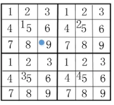
It is well known that the target needs to be first divided into multiple blocks when the CBFM is applied, but the size of the blocks has a great impact on computational time and storage consumption. In order to achieve the minimum calculation time, the numbers of blocks and unknowns N should be satisfied withM ≈0.9N1/3according to [12]. However, when the electrically large target is analyzed, it is usually divided into large blocks for improving the efficiency of calculation. The larger the size of blocks is, the smaller the reduction matrix which can be easily solved [13] is. Inevitably large subdomain contains more unknowns, and the procedure of generating CBFs will become very time consuming. In order to mitigate this problem, a novel HCBFM is proposed in this paper. In HCBFM, the electrically large target is firstly divided with hierarchical partitioning approach, and at each incident plane wave, the high-level CBFs defined in large block are expressed as a linear combination of the previously generated low-level CBFs defined in the corresponding small block, which can avoid directly solving the CBFs in the large block. Suppose that the target is firstly divided into M blocks, then each block is subdivided into N subdomains, and these subdomains can be further divided until the lowest level subdomains contain a few of RWG basis functions. For instance, as shown in Fig. 1, the target is firstly divided into four (M = 4) blocks called the second-level. Each block is subdivided into nine (N = 9) subdomains, called the first-level. The solid dot denoted as 1{9} in Fig. 1 stands for the ninth subdomain of the first block.
Figure 1. Hierarchical analysis of a target.
first-level extended small subdomain i{k}(i= 1,2 . . . M;k= 1,2 . . . N) are expressed as:
Zi{k}i{k}JiP{k} =Eri{k} (10) where Zi{k}i{k} is the self-impedance of the extended subdomain k in the block i, and
Eri{k}(r = 1,2 . . .2HθHϕ) is the rth incident plane wave excitation vector. Considering the mutual effects with other first-level small subdomains, the first-order SCBFs and the second-order SCBFs of first-level extended small subdomain kin the block iare generated as
Zi{k}i{k}JSi{1k} = −
N
h=1(h=k)
Zi{k}i{h}JPi{h} (11)
Zi{k}i{k}JSi{2k} = −
N
h=1(h=k)
Zi{k}i{h}JSi{1h} (12)
whereZi{k}i{h}is a mutual impedance matrix between subdomainkandh(h= 1,2,3. . . N) in the block i. The linear combination of the PCBFs and SCBFs after removing the extended portion can indicate the characteristic basis function of subdomainkin the block iunder the rth incident wave excitation
Jri{k} =ai{k}JPi{k}+bi{k}JSi{1k}+ci{k}JSi{2k} (13) Then constructing a reduced matrix equation of N small subdomains according to Eq. (6), the current coefficientsai{k},bi{k} andci{k} can be obtained by directly solving the reduced matrix equation. ai{k}, bi{k}, andci{k}are substituted into Eq. (13), and the real current of the subdomaini{k}can be obtained under therth incident wave excitation. Therefore, superimposing the currents ofN small subdomains, the current response of the second-level blockiunder the rth incident wave excitation can be achieved as:
Jri =
N
k=1
Jri{k} (14)
Then Ji of the second-level block i under multiple incident excitations are compressed by using SVD, and a set of linearly independent CBFs can be obtained. Finally, constructing a reduced matrix equation of M blocks on the second level in the same way, we can get the surface current of the target by direct solver.
In the HCBFM, the matrix-vector multiplication procedures of generating SCBFs and constructing the reduced matrix are also time consuming. In order to further improve the efficiency of calculation, the ACA algorithm [14] is also used to speed up the calculation of each level impedance matrix of far field.
3. NUMERICAL RESULTS AND DISCUSSIONS
256 GB RAM PC. The compiler used is Code::Blocks. The ACA and SVD threshold are set to 10−3, and the second-order SCBFs are chosen in the paper. We use the relative error of the RCS to estimate the accuracy of the proposed method, and the relative error is defined as follows:
Err(%) = 100×
n
RCSpm−RCSref2
n
RCSref2 (15)
where RCSpm is the RCS provided by the proposed method, and RCSref is the RCS provided by the FEKO.
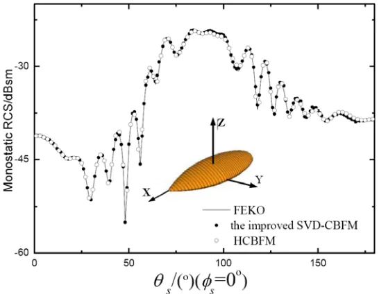
Firstly, monostatic RCS for a 252.3744-mm PEC almond is calculated at the incident frequency of 7 GHz, and the incident angle is set to θi = 0◦−180◦, ϕi = 90◦. The almond is divided into 6236 triangular patches, and the number of unknowns is 15950, which is divided into 48 first-level blocks and 12 second-level blocks, and each block is extended 0.05λon the first-level and 0.15λon the second-level in all directions. The monostatic RCSs in VV polarization calculated by the improved SVD-CBFM and HCBFM are shown in Fig. 2. In the two methods, the number of incident plane waves is set to Nθ = Nϕ = 8. When the improved CBFM is applied, the number of generated CBFs is 384 on each block, which can obtain about 82 CBFs after SVD, and the dimension of the reduced matrix is 988×988. But when the HCBFM is applied, the number of generated CBFs is 128 on each second-level block, which can obtain about 75 CBFs after SVD, and the dimension of the reduced matrix is 900×900, which is decreased about 9% compared to the previous method. It can be seen from Fig. 2 that the RCSs calculated by the two methods agree well with calculation results of the FEKO.
Figure 2. Monostatic RCS of the PEC almond inV V polarization.
Table 1 shows the computational time and relative error of the two methods. It can be found that the HCBFM outperforms the improved SVD-CBFM in computation time under the equivalent precision.
Table 1. CPU time and relative error of the PEC almond.
Methods CBFs
generation
reduced matrix
filling total time
relative error (%) Improved
SVD-CBFM 1157s 2739s 3903s 0.18
HCBFM 557s 2023s 2585s 1.09
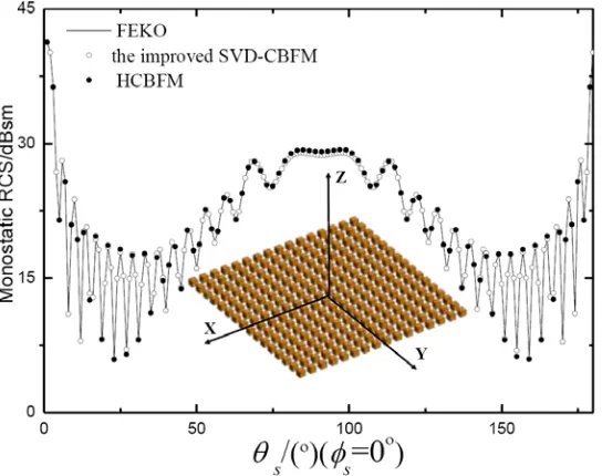
about 114 CBFs after SVD, and the dimension of the reduced matrix is 1824×1824. But when the HCBFM is applied, the number of generated CBFs is 160 on each second-level block, which can obtain about 106 CBFs after SVD, and the dimension of the reduced matrix is 1692×1692, which is decreased efficiently compared to the previous method. It can be seen from Fig. 3 that the RCSs calculated by the two methods agree well with calculation results of the FEKO. The computational time and relative error of the two methods are shown in Table 2.
Figure 3. Monostatic RCS of 256 discrete conducting cubs inHH polarization.
Table 2. CPU time and relative error of 256 discrete conducting cubs.
Methods CBFs generation reduced matrix filling total time relative error (%)
Improved CBFM 4504s 36809s 41345s 0.55
HCBFM 1933s 13811s 15776s 1.06
4. CONCLUSION
ACKNOWLEDGMENT
This work is supported by the National Natural Science Foundation of China (No. 61172020) and the Natural Science Research Project of Anhui provincial Education Department (No. KJ2015A436).
REFERENCES
1. Harrington, R. F., “Field computation by moment methods,” IEEE Press, 1993.
2. Song, J., C. C. Lu, and W. C. Chew, “Multilevel fast multipole algorithm for electromagnetic scattering by large complex objects,” IEEE Transactions on Antennas and Propagation, Vol. 45, No. 10, 1488–1493, 1997.
3. Bleszynski, E., M. Bleszynski, and T. Jaroszewicz, “Adaptive integral method for solving large-scale electromagnetic scattering and radiation problems,”Radio Science, Vol. 31, No. 5, 1225–1251, 1996.
4. Zhao, K., M. N. Vouvakis, and J. F. Lee, “The adaptive cross approximation algorithm for accelerated method of moments computations of EMC problems,” IEEE Transactions Electromagnetic Compatibility, Vol. 47, No. 4, 763–773, 2005.
5. Prakash, V. V. S. and R. Mittra, “Characteristic basis function method: A new technique for efficient solution of method of moments matrix equations,” Microwave and Optical Technology Letters, Vol.36, No. 2, 95–100, 2003.
6. Mittra, R., G. Bianconi, and C. Pelletti, “A Computationally efficient technique for prototyping planar antennas and printed circuits for wireless applications,” Proceedings of the IEEE, Vol. 100, No. 7, 2122–2131, 2012.
7. Rao, S. M., D. R. Wilton, and A. W. Glisson, “Electromagnetic scattering by surfaces of arbitrary shape,” IEEE Transactions on Antennas and Propagation, Vol. 30, No. 3, 409–418, 1982.
8. Lucente, E., A. Monorchio, and R. Mittra, “An iteration-free MoM approach based on excitation independent characteristic basis functions for solving large multiscale electromagnetic scattering problems,” IEEE Transactions on Antennas and Propagation, Vol. 56, No. 4, 999–1007, 2008. 9. Wang, Z. G., Y. F. Sun, and G. H. Wang, “Analysis of electromagnetic scattering from perfect
electric conducting targets using improved characteristic basis function method and fast dipole method,”Journal of Electromagnetic Waves and Applications, Vol. 28, No. 7, 893–902, 2014. 10. Shaeffer, J., “Direct solve of electrically large integral equations for problem sizes to 1 M unknowns,”
IEEE Transactions on Antennas and Propagation, Vol. 56, No. 8, 2306–2313, 2008.
11. Sun, Y. F., C. H. Chan, R. Mittra, and L. Tsang, “Characteristic basis function method for solving large problems arising in dense medium scattering,” IEEE Antennas and Propagation Society International Symposium, Vol. 2, 1068–1071, 2003.
12. Konno, K., Q. Chen, and K. Sawaya, “Optimization of block size for CBFM in MoM,” IEEE Transactions on Antennas and Propagation, Vol. 60, No. 10, 4719–4724, 2012.
13. Laviada, J., F. Las-Heras, M. R. Pino, and R. Mittra, “Solution of electrically large problems with multilevel characteristic basis functions,” IEEE Transactions on Antennas and Propagation, Vol. 57, No. 10, 3189–3198, 2009
14. Tamayo, J. M., A. Heldring, and J. M. Rius, “Multilevel adaptive cross approximation (MLACA),”