IJEDR1504039
International Journal of Engineering Development and Research (www.ijedr.org)265
Arduino Based Sonar
1Sanjana V Kalyanappagol,2Nemichandra P Dept. of Electronics and Communication 1BMS College Of Engineering,Bangalore,India
________________________________________________________________________________________________________
Abstract- The field of electronics and especially Embedded systems and micro controllers have always been a fascination. After learning about some of the basic sensors It was greatly disappointing that there was no Sonar or a Radar sensor and plotter. .This project gave us an excellent opportunity to build a sonar sensor.A practical Sonar or Radar is huge, operate at very high power levels, have very quick responsive circuits and have a range of up to 400KM.It is obviously impossible to build one at this stage so a miniature of a sonar was built to learn about its working, characteristics and limitation. This project culminates with our best and honest efforts to build a miniature Sonar based on Arduino Micro Controller.
IndexTerms–Arduino, Sonar, Detect objects, Co-ordinates
________________________________________________________________________________________________________
I.INTRODUCTION
Literature Survey
Sonar (originally an acronym for SO und Navigation And Ranging) is a technique that uses sound propagation (usually underwater, as in submarine navigation ) to navigate, communicate with or detect objects on or under the surface of the water, such as other vessels. Two types of technology share the name "sonar": passive sonar is essentially listening for the sound made by vessels; active sonar is emitting pulses of sounds and listening for echoes. Sonar may be used as a means of acoustic location and of measurement of the echo characteristics of "targets" in the water. Acoustic location in air was used before the introduction of radar . Sonar may also be used in air for robot navigation, and SODAR (an upward looking in-air sonar) is used for atmospheric investigations. The term sonar is also used for the equipment used to generate and receive the sound. The acoustic frequencies used in sonar systems vary from very low (infrasonic ) to extremely high ( ultrasonic). The study of underwater sound is known as underwater acoustics or hydro acoustics .
History
Although some animals (dolphins and bats) have used sound for communication and object detection for millions of years, use by humans in the water is initially recorded by Leonardo da Vinci in 1490: a tube inserted into the water was said to be used to detect vessels by placing an ear to the tube. In the 19th century an underwater bell was used as an ancillary to lighthouses to provide warning of hazards.The use of sound to 'echo locate' underwater in the same way as bats use sound for aerial navigation seems to have been prompted by the Titanic disaster of 1912. The world's first patent for an underwater echo ranging device was filed at the British Patent Office by English meteorologistLewis Richardson a month after the sinking of the Titanic, [2] and a German physicist Alexander Behm obtained a patent for an echo sounder in 1913.
Principle of active sonar
IJEDR1504039
International Journal of Engineering Development and Research (www.ijedr.org)266
although the beam may be rotated, relatively slowly, by mechanical scanning. Particularly when single frequency transmissions are used, the Doppler effect can be used to measure the radial speed of a target. The difference in frequency between the transmitted and received signal is measured and converted into a velocity. Since Doppler shifts can be introduced by either receiver or target motion, allowance has to be made for the radial speed of the searching platform.Passive sonar
Passive sonar listens without transmitting. It is often employed in military settings, although it is also used in science applications, e.g. , detecting fish for presence/absence studies in various aquatic environments - see also passive acoustics and passive radar . In the very broadest usage, this term can encompass virtually any analytical technique involving remotely generated sound, though it is usually restricted to techniques applied in an aquatic environment.
Passive sonar systems may have large sonicdatabases , but the sonar operator usually finally classifies the signals manually. A computer system frequently uses these databases to identify classes of ships, actions (i.e. the speed of a ship, or the type of weapon released), and even particular ships. Passive sonar on vehicles is usually severely limited because of noise generated by the vehicle. For this reason, many submarines operate nuclear reactors that can be cooled without pumps, using silent convection, or fuel cells or batteries , which can also run silently. Vehicles' propellers are also designed and precisely machined to emit minimal noise. High-speed propellers often create tiny bubbles in the water, and this cavitation has a distinct sound.The sonar hydrophones may be towed behind the ship or submarine in order to reduce the effect of noise generated by the watercraft itself. Towed units also combat the thermocline , as the unit may be towed above or below the thermocline .The display of most passive sonars used to be a two-dimensional waterfall display . The horizontal direction of the display is bearing. The vertical is frequency, or sometimes time. Another display technique is to colour-code frequency-time information for bearing. More recent displays are generated by the computers, and mimic radar -type plan position indicator displays Unlike active sonar, only one way propagation is involved. Because of the different signal processing used, the minimum detectable signal to noise ratio will be different.
The Sonar built in this project is an active sonar since it produces its own Pings to locate the object. Some of the major applications of Sonar are
‒ Underwater Communication ‒ Submarine Navigation ‒ Military Application ‒ Hand Held Sonar ‒ Intercept Sonar ‒ Fisheries ‒ Echo Sounding ‒ Net Location ‒ Vehicle Location
‒ Water Velocity measurement ‒ Wave Measurement
‒ Bathymetric Mapping ‒ Sub Bottom profiling
Scope of The Project
This Project has a scope of providing a whole new sensor which not only has better field of view and angular coverage but output data is represented in an easily understandable manner.
This project also has a future scope to be integrated to autonomous robots for obstacle detection and terrain mapping.With further enhancements, moving objects can be tracked and pin pointed.
Problem Definition
There are many sensors which can be interfaced with a Micro Controller such as Ping Sensor which can measure distance ,or the proximity sensor which can detect motion, Vibration sensor to detect vibrations.But there was no sensor which can detect the objects surrounding it and plot their co-ordinates on a screen!
Thus the problem definition is to detect the various objects surrounding the device and plot their co-ordinates and distances from the object on a screen.
II.SOLUTION PROPOSED
Experimental Setup
IJEDR1504039
International Journal of Engineering Development and Research (www.ijedr.org)267
Fig 1 The PIR SensorThe passive infrared sensor can detect moving objects at ranges of about 5-10 cm but it was found to be not suitable since it cannot detect stationary objects and has very limited range.
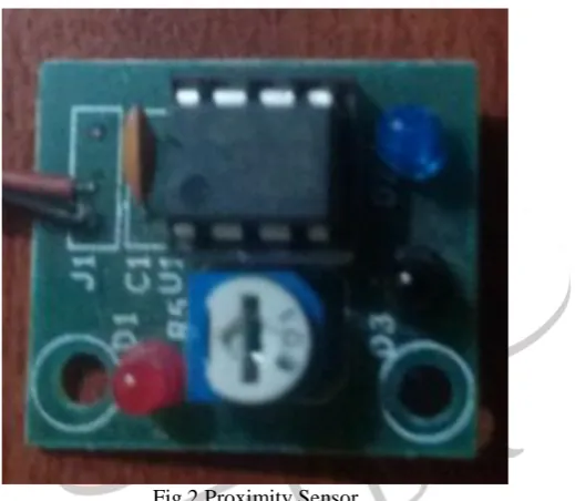
Fig 2 Proximity Sensor
This sensor detects light reflected from an object to detect its presence. It is widely used in line follower robots.But the shortcoming was its limited range,it can only work when object is very close ,below 5cm.
Ultrasonic (Ping) Sensor
This sensor has a range of four meters but its focus its field of view is very limited, so it was mounted on a servo motor to provide required field of motion
Objective/Goals
The goal of this project was to build an Arduino based miniature Sonar and to Study its working, capabilities and drawbacks.
IJEDR1504039
International Journal of Engineering Development and Research (www.ijedr.org)268
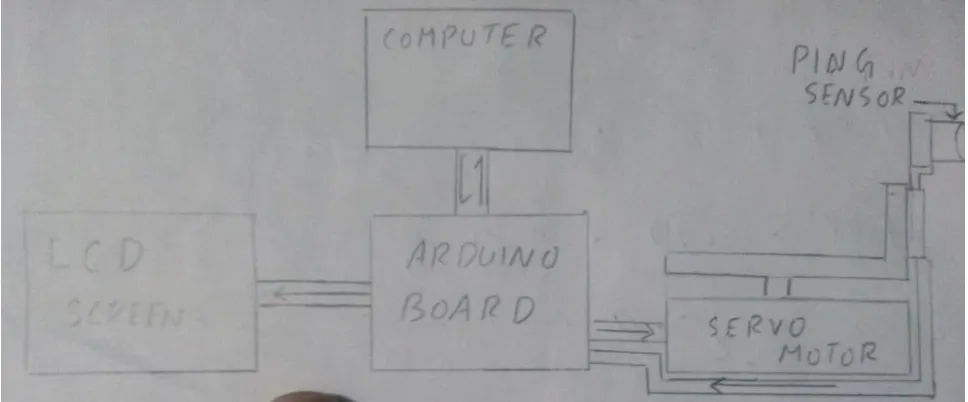
Fig 3 Block DiagramIII.HARDWARE DESIGN
Component Description
Fig 4 ARDUINO UNO R3
The Arduino UNO R3 is a microcontroller board based on theATmega328. It has 14 digital input/output pins (of which 6 canbe used as PWM outputs), 6 analog inputs, a 16 MHz crystal oscillator, a USB connection, a power jack, an ICSP header, anda reset button. It contains everything needed to support the microcontroller; simply connect it to a computer with aUSBcable or power it with a AC-to-DC adapter or battery to getstarted. The UNO differs from all preceding boards because it does not use the FTDI USB-to-serial driver chip. Additional features coming with the REV3 version are:ATmega16U2 instead of 8U2 as USB-to-Serial converter.1.0 pin out: added SDA and SCL pins for TWI communication placed near to the AREF pin and two other new pins placed near to the RESET pin, the IOREF that allow the shields to adapt to the voltage provided from the board and the second one is a not connected pin, that is reserved for future purposes. Stronger RESET circuit
Technical Specs
Microcontroller ATmega328 Operating Voltage 5V
Input Voltage (recommended) 7-12V Input Voltage (limit) 6-20V Digital I/O Pins 14 PWM Digital I/O Pins 6 Analog Input Pins 6 DC Current per I/O Pin 40 mA DC Current for 3.3V Pin 50 mA Flash Memory 32 KB Flash Memory for Bootloader 0.5 KB SRAM 2 KB EEPROM 1 KB Clock Speed 16 MHz
IJEDR1504039
International Journal of Engineering Development and Research (www.ijedr.org)269
Width 53.4 mmWeight 5 g
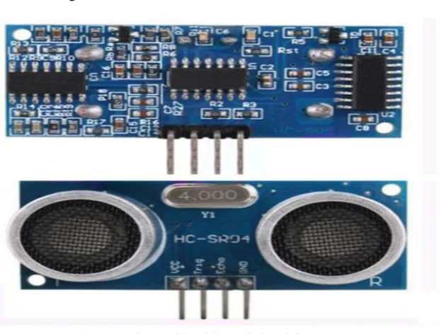
Fig 5 HCSR-04 PING SENSOR
HC-SR04 is an ultrasonic ranging module that provides 2 cm to 400 cm non-contact measurement function. The ranging accuracy can reach to 3mmand effectual angle is < 15°. It can be powered from a 5V power supply.
HC-SR04 Specifications Working Voltage: DC 5V Working Current:15mA Working Frequency: 40Hz Max Range:4m
Min Range:2cm
Measuring Angle: 15 degree
Trigger Input Signal: 10µS TTL pulse Dimension 45 * 20 * 15mm
Fig 6 EMAX ES80A SERVO MOTOR
This is the Emax ES08A analog micro servo. This servo uses the standard 3pin PWM connectorso you can easily plug it into your flight controller,orreciever directly. This servo comes with 3 servohorns, and the requires screws. This servo is compatible with the GoProcamera Gimbal
IJEDR1504039
International Journal of Engineering Development and Research (www.ijedr.org)270
Torque: 1.5/1.8Kg.cm 20.8/24.9oz.in(4.8V/6V)Speed: 0.12/0.10sec/60°
Size: 32 x 11.5 x 24mm / 1.25 x 0.45 x 0.94 Weight: 8.5g / 0.29oz
Dead band width: 1-2 usec Wire length: 23cm
connector type: Futaba/JR compatible
Fig 7 GROVE RGB LCD
This Grove enablesyou to set the colour to whatever you like via the simple andconcise Grove interface. It takes I2C as communication methodwith your microcontroller. So number of pins required for dataexchange and backlight control shrinks from ~10 to 2, relievingIOs for other challenging tasks. Besides, Grove - LCD RGBBacklight supports user-defined characters. Built-in English and Japanese fontsI2C communication, uses only two IOsAutomatic power-on reset
Specification
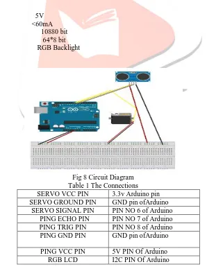
Input Voltage: 5V Operating Current: <60mA CGROM: 10880 bit CGRAM: 64*8 bit Colour: RGB Backlight
Circuit Diagram
Fig 8 Circuit Diagram Table 1 The Connections SERVO VCC PIN 3.3v Arduino pin SERVO GROUND PIN GND pin ofArduino
SERVO SIGNAL PIN PIN NO 6 of Arduino PING ECHO PIN PIN NO 7 of Arduino PING TRIG PIN PIN NO 8 of Arduino PING GND PIN GND pin ofArduino
PING VCC PIN 5V PIN Of Arduino
IJEDR1504039
International Journal of Engineering Development and Research (www.ijedr.org)271
IV.SOFTWARE DESIGN
Software Architecture
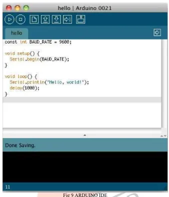
Fig 9 ARDUINO IDE
Arduino IDE is an open source software created by the developers of the Arduino Micro Controllers. The IDE is really simple. It mainly consists of an editor, a compiler, a loader, and a serial monitor. The Arduino programming language is very similar to Basic C programming with a few added functions.
Fig 10
You can see the IDE’s toolbar that gives you instantaccess to the functions you’ll need most:
‒ With the Verify y button, you can compile the program that’s currently in the editor. So, in some respects, “Verify” is a bit of a misnomer, because clicking the button does not only verify the program syntactically. It also turns it into a representation suitable for the Arduino board.
‒ The New button creates a new program by emptying the content of the current editor window. Before that happens, the IDE gives you the opportunity to store all unsaved changes.
IJEDR1504039
International Journal of Engineering Development and Research (www.ijedr.org)272
‒ When you click the Upload button, the IDE compiles the currentProgram and uploads it to the Arduino board you havechosen in.
Arduino Code #include <Wire.h> #include "rgb_lcd.h" rgb_lcdlcd;
#define ECHOPIN 7 // Pin to receive echo pulse #define TRIGPIN 8
#include <Servo.h>
Servo myservo; // create servo object to control a servo intpos = 0; // variable to store the servo position void setup() {
myservo.attach(6); // attaches the servo on pin 9 to the servo object pinMode(6,OUTPUT);
pinMode(ECHOPIN, INPUT); pinMode(TRIGPIN, OUTPUT);
}
void Print (int R , int T) {
Serial.print(R);Serial.print(", "); Serial.print(T);Serial.println("."); delay(100);
}
float Distance () {
digitalWrite(TRIGPIN, LOW); delayMicroseconds(2);
digitalWrite(TRIGPIN, HIGH); delayMicroseconds(10); digitalWrite(TRIGPIN, LOW); // Distance Calculation float TEMP =27;
float factor = (20000/331.5 +.6*TEMP); float distance = pulseIn(ECHOPIN, HIGH); distance= distance/factor;
return(distance); }
void loop() {
myservo.write(0); // tell servo to go to position in variable 'pos' delay(2000);
for(pos = 0; pos<=180; pos+=3) // goes from 0 degrees to 180 degrees {
myservo.write(pos); // tell servo to go to position in variable 'pos' Print(Distance() , pos);
lcd.begin(16, 2); floatcolorR; floatcolorG; floatcolorB;
lcd.setRGB(colorR, colorG, colorB); lcd.setCursor(0,0); lcd.print(Distance()); lcd.setCursor(0,1); lcd.print(pos); if(Distance()<=10) {
colorR = 255;//RED backlight if ditance is less than 10 cm colorG = 0;
IJEDR1504039
International Journal of Engineering Development and Research (www.ijedr.org)273
}else if(Distance()>=50) {
colorR = 0;
colorG= 255;//Green Backlight if distance is above 50 cm colorB = 0;
} else { colorR =0; colorG =0;
colorB =255;//BLUE backlight if distance is above 10 below 50 cm }
delay(50); }
for(pos = 180; pos>=0; pos-=3) // goes from 180 degrees to 0 degrees {
myservo.write(pos); // tell servo to go to position in variable 'pos' Print(Distance() , pos);
lcd.begin(16, 2); floatcolorR; floatcolorG; floatcolorB;
lcd.setRGB(colorR, colorG, colorB); lcd.setCursor(0,0); lcd.print(Distance()); lcd.setCursor(0,1); lcd.print(pos); if(Distance()<=10) {
colorR = 255; //RED backlight if ditance is less than 10 cm colorG = 0;
colorB = 0;
}
else if(Distance()>=50) {
colorR = 0;
colorG= 255;//Green Backlight if distance is above 50 cm colorB = 0;
} else { colorR =0; colorG =0;
colorB =255;//BLUE backlight if distance is above 10 below 50 cm
}
delay(50); }
IJEDR1504039
International Journal of Engineering Development and Research (www.ijedr.org)274
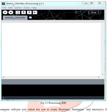
Processing IDEFig 11 Processing IDE
Processing is a computer software tool which lets you to create Drawings, Animation and interactive Graphics. It is the brainchild of “Casey Reas and Ben Fry”.It is verysimilar to Arduino IDE and open source software which can be used by the programmer with great modification.Processing was created to make programminginteractive graphics easier. The makers were frustrated with how difficult it was to write this type ofsoftware with the programming languages ,theyusually used (C++ and Java) and were inspiredby how simple it was to write interestingprograms with the languages of our childhood(Logo and BASIC). They were most influencedby Design By Numbers (DBN).
Processing Code
importprocessing.serial.*; Serial port;
Serial port2; String data = ""; String Radius = ""; String Theta = ""; int index = 0; float distance = 0; float angle = 0; float pi = 22.0/7; PFont f;
void setup() {
size(1000,1000);
background(255,255,255); ellipse(500,500,1000,1000); line(500,0,500,1000); line(0,500,1000,500); line(500,500,1000,0); line(500,500,0,0);
IJEDR1504039
International Journal of Engineering Development and Research (www.ijedr.org)275
port = new Serial(this, "COM20", 9600);port.bufferUntil('.'); }
void draw() {
}
voidserialEvent(Serial port) {
data = port.readStringUntil('.');
data = data.substring(0, data.length() - 1); index = data.indexOf(",");
Radius = data.substring(0, index);
Theta = data.substring (index+1 ,data.length()); translate(500,500);
point (0,0);
distance = float(Radius); angle = float(Theta) /180 * pi; fill(30,200,30);
ellipse(distance * cos(angle) , -1 * distance * sin(angle) , 5,5); textFont(f,16);
fill(255,0,0);
text(distance,distance * cos(angle) , -1 * distance * sin(angle)); }
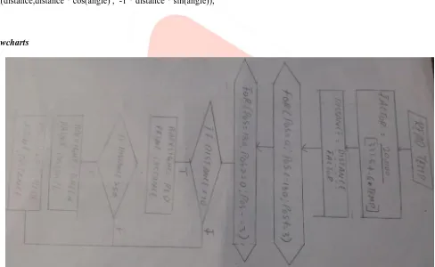
Flowcharts
Fig 12 Flowchart
V.PROJECT INTEGRATION
IJEDR1504039
International Journal of Engineering Development and Research (www.ijedr.org)276
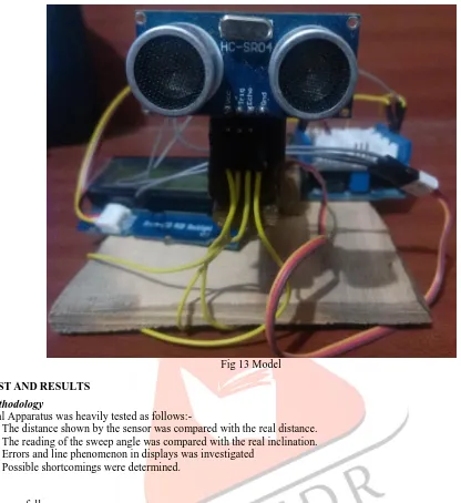
Fig 13 ModelVI.TEST AND RESULTS
Test Methodology
The Final Apparatus was heavily tested as follows:-
‒ The distance shown by the sensor was compared with the real distance. ‒ The reading of the sweep angle was compared with the real inclination. ‒ Errors and line phenomenon in displays was investigated
‒ Possible shortcomings were determined.
Results
Results are as follows
‒ The distance shown by the sensor was very close to the actual values and significant errors of about a couple of centimeters were found to occur above 200 cm with maximum effective range being 400 cm.
‒ The Servo Motor reading was found to be accurate with no errors. But sweep angle was limited to 180 degrees.
‒ The line phenomenon which occurs during the processing display was due to the target object moving rapidly or Sound waves bouncing of edges, this resulted in Doppler shift which caused the line effect.
‒ The biggest shortcoming was that objects farther than 400 cm could not be detected and fluffy or porous objects such as dolls or cotton pillows could not be detected.
VII.CONCLUSION AND FUTURE WORK
Conclusion
An Arduino Based Miniature Sonar was constructed and its advantages and shortcomings were determined . This Sonar sensor has a wider angle of coverage than conventional sensors, plotting the output by processing represents the data in a more refined manner.
Scope For Future Work
‒ An Ultrasonic Ping sensor with larger range can be used.
‒ Using two servo motors the coverage angle can be increased to a full 360 degree. ‒ The display in processing can be further refined.
IJEDR1504039
International Journal of Engineering Development and Research (www.ijedr.org)277
VIII.REFERENCE
[1] Chave, R.A.J.; Fissel, D.B.; Lemon, D.D.; Clarke, M.; Johnston, “Development of ice profiler sonar (IPS) target sonar with a logarithmic detector” ,P. Oceans - St. John's, 2014
[2] Rimski-Korsakov, N.A.; Russak, Y.S.; Pavlov, R.B, “Simple digital system for side scan sonar data imaging “,OCEANS '94.
[3] Xingmei Wang; Huanran Wang; Xiufen Ye; Lin Zhao; Kejun Wang Robotics and Biomimetics, 2007,”A novel segmentation algorithm for side-scan sonar imagery with multi-object”, ROBIO 2007
[4] Riyait, V.S.; Lawlor, M.A.; Adams, A.E.; Hinton, O.R.; Sharif, B.S, “Comparison of the mapping resolution of the ACID synthetic aperture sonar with existing sidescan sonar systems “,OCEANS '94
[5] Ferguson, B.G.; Wyber, R.J. Oceanic Engineering, “Generalized Framework for Real Aperture, Synthetic Aperture, and Tomographic SonarImaging”, IEEE Journal of, 2009