! " # $#$ !% & &$
' ( ))) *
© 2010, IJARCS All Rights Reserved 580
Comparative Analysis of AODV and DSR with Reference to Mobility Models and
Mobility Speed
Rajesh Deshmukh*
Assistant Professor, Dept. of C.S.E S.S.I.P.M.T
Raipur, India [email protected]
Asha Ambhaikar
Reader, Dept. of I.T R.C.E.T Bhilai, India [email protected]
Abstract: Mobilead hoc networks play an important role in military, civil and also in providing communication support in disaster situations. Each node in mobile ad hoc network communicates with each other over wireless links. So, it is very crucial to evaluate the performance of mobile ad hoc networks in terms of mobility models and routing protocols. Based on various scenarios, numbers of routing protocols as well as mobility models have been proposed for ad hoc networks. In this paper, we study and compare the performance of the two reactive routing protocols AODV and DSR with reference to Mobility Models, varying Mobility Speed and increasing Network load. For experimental purpose, we have considered network size of 100 nodes and illustrate the performance of the routing protocol across Packet Delivery Ratio parameter only. Our simulation results show that both AODV and DSR are performing comparatively in multiple scenarios we implemented.
Keywords: AODV; DSR; Random Waypoint; Manhattan Grid; Gauss Markov; Reference Point Group
I. INTRODUCTION
MANET is a very important part of communication technology that supports truly pervasive computing, because in many contexts information exchange between mobile units cannot rely on any fixed network infrastructure, but on rapid configuration of a wireless [10]connections on-the-fly. Mobile ad-hoc networks [1] are an independent, wide area of research and applications, instead of being only just a complement of the cellular system. A mobile ad hoc network is an autonomous system of mobile routers (and associated hosts) connected by wireless [12] links, the union of which forms an arbitrary graph. There are no mobility restrictions on these routers and they can organize themselves arbitrarily resulting in rapid and unpredictable change in the network's topology. A mobile ad hoc network may operate in a standalone fashion or may be connected to the internet. The property of these networks that makes it particularly attractive is that they don't require any prior investment in fixed infrastructure. Instead, the participating nodes form their own co-operative infrastructure by agreeing to relay each other's packets. It is possible to construct large networks of fixed nodes today. Prominent examples include the telephone system and the Internet.
Mobile ad hoc networks are attracting a lot of attention these days due to little efforts needed to deploy them. These networks prove to be economical in sparse areas. In emergency services such as disaster recovery these networks are the only possible options. Nodes in a mobile ad hoc network forward packets to establish a virtual network backbone. The idea of forwarding each other's packets eliminates the need for a fixed network for communication. Zero configuration requirements are also an attractive point for mobile ad hoc network making it suitable for home networks or for users who either don't know how to configure a network or don't have an inclination to do so. Though mobile ad hoc network are attractive, they are more difficult to implement than fixed networks. Fixed networks take advantage of their static nature in two ways. First, they proactively distribute network topology information among the nodes, and each node pre-computes routes through that topology using relatively inexpensive algorithms.
II. AD HOC ROUTING PROTOCOLS
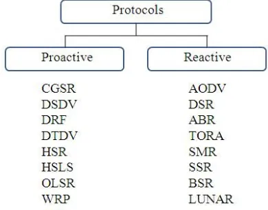
[image:1.612.327.522.415.568.2]Since the advent of Defense Advanced Research Projects Agency (DARPA) packet radio networks in the early 1970s, numerous protocols have been developed for ad hoc mobile networks. Such protocols must deal with the typical limitations of these networks, which include high power consumption, low bandwidth, and high error rates. These routing protocols may generally be categorized as:
Figure 1. Classification of Ad hoc routing protocols
Proactive Routing Protocols: Proactive routing protocols [2] attempt to maintain consistent, up-to-date routing information from each node to every other node in the network. These protocols require each node to maintain one or more tables to store routing information, and they respond to changes in network topology by propagating updates throughout the network in order to maintain a consistent network view. The areas in which they differ are the number of necessary routing-related tables and the methods by which changes in network structure are broadcast.
process within the network. This process is completed once a route is found or all possible route permutations have been examined. Once a route has been established, it is maintained by a route maintenance procedure until either the destination becomes in accessible along every path from the source or until the route is no longer desired.
Despite being designed for the same type of underlying network, the characteristics of each of these protocols are quite distinct.
A. Ad hoc on demand distance vector routing(AODV)
The Ad Hoc On-Demand Distance Vector (AODV) [7] routing protocol builds on the DSDV algorithm previously described. AODV is an improvement on DSDV because it typically minimizes the number of required broadcasts by creating routes on a demand basis, as opposed to maintaining a complete list of routes as in the DSDV algorithm. The authors of AODV classify it as a pure on-demand route acquisition system, since nodes that are not on a selected path do not maintain routing information or participate in routing table exchanges.
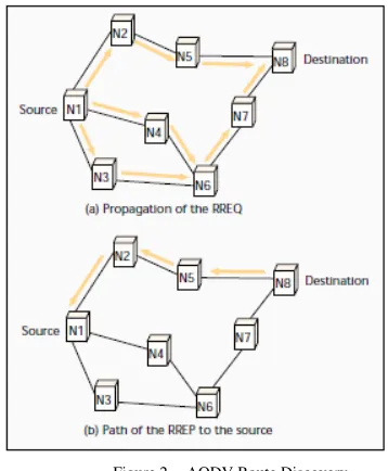
When a source node desires to send a message to some destination node and does not already have a valid route to that destination, it initiates a path discovery process to locate the other node. It broadcasts a route request (RREQ) packet to its neighbors, which then forward the request to their neighbors, and so on, until either the destination or an intermediate node with a “fresh enough” route to the destination is located. Figure 3a illustrates the propagation of the broadcast RREQs across the network. AODV utilizes destination sequence numbers to ensure all routes are loop-free and contain the most recent route information. Each node maintains its own sequence number, as well as a broadcast ID [3]. The broadcast ID is incremented for every RREQ the node initiates, and together with the node’s IP address, uniquely identifies an RREQ. Along with its own sequence number and the broadcast ID, the source node includes in the RREQ the most recent sequence number it has for the destination. Intermediate nodes can reply to the RREQ only if they have a route to the destination whose corresponding destination sequence number is greater than or equal to that contained in the RREQ.
During the process of forwarding the RREQ, intermediate nodes record in their route tables the address of the neighbor from which the first copy of the broadcast packet is received, thereby establishing a reverse path. If additional copies of the same RREQ are later received, these packets are discarded. Once the RREQ reaches the destination or an intermediate node with a fresh enough route, the destination/intermediate node responds by unicasting a route reply (RREP) packet back to the neighbor from which it first received the RREQ (Fig. 3b). As the RREP is routed back along the reverse path, nodes along this path set up forward route entries in their route tables which point to the node from which the RREP came. These forward route entries indicate the active forward route. Associated with each route entry is a route timer which will cause the deletion of the entry if it is not used within the specified lifetime. Because the RREP is forwarded along the path established by the RREQ, AODV only supports the use of symmetric links. Routes are maintained as follows. If a source node moves, it is able to reinitiate the route discovery protocol to find a new route to the destination.
If a node along the route moves, its upstream neighbor notices the move and propagates a link failure notification message (an RREP with infinite metric) to each of its active upstream neighbors to inform them of the erasure of that part of the route. These nodes in turn propagate the link failure notification to their upstream neighbors, and so on until the
[image:2.612.327.506.217.434.2]source node is reached. The source node may then choose to reinitiate route discovery for that destination if a route is still desired. An additional aspect of the protocol is the use of hello messages, periodic local broadcasts by a node to inform each mobile node of other nodes in its neighborhood. Hello messages can be used to maintain the local connectivity of a node. However, the use of hello messages is not required. Nodes listen for retransmission of data packets to ensure that the next hop is still within reach. If such a retransmission is not heard, the node may use any one of a number of techniques, including the reception of hello messages, to determine whether the next hop is within communication range. The hello messages may list the other nodes from which a mobile has heard, thereby yielding greater knowledge of network connectivity.
Figure 2. AODV Route Discovery
B. Dynamic Source Routing (DSR)
The Dynamic Source Routing (DSR) [11] protocol presented in is an on-demand routing protocol that is based on the concept of source routing. Mobile nodes are required to maintain route caches that contain the source routes of which the mobile is aware. Entries in the route cache are continually updated as new routes are learned.
© 2010, IJARCS All Rights Reserved 582
[image:3.612.72.284.331.444.2]A route reply is generated when the route request reaches either the destination itself, or an intermediate node which contains in its route cache an unexpired route to the destination. By the time the packet reaches either the destination or such an intermediate node, it contains a route record yielding the sequence of hops taken. If the node generating the route reply is the destination, it places the route record contained in the route request into the route reply. If the responding node is an intermediate node, it will append its cached route to the route record and then generate the route reply. To return the route reply, the responding node must have a route to the initiator. If it has a route to the initiator in its route cache, it may use that route. Otherwise, if symmetric links are supported, the node may reverse the route in the route record. If symmetric links are not supported, the node may initiate its own route discovery and piggyback the route reply on the new route request. Route maintenance is accomplished through the use of route error packets and acknowledgments. Route error packets are generated at a node when the data link layer encounters a fatal transmission problem. When a route error packet is received, the hop in error is removed from the node’s route cache and all routes containing the hop are truncated at that point. In addition to route error messages, acknowledgments are used to verify the correct operation of the route links. Such acknowledgments include passive acknowledgments, where a mobile is able to hear the next hop forwarding the packet along the route.
Figure 3. Building of route record during route discovery
Figure 4. Propagation of route reply with the route record
III. MOBILITY MODELS
To evaluate the performance of a protocol for an ad hoc network, it is necessary to test the protocol under realistic conditions, especially including the movement of the mobile nodes. Since not many MANETs [4] have been deployed, most of this research is simulation based.
These simulations have several parameters including the mobility models and the communicating traffic pattern. MANET [6] protocol performance may vary drastically across
different mobility models. In the literature, there are a lot of models used, mostly in simulations. Among the common one is the Random Waypoint Model, which is a simple model that may be applicable to some scenarios. However, there are other mobility models that may be used to capture the more important mobility characteristics of scenarios that MANETs may develop.
A. Random Waypoint Mobility Model
A mobile node begins the simulation by waiting a specified pause time. After this time it selects a random destination in the area and a random speed distributed uniformly between 0 m/s and Vmax. After reaching its destination point, the mobile node waits again pause time seconds before choosing a new way point and speed. The mobile [8] nodes are initially distributed over the simulation area. This distribution is not representative to the final distribution caused by node movements. To ensure a random initial configuration for each simulation, it is necessary to discard a certain simulation time and to start registering simulation results after that time.
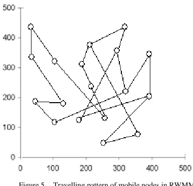
[image:3.612.328.518.403.586.2]The Random Waypoint Mobility Model is very widely used in simulation studies of MANET. As described in the performance measures in mobile ad hoc networks are affected by the mobility model used. One of the most important parameters in mobile ad hoc simulations is the nodal speed. The users want to adjust the average speed to be stabilized around a certain value and not to change over time. They also want to be able to compare the performance of the mobile ad -hoc routing protocols under different nodal speeds. For the Random Waypoint Mobility Model a common expectation is that the average is about half of the maximum, because the speeds in a Random Waypoint Model are chosen uniformly between 0 m/s and Vmax.
Figure 5. Travelling pattern of mobile nodes in RWMM
[image:3.612.61.269.471.593.2]approach the average speed stabilizes after a certain time at a value below 1/2 Vmax.
B. Reference Point Group Mobility Model (RPGMM)
In reference point group mobility model, simulate group behavior, where each node belongs to a group where every node follows a logical centre (group leader) that determines the group’s motion behavior. The nodes in a group are usually randomly distributed around the reference point. The different nodes use their own mobility model and are then added to the reference point which drives them in the direction of the group. At each instant, every node has a speed and direction that is derived by randomly deviating from that of the group leader. This general description of group mobility can be used to create a variety of models for different kinds of mobility applications. Group mobility as such can be used in military battlefield communications.
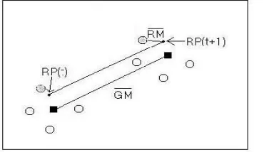
[image:4.612.326.521.197.346.2]In following figure, four MNs are initially placed in the lower left-hand corner of the simulation area. A black square is the group center; the circles near the group center are MNs in the group. One circle in figure is gray in order to distinguish it from the other MNs in the group. RPGM first calculates each MN’s reference point using the group motion vector GM that may be randomly chosen or predefined. The current reference point of the gray MN, t RP, moves towards the right hand corner of the simulation area alongside the group center. This location becomes the (new reference point, t RP +1), for the gray MN. Finally, the new position for the gray MN is calculated by summing a random motion vector, RM, with the new reference point. The length of RM is uniformly distributed within a specified radius centered at (t RP+1) and its direction is uniformly distributed between 0 and 2 . This process is repeated for each MN in the group. The RPGM model was designed to depict scenarios such as an avalanche rescue. During an avalanche rescue, the responding team consisting of human and canine members work cooperatively. The human guides tend to set a general path for the dogs to follow, since they usually know the approximate location of victims. The dogs each create their own “random” paths around the general area chosen by their human counterparts.
Figure 6. Travelling pattern of mobile nodes in RPGM
C. Manhattan Grid MobilityModel (MGMM)
The Manhattan mobility model is proposed to model movement in an urban area. In the Manhattan model, the mobile node is allowed to move along the horizontal or vertical streets on the urban map. At an intersection of a horizontal and a vertical street, the mobile node can turn left, right or go straight. The probability of moving on the same street is 0.5, the probability of turning left is 0.25 and the probability of turning right is 0.25. The velocity of a mobile node at a time
[image:4.612.61.246.508.615.2]slot is dependent on its velocity at the previous time slot. Also, a node’s velocity is restricted by the velocity of the node preceding it on the same lane of the street. Manhattan mobility model focuses on nodes moving along horizontal or vertical streets, which is not enough to model nodes moving along non-horizontal and non-vertical streets. Moreover, Manhattan model is not suitable to model the movement happening in the intersections of highway systems, this is much more complex than the intersection of local streets. Thus, Manhattan mobility model is expected to have high spatial dependence and high temporal dependence. On top of that, it also imposes geographic restrictions on node mobility, though it gives flexibility for the nodes to change its direction.
Figure 7. Travelling pattern of mobile nodes in MGMM
D. Gauss Markov Mobility Model (GMMM)
In Gauss Markov Model [9], for each mobile node two separate values are maintained instead of one speed vector: The mobile's speed and its direction of movement. The default method of handling mobile nodes that move out of the simulation is that nodes may continue to walk beyond the area boundary, which causes the next movement vector update not to be based on the prior angle, but on an angle that brings the nodes back onto the field. Therefore, the field size is automatically adapted to the node movements after scenario generation. New speed and direction of movement are simply chosen from a normal distribution with a mean of the respective old. Speed values are constrained to a certain interval that can be specified If a newly chosen speed value is outside of this interval, it is changed to the closest value inside of the interval (which is either the minimum or the maximum value).
[image:4.612.315.501.570.718.2]© 2010, IJARCS All Rights Reserved 584
IV. THE TRAFFIC AND SCENARIO GENERATOR
Simulations have been carried out by Network Simulator 2.33. In this simulation we have used Continuous bit rate (CBR) traffic sources, The mobility models used are Random Waypoint, Reference Point Group, Gauss Markov, and Manhattan Grid in a 500 m x 500 m field, Average packet size is of 512 bytes.
V. PERFORMANCE METRICS
Packet Delivery ratio (PDR) - Packet delivery ratio is calculated by dividing the number of packets received by the destination through the number of packets originated by the CBR source.
VI. SIMULATION SETUP
[image:5.612.322.556.115.714.2]Numbers of nodes are kept constant on 100 nodes, Maximum node speed is varied from 5, 10, 15, 20 and 25, Packet size, i.e. Network load is varied from 4 to 16 packets / s, and Pause Time is kept constant at 10s. Simulation time is kept to 100 s for all scenarios. In this simulation we wanted to investigate how AODV and DSR behave related to packet size and mobility speed when they are varied in different Mobility models.
Table I. Simulation setup for varying parameters
Parameter Value
Simulation time 100 s
No. of Nodes 100
Pause time 10s
Environment Size 500 m x 500 m,
Traffic Type Constant Bit Rate
Maximum Speed 5, 10, 15, 20, 25 m/s.
Network load 4, 8, 12, 16 packets/s
Mobility Models
Random Waypoint Reference Point Group Gauss Markov Manhattan Grid
VII. RESULTS AND DISCUSSIONS
During the simulation we have increased the network load, mobility speed in each mobility model we implemented, and recorded the performance of both the protocols. We did this simulation for 100 secs with maximum 8 cbr connections. From the results it is evident that AODV and DSR are showing very comparative results in different scenarios.
VIII. PERFORMANCE EVALUATION
Results illustrate that the performance of a routing protocol varies widely across different mobility models and hence the study results from one model cannot be applied to other model. Hence we have to consider the mobility of an application while selecting a routing protocol. Our experimental results show the following results for different mobility models.
A. Performance for Manhattan Grid Mobility Model
Results and reading shows that, overall performance of AODV is better as compared to DSR in this scenario.
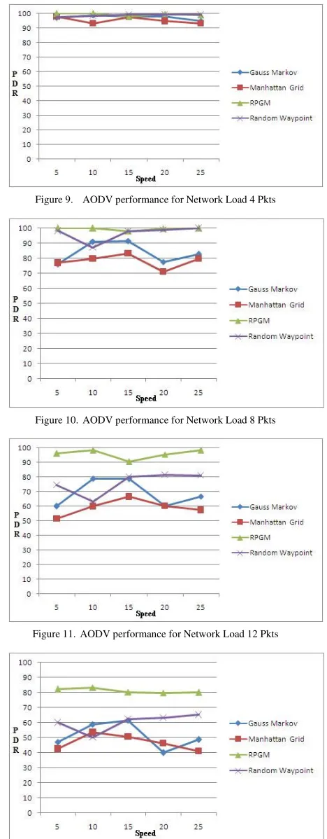
B. Performance for Reference Point Group Mobility Model
Both protocols are performing best for this mobility model delivering 95-100% packets (when network load is small) and for higher network load of 16 pkts / s, PDR is decreased to 73-85%.
Figure 9. AODV performance for Network Load 4 Pkts
Figure 10. AODV performance for Network Load 8 Pkts
Figure 11. AODV performance for Network Load 12 Pkts
[image:5.612.103.253.338.494.2]C. Performance for Gauss Markov Mobility Model
As compared to other mobility model, both protocols are showing less PDR but for higher network load it is better than Manhattan Grid.
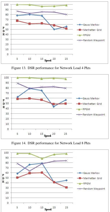
D. Performance for Random Waypoint Mobility Model
In this scenario, performance of both reactive routing protocols AODV and DSR is reduced when mobility speed and network load is increased.
Figure 13. DSR performance for Network Load 4 Pkts
Figure 14. DSR performance for Network Load 8 Pkts
Figure 15. DSR performance for Network Load 12 Pkts
Figure 16. DSR performance for Network Load 16 Pkts
IX. CONCLUSION AND FUTURE WORK
It is observed from our experimental result that for Manhattan Grid, AODV can be considered because it is performing well as compared to DSR. For, RPGM any protocol will be suitable because both are showing comparative result. For lower mobility and smaller network load, Random Waypoint can be considered and for lower mobility and smaller network load, either AODV or DSR should be used but for higher mobility and larger network load any one of AODV or DSR will be considerable, again because they are showing comparative result.
The future scope is improving the overall performance of AODV in various situations as compared to DSR. Further simulation needs to be carried out for the performance evaluation with not only increased mobility speed and network load, but also varying other related parameters like pause time, attraction point etc.
X. REFERENCES
List and number all bibliographical references in 9-point Times, single-spaced, at the end of your paper. When referenced in the text, enclose the citation number in square brackets, for example [1]. Where appropriate, include the name(s) of editors of referenced books. The template will number citations consecutively within brackets [1]. The sentence punctuation follows the bracket [2]. Refer simply to the reference number, as in [3]—do not use “Ref. [3]” or “reference [3]” except at the beginning of a sentence: “Reference [3] was the first . . .”
Number footnotes separately in superscripts. Place the actual footnote at the bottom of the column in which it was cited. Do not put footnotes in the reference list. Use letters for table footnotes.
Unless there are six authors or more give all authors’ names; do not use “et al.”. Papers that have not been published, even if they have been submitted for publication, should be cited as “unpublished” [4]. Papers that have been accepted for publication should be cited as “in press” [5]. Capitalize only the first word in a paper title, except for proper nouns and element symbols.
For papers published in translation journals, please give the English citation first, followed by the original foreign-language citation [6].
[image:6.612.326.555.53.189.2] [image:6.612.72.302.155.599.2]© 2010, IJARCS All Rights Reserved 586
[2] Elizabeth M. Royer, C.K. Toh, “A Review of Current Routing Protocols for Ad Hoc Mobile Wireless Networks”
[3] Aditya Goel, Ajaii Sharma , “Performance Analysis of Mobile Ad-hoc Network Using AODV Protocol”, International Journal of Computer Science and Security (IJCSS), Volume (3): Issue (5), Page No.334
[4] Yasser Kamal Hassan, Mohamed Hashim Abd El-Aziz, and Ahmed Safwat Abd El-Radi , “Performance Evaluation of Mobility Speed over MANET Routing Protocols”, International Journal of Network Security, Vol.11, No.3, PP.128{138, Nov. 2010, Page No.128 [5] Mamoun Hussein Mamoun, “Performance Comparison
of Mobile Ad-hoc Network Routing Protocol”, MCN 2007 Conference, November 7-10, 2007 , Page No.07 [6] A.Boomarani Malany, V.R.Sarma Dhulipala, and
RM.Chandrasekaran, “Throughput and Delay Comparison of MANET Routing Protocols”, Int. J. Open Problems Compt. Math., Vol. 2, No. 3, September 2009 , ISSN 1998-6262, Page No.461
[7] Ian D. Chakeres, Elizabeth M. Belding-Royer, “AODV Routing Protocol Implementation Design”,
[8] Stuart Kurkowski, Tracy Camp, Michael Colagrosso, “MANET Simulation Studies: The Incredibles”, Mobile Computing and Communications Review, Volume 1, Number 2, Page No.01
[9] Natarajan Meghanathan, “Impact of the Gauss-Markov Mobility Model on Network Connectivity, Lifetime and Hop Count of Routes for Mobile Ad hoc Networks”, JOURNAL OF NETWORKS, VOL. 5, NO. 5, MAY 2010, Page No.509
[10]Neeti Soni, “Exploiting the need of Comparative study of routing protocols and Misbehaving node in wireless network”, Published in International Journal of Advanced Engineering & Application, June 2010 Issue
[11]Anuj K. Gupta, Dr. Harsh Sadawarti, Dr. Anil K. Verma, “Performance analysis of AODV, DSR & TORA Routing Protocols”, IACSIT International Journal of Engineering and Technology, Vol.2, No.2, April 2010, ISSN: 1793-8236