Volume 4, No. 6, May 2013 (Special Issue)
International Journal of Advanced Research in Computer Science
REVIEW ARTICAL
Available Online at www.ijarcs.info
GSM mobile phone based LED scrolling message display system
Priyanka A. Borkar
B.E (Final Year) Information Technology Jawaharlal Darda Institute of Engineering & Technology,
Yavatmal, India [email protected]
Ashish K. Muley
B.E (Final Year) Information Technology
Jawaharlal Darda Institute of Engineering & Technology, Yavatmal, India
Niraj B.Masram
B.E (Final Year) Information Technology Jawaharlal Darda Institute of Engineering & Technology,
Yavatmal, India [email protected]
Dr. R.M. Tugnayat
H.O.D of Information Technology Jawaharlal Darda Institute of
Engineering & Technology, Yavatmal, India
Abstract: Wireless communication has announced its arrival on big stage and the world is going mobile. We want to control everything and without moving an inch. The use of “Embedded System in Communication” has given rise to many interesting applications that ensures comfort and safety to human life. One of such applications is public addressing system (PAS). In this technical paper explains how a reliable and an authentic wireless communication could be easily developed between a mobile phone and microcontroller using GSM (Global System for Mobile Communication) MODEM. It is proposed to implement this project at the institute level. It is proposed to place display boards in major access points. Now-a-days LED Message Scrolling Displays are becoming very popular. These displays are used in shopping malls, theaters, public transportation, traffic signs, highways signs, etc. This paper describes the GSM based LED display.
Keywords: GSM modem, LED display, transmitter, receiver.
I. INTRODUCTION
The led Display System is aimed at the colleges and universities for displaying day-to-day information continuously or at regular intervals during the working hours. Being GSM-based system, it offers flexibility to display flash news or announcements faster than the programmable system. GSM-based display system can also be used at other public places like schools, hospitals, railway stations, gardens etc. without affecting the surrounding environment. The led display system mainly consists of a GSM receiver and a display toolkit which can be programmed from an authorized mobile phone. It receives the SMS, validates the sending Mobile Identification Number (MIN) and displays the desired information after necessary code conversion. It can serve as an electronic notice board and display the important notices instantaneously thus avoiding the latency. Being wireless, the GSM based led display is easy to expand and allows the user to add more display units at anytime and at any location in the campus depending on the requirement of the institute.
Now-a-days LED Message Scrolling Displays are becoming very popular .These displays are used in shopping malls, theatres , public transportation, traffic signs, highways signs, etc., The big problem with these displays is to carry a computer or special keyboard for generating and sending messages to LED moving display boards dynamically. Carrying a host computer or special keyboard every time to generate message for LED display boards is big headache and also increase cost if it go for wireless based message sending.
To make the LED scrolling display more portable, a GSM mobile phone is used instead of carrying keyboard or a host computer for generating or sending messages to LED display board. A text message is typed in the GSM mobile phone and sent it by using SMS service of the mobile phone to LED moving display boards. A GSM modem is connected to the LED display hardware is used to receive the SMS and send it to the controller circuit of the LED display. Then the controller circuit of the LED display filters the message content in SMS and changes the display text in LED display dynamically. By using this SMS service it is possible to change the text in the LED display board from anywhere in the country. The idea implemented in this project reduces the total cost that is required in the traditional LED display boards not only it makes easier to send message to the LED display boards. The project uses a GSM modem at the display side to receive SMS. An IC 89C51RD2 belongs to microcontroller act as controller to drive the LED display board. Along with these a power supply unit and supporting hardware for microcontroller is used.
II. ANALYSISOFPROBLEM
cities, means he has to go there with laptop and change the message by connecting into PC .This system is also useful mainly for police or army .i.e. displays will be connected to all the main centers in city if they want to display messages about something crucial within 5 minute, which they cannot. But, we used this system in college for student and teacher convenience using this GSM based system HOD or T&P department display message about any notice. So keeping this in mind a new display system which can be accessed remotely, using the GSM technology to make the communication between microcontroller and mobile was designed.
III. DESIGNLAYOUT
In this paper, it is proposed to design a model where the message to be displayed is sent through a SMS from an authorized transmitter. The toolkit receives the SMS, validates the user and displays the desired information after necessary code conversion.
The main components of the Fig.1 contains microcontroller 89c51 RD2 which is interfaced with PC via MAX232level convertor. MAX 232 level converter is used to convert RS232 voltage to TTL voltage levels and vice versa.
[image:2.595.314.553.90.226.2]A 48x 6Character LED display is attached in byte mode to port 1 of microcontroller. This display will be used to display the messages /advertisements. Microcontroller coding will be done using Embedded C and Kiel. The microcontroller displays the message in the LCD display board. The microcontroller used in this case is AT89c51RD2.
Figure 1 Block diagram of system.
IV. HARDWAREREQUIREMENTS
The components of the Fig.1 block diagram are:
A. Power Supply:
a. Power Supply is an important part of a circuit. It provides required supply to different blocks of the circuit from input
b. The main blocks include transformer, rectifier circuit, filter circuit, and regulator circuit. Voltage regulator IC LM7805 is used as a voltage regulator.
Figure 2 Power Supply
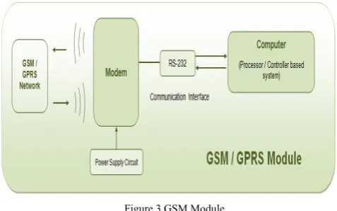
B. GSM Modem:
GSM/GPRS MODEM is a class of wireless MODEM devices that are designed for communication of a computer with the GSM and GPRS network. It requires a SIM (Subscriber Identity Module) card just like mobile phones to activate communication with the network. Also they have IMEI (International Mobile Equipment Identity) number similar to mobile phones for their identification. A GSM/GPRS MODEM can perform the following operations:
a. Receive, send or delete SMS messages in a SIM. b. Read, add, search phonebook entries of the SIM. c. Make, Receive, or reject a voice call.
[image:2.595.37.281.412.564.2]The MODEM needs AT commands, for interacting with processor or controller, which are communicated through serial communication. These commands are sent by the controller/processor. The MODEM sends back a result after it receives a command. Different AT commands supported by the MODEM can be sent by the processor/controller/computer to interact with the GSM and GPRS cellular network.
Figure 3 GSM Module
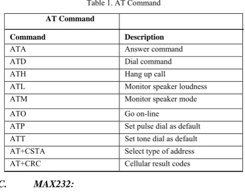
a. AT commands used by GSM:
AT commands are used to control MODEMs. AT is the abbreviation for Attention. These commands come from Hayes commands that were used by the Hayes smart modems. The Hayes commands started with AT to indicate the attention from the MODEM
Following are the types of AT command:
[image:2.595.314.553.455.604.2]b) Read command - used to get mobile phone or MODEM settings for an operation. Fig3:GSM Module SYNTAX: AT<command name>?
c) Set commands - used to modify mobile phone or MODEM settings for an operation. SYNTAX: AT<command name>=value1,value2,…, valueN Some values in set commands can be optional.
d) Execution commands - used to carry out an operation. SYNTAX: AT<command name>=parameter1, parameter2, …, parameterN
[image:3.595.37.276.230.418.2]Some of the AT command’s are as follows:
Table 1. AT Command
AT Command
Command Description
ATA Answer command
ATD Dial command
ATH Hang up call
ATL Monitor speaker loudness
ATM Monitor speaker mode
ATO Go on-line
ATP Set pulse dial as default
ATT Set tone dial as default
AT+CSTA Select type of address
AT+CRC Cellular result codes
C. MAX232:
The MAX232 is a dual driver/receiver that includes a capacitive voltage generator to supply EIA-232 voltage levels from a single 5-V supply. Each receiver converts EIA- 232 inputs to 5-V TTL/CMOS levels. Each driver converts TTL/CMOS input levels into EIA-232 levels.
a. FEATURE
b. Meets or Exceeds TIA/EIA-232-F and ITU Recommendation V.28.
c. Operates From a Single 5-V Power Supply With 1.0-_F Charge-Pump Capacitors
d. Operates Up To 120 kbit/s. e. Two Drivers and Two Receivers. f. 30-V Input Levels.
g. Low Supply Current . . . 8 mA Typical.
Figure 4 Pin Configurations MAX232
D. 89C51RD2 MICRO-CONTROLLER:
The 89C51RD2 device contains a non-volatile64kB Flash program memoryis both parallelprogrammable and serial In-System and In-Application Programmable. In-In-System Programming (ISP) allows the user to download new code while the microcontroller sits in the application. In-Application Programming (IAP) means that the microcontroller fetches new program code and reprograms itself while in the system. This allows for remote programming over a modem link. A default serial loader (boot loader) program in ROM allows serial In-System programming of the Flash memory via the UART withoutthe need for a loader in the Flash code. For In-Application Programming, the user program erases and reprograms the Flash memory by use of standard routines contained in ROM.
This device executes one machine cycle in 6 clock cycles, hence providing twice the speed of a conventional 80C51. An OTP configuration bit lets the user select conventional 12 clock timing if desired.
This device is a Single-Chip 8-Bit Microcontroller manufactured in advanced CMOS process and is a derivative of the 80C51 microcontroller family. The instruction set is 100% compatible with the 80C51 instruction set.
a. FEATURE
b. 80C51 Central Processing Unit.
c. On-chip Flash Program Memory with In-System Programming (ISP) and In-Application Programming (IAP) capability.
d. Boot ROM contains low level Flash programming routines for downloading via the UART.
e. Can be programmed by the end-user application (IAP).
f. Speed up to 20 MHz with 6 clock cycles per machine cycle(40 MHz equivalent performance) up to 33 MHz with 12 clocks per machine cycle.
g. RAM expandable externally to 64 Kb. h. 4 level priority interrupt.
i. 8 interrupt sources. j. Four 8-bit I/O ports.
E. 74HC595:
The 74HC595 are 8-stage serial shift registers with a storage register and3-state outputs. The registers have separate clocks. Data is shifted on the positive-going transitions of the shift register clock input (SHCP).The data in each register is transferred to the storage register on a positive-going transition of the storage register clock input (STCP). If both clocks are connected together, the shift register will always be one clock pulse ahead of the storage register.
a. FEATURE b. 8-bit serial input.
c. 8-bit serial or parallel output. d. Storage register with 3-state outputs. e. Shift register with direct clear. f. 100 MHz (typical) shift out frequency.
F. Led Matrix Display:
The MAX6953 is a compact cathode-row display driver that interfaces microprocessors to 7 ✕ 6 dot-matrix LED displays through an I2C™-compatible serial interface. The MAX6953 drives up to six digits (252 LEDs). Included on-chip are an ASCII 104-character font, multiplex scan circuitry, column and row drivers, and static
RAM that stores each digit, as well as font data for 24 user-definable characters. The segment current for the LEDs is set by an internal digit-by-digit digital brightness control.
a. FEATURE
b. 400kbps 2-Wire Interface Compatible with I2C c. 2.7V to 5.5V Operation
d. Drives 4 Monocolor or 2 Bicolor Cathode-Row 7 ✕ 6 Matrix Displays
e. Built-In ASCII 252-Character Font f. 24 User-Definable Characters Available g. Automatic Blinking Control for Each Segment h. 70μA Low-Power Shutdown (Data Retained) i. 16-Step Digital Brightness Control
j. Display Blanked on Power-Up
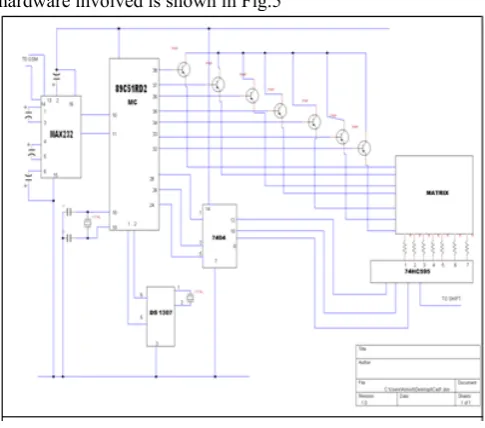
V. CIRCUITDIAGRAM
[image:4.595.36.279.376.590.2]The overall circuit diagram of the system including all the hardware involved is shown in Fig.5
Figure 5 Circuit Diagram
VI. SOFTWAREREQUIRED
A. Express PCB:
Express PCB is free PCB software and is a snap to learn and use. Designing circuit boards is simple for the beginner and efficient for the professional. In this project we used PCB for designing project required circuit diagram.
B. TinyCAD
We used TinyCAD to draw our own project diagram and give layout using the library provided by TinyCAD.
C. Embedded C:
Embedded C is used for microcontroller programming. There is a large and growing – international demand for programmers with 'embedded' skills, and many desktop developers are starting to move into this important area. Because most embedded projects have severe cost constraints, they tend to use low-cost processors like the 8051 family of devices considered in this paper.
D. Keil:
Development tools for the 8051 Microcontroller Architecture support every level of software developer from the professional applications engineer to the student just learning about embedded software development. The Keil 8051 Development Tools are designed to solve the complex problems facing embedded software developers.
VII. APPLICATION
A. Educational Institution and Organization:
Currently we rely on putting up papers on notice boards to inform people of events. This method can be discarded by using GSM based LED display to display information in real time. E.g. Placement news, cultural activities news, etc.
B. Advertisement:
In shopping malls we get to hear the offers on various products from time to time. Instead we continuously display the information regarding the products and related offers on electronic display boards.
C. Railway Station:
Instead of announcing the delay in arrival of trains we can display the information.
G. Hotels:
To display the availability of the rooms and the room rents the type of rooms.
D. Nursing homes:
To display the staff attendance, the availability of the doctors, the list of the specialized doctors, no of in patients etc.
VIII. MERITS
A. User friendly:
Messages are only to be typed on a mobile or a computer, which in turn are displayed wirelessly on the display unit.
B. Eliminates use of printers:
Since we don’t use papers to display information, printers are also of no use in this system.
C. Faster means of transferring information:
D. Future Enhancement:
a. A commercial model can be able to display more than one message at a time.
b. In our system we are sending messages via GSM network and displaying on a LED by utilizing AT commands. The same principle can be applied to control electrical appliances at a distant location. c. This technology could be further modified and more
upgraded as per individual need and interest. We have discussed some basic ideas of this technology. And depending on innovative applications user can upgrade as per requirement.
IX. CONCLUSION
Now a day’s every advertisement is going to be digital. The big shops and shopping centers are using the digital moving displays now. But using the GSM system we can make our communication more efficient and faster, with greater efficiency we can display the messages and with less errors and maintenance. This model can be used very efficiently in establishments like chain restaurants wherein the order and special discounts can be displayed at all branches simultaneously, in colleges wherein students and staffs can be informed simultaneously in no time. It can be set up at public transport places like railways, bus station, and airport and also at roadside for traffic control and in emergency situations, it is cost efficient system and very easy to handle. Latency involved in using of papers in displaying of notices is avoided and the information can be updated by the authorized persons.
X. REFERENCES
[1]. Gao, W., Zhang, G. and Jiang, X. “Study Implementation of Agricultural SMS Management System”. In Proceedings of IEEE International Conference on Information Technology and Computer Science, 13-17 October 2009, Beijing, China, pp. 1-4, 2009.
[2]. Shereen, N. Z. and Rozumah, B. “Mobile Phone use Amongst Student in University in Malaysia: It correlates and relationship to Psychological Health”. European Journal of Scientific Research. Vol. 37. No.2. pp. 206 – 218, 2009
[3]. Bollen, L., Eimler,S. and Hoppe, H.U. “SMS-based Discussions – Technology Enhanced Collaboration for a Literature Course”. In Proceedings of the 2nd IEEE International Workshop on Wireless and Mobile Technologies in Education, 24- 27 May 2004, Germany, pp. 1-2, 2004
[4]. Deng chunjjan, Liu Wei, Zou Kun, Yang Liang “A Solution Of LED Large Screen Display Based On Wireless Communication”,10.1109/apwcs.2010.24
[5]. Books: GSM and Personal Communicati - ons Handbook- SiegmundRedl - MatthiasWeber- MalcolmW. Oliphant
[6]. Books: Principles and Applications of GSM - Vijay Garg
[7]. Sedra and Smith, Microelectronic Circuits, fourth edition,
Oxford University Press, 1998
[8]. R.S. Sedha, 2002. A Text Book of Applied Electronics, S. Chand and Company Ltd., New Delhi