Design and Development of GSM based Multiple LED
Display Boards
Rahul Kamboj
Centre for Development of
Advanced Computing, Mohali
Preeti Abrol
Centre for Development of
Advanced Computing, Mohali
ABSTRACT
There are several places which require vital notice to be displayed like colleges, railway stations, share-market, restaurants, hospitals etc. Looking into the present trend of information transfer it is seen that vital notice take time to be displayed on the displaying boards. This latency is not anticipated in most of the cases and must be avoided. The advancement in the technologies related to wireless communication has led to the emergence of several engineering designs to aid the human requirements. This paper presents a combination of wireless technology with LED Display Boards formalized by designing and integrating the hardware and software with AT89S52 microcontroller, GSM module, LCD, moving LED display. The proposed design overcome the difficulties faced by previous moving text message display modules using wired entry via computer, keyboard or remote control entry (small distance). The message is sent through a cell-phone which is accepted by the GSM module SIM 300 (master). Number authentication is done by AT89S52 microcontroller and the stored numbers in EEPROM is compared with the incoming number. The message will be valid only after the incoming cell phone number is validated. Authentication result is displayed on LCD whether the number is matched or not matched and the message is finally displayed on moving LED (Light emitting diode) display. Further the same SMS is itself sent by GSM module (master) to Multiple LED Display Boards which are connected via different GSM modules (slaves). The incoming number and the message are stored in EEPROM so that no previous message is lost even after power failure.
Keywords
GSM module, LCD, EEPROM, Keypad &SMS.
1.
INTRODUCTION
Wireless communication has announced its arrival on big scale and the world is going mobile. We want to control everything without really moving and as quick as possible. This control of appliances is possible through Embedded Systems. The use of “Embedded System in Communication” has given rise to many interesting applications which ensure a comfortable and secure human life. GSM (Global system for mobile communication) network is among the most widely used wireless communication networks today for calling or SMS (Short message service).
This project aims at developing a system that will display the message received by the GSM module. Microcontroller will then control the system by doing verification and thus making it more secure than other display systems. This system is easy to use in day to day life by any-one and at any place (globally). This will overcome the difficulties of latency faced by the previous moving text message display modules using
wired entry via computer, keyboard or remote control entry (small distance). Additionally it also have further more features as compare to earlier used wireless moving displays. This system consists of keypad through which numbers can be saved in EEPROM. The numbers which are stored in the EEPROM only that can display message on the LED display. So, there is no need to write any code after the SMS. EEPROM is available for saving incoming messages so that no previous message is lost even after power failure instead of using on chip memory of controller which is used in previous work. The numbers in EEPROM can only be stored after password authentication so, this system also provides security. LCD is available for displaying authentication results and displaying numbers which are stored in EEPROM. Whole circuit is connected with battery backup so system will work if there is no power.
In this project, system is built upon a GSM module SIM300 and a Microcontroller AT89S52, allowing users to display real-time messages. Microcontroller uses AT commands to monitor SIM300 module which receives incoming messages, manipulates them and takes appropriate actions.
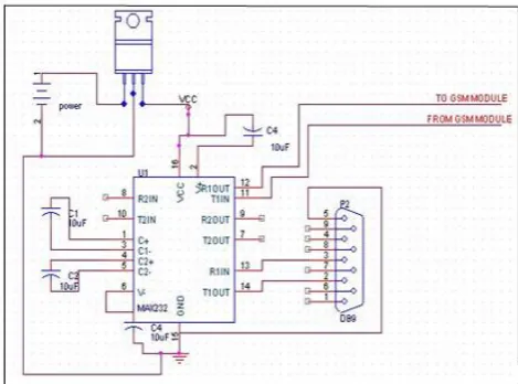
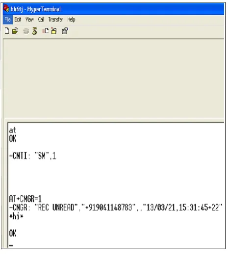
[image:1.595.316.551.500.674.2]Firstly, a circuit is designed in order to connect GSM module to PC through MAX-232 circuit and a communication link was created via HYPERTERMINAL as shown in Figure 1. and Figure 2. respectively.
Figure 2: Communication link via hyper terminal
2.
RELATED WORKS
Currently, the moving text message display modules are using wired entry via computer, keyboard or remote control. This paper presents an experiment to give a start to the era of real-time noticing. This paper discusses about writing the message which is to be displayed in mobile and send it as SMS to other side. This received message is fetched into Microcontroller and after authentication it is displayed on LCD screen. Also by interfacing a voice data recording IC with Microcontroller announcements in real-time could also be done [1].
This project, focused on application of LED in graphic displays. Main target of designed and manufactured system was its versatility. It was obtained by projecting similar segments that one can merge at will. A simple clock with one segment or sophisticated display for advertisements has been built.LED matrices have driven by 8-bit shift registers, which are controlled by AVR micro-controllers. Micro-controller application allows connecting extension modules such as digital thermometer, easily. Communication between micro-controller and personal computer is over RS232 interface. This provides possibility to drive display over TCP/IP protocol [2].
The prototype of the GSM based display toolkit was efficiently designed. This prototype has facilities to be integrated with a display board thus making it truly mobile. The toolkit accepts the SMS, stores it, validates it and then displays it in the LCD module. The SMS is deleted from the SIM each time it is read, thus making room for the next SMS. The major constraints incorporated are the use of „*‟ as the termination character of the SMS and the display of one SMS as a time. These limitations can be removed by the use of higher end microcontrollers and extended RAM [3].
This paper discusses a design of moving message LCD display system (MMDS) via short message service (SMS)
and LCD module in order to create MMDS. This system receives message through Short Message Service (SMS). It will check the authorization of the phone number and the microcontroller will convert the message that will be displayed into LCD format [4].
This paper describes a condition based reporting system of Power plant components using GSM technology. In this present approach, a dedicated microcontroller based hardware unit (DHU) has been developed to continuously measure the parameters of the viz. voltage, current, speed of turbine, frequency of generation etc. of the alternator to monitor the running condition of it also. Other than the generator there are subsystems which also need continuous monitoring. In this monitoring system each equipment is connected with one such DHU which is also connected to a Global System for Mobile Communication (GSM) modem. The preliminary level of fault or abnormality in operation of each component is diagnosed by the respective DHU and the fault or abnormalities details are reported to the pre-assigned operator through an SMS service. In extreme case, the provision of equipment shut down by a return SMS is also provided. A proto-type laboratory model has been set up and is working satisfactorily [5].
3.
BLOCK DIAGRAM
SMS from GSM module (master) and finally displays that SMS on different/Multiple LED display Board. In this way
one and the same SMS is displayed on multiple Display Boards.
Transmitter-:
Receiver:
Figure3: Block diagram showing different components
Cell-Phone
Microcontroll
er
AT89S52
GSM
module
(master)
MAX
232
LED
display
Buzzer
5V Power
supply
Keypad
EEPROM
LCD
5V
Power
supply
7805
Voltage
Regulator
12V
Power
supply
Microcontroller
AT89S52
GSM
module
(
SLAVE)
MAX
232
Figure4: Different AT commands used for GSM module
4.
GSM BASED MOVING LED DISPLAY METHODOLOGY
YES
NO
NO
YES
NO
YES
STARTCHECK OK/SAVE KEY IS PRESSED ON KEYPAD
SAVE/EDIT NUMBERS IN EEPROM TO WHICH SMS IS SENT BY GSM MODULE (MASTER) TO MULTIPLE
DISPLAYS
RESET
PASSWORD MATCHED ENTER PASSWORD
SAVE/EDIT NUMBERS IN EEPROM FROM WHICH GSM
MODULE RECEIVE SMS SHOW SIGNAL STRENGTH
MENU KEY IS PRESSED
NO
YES
YES
NO
Figure5: Software flow graph CHECK FOR SMS
GSM MODULE RECEIVES SMS
MICROCONTROLLER SAVES SMS & NUMBER
MICROCONTROLLER COMPARE NUMBER FROM WHICH SMS IS
RECIEVED
SAVE SMS IN EEPROM
SHOW SMS ON MOVING LED
DISLPLAY
SMS SEND TO NUMBERS SAVED IN EEPROM/ MULTIPLE DISPLAYS BY
MASTER GSM MODULE CHECK SMS
WITH CODE*#1#*
OR OTHER
SEND PREVIOUS SMS STORED IN EEPROM
UNMATCHED DISPLAY ON
LCD
MATCHED DISPLAY ON LCD
Figure 5 shows the Software Methodology of GSM Based Moving LED Display. Firstly, the software checks for whether OK/SAVE key is pressed on keypad. If OK/SAVE is pressed it goes into the subroutine where the numbers can be saved or edited through keypad in EEPROM to which GSM module sends SMS. If OK/SAVE is not pressed signal strength is displayed on LCD. After this it checks whether MENU key is pressed or not on keypad. If it is pressed then software goes in the subroutine of password matching. If it is not pressed then it keeps on showing signal strength. If password is found matched then the numbers can be saved or edited through keypad in EEPROM from which GSM module receives SMS. If password does not matches buzzer beeps three times and again shows signal strength on LCD. GSM module always checks for incoming SMS. On receiving an SMS, firstly microcontroller saves SMS and number from which SMS is received. Then it compares this number with the numbers stored in EEPROM. If number matches, „Matched‟ is displayed on LCD if not then „Not matched‟ is displayed on LCD. After matching the numbers, microcontroller checks for the code “*#1#*”. If it is there in SMS, it displays previous SMS which is stored in EEPROM on Moving LED Display. If SMS is other then this code then that SMS gets stored in EEPROM and is displayed on Moving LED Display. Finally, this received SMS is forwarded to numbers stored in EEPROM by GSM module.
NOTE- The major constraints incorporated are the use of „*‟ as the beginning and termination character of the SMS.
5.
RESULTS AND DISCUSSION
Firstly, the program will initialize by checking SAVE/OK key is pressed or not. If it is pressed program will go in subroutine of saving or editing numbers in EEPROM to which GSM module sends SMS as shown in Figure 6
Figure6: Stored numbers in EEPROM to which SMS is sent by GSM
If SAVE/OK key is not pressed then signal strength is displayed on LCD as shown in Figure 7.
Figure7: Signal strength displayed on LCD
Then software checks for MENU key on keypad. If it is pressed then software asks for password as shown in Figure 8.
Figure8: Password authentication before saving/editing
If password matches then the numbers from which GSM module receives SMS can be saved or edited as shown in Figure 9.
Figure9: Editing/saving numbers on LCD from which SMS is received by GSM module
When GSM module receives an SMS with „*‟ at the beginning and at the termination of an SMS from the valid number which is stored in EEPROM as shown in Figure 10. „Matched‟ get display on the LCD as shown in Figure 11. otherwise „Not matched‟ get displayed on LCD if an SMS is from invalid number which is not stored in GSM module as shown in Figure 12.
Figure10: SMS (*C-DAC*) send to SIM present in GSM module by the stored number
Figure11: Matched gets displayed on LCD if number is valid
Figure12: Not matched gets displayed on LCD if number is invalid
46
6.
CONCLUSION
[image:7.595.311.548.69.197.2]This project has facilities to integrate GSM module with a moving LED display board thus making it really wireless. This system accepts the SMS, stores it, validates it and then displays it on the moving LED display module. The validation depends upon the stored numbers in EEPROM which are compared with the incoming number. The numbers stored in EEPROM can be edited by keypad provided separately. The stored numbers are displayed on LCD. The key constraints included are the use of „*‟ as the beginning and termination of the SMS. Multiple moving LED displays are connected via different GSM modules at different geographical positions so that one and the same SMS will be displayed on all moving LED displays. Nonetheless, there are still new ideas to improve it and to add new functionality to it. Multiple moving LED display boards can be connected via ZigBee wireless network to display same message on different moving LED displays. Moving LED display can also be used to display SMS in more than one language as future enhancement.
Table 1. Comparison with previous work
S.N
O
Features
Previous
Work
Present Work
1.
Cost
Rs 12000.
Rs 7000.
2.
Keypad
Not available. Available for
saving
the
numbers
in
EEPROM.
3.
EEPRO
M
Not available. Available for
saving
numbers and
incoming
SMS.
4.
Security
No password
authenticatio
n is done.
Password
authenticatio
n
before
saving
numbers
in
EEPROM.
5.
LCD
Not available. Available for
displaying
authenticatio
n results and
displaying
numbers
which
are
stored
in
EEPROM.
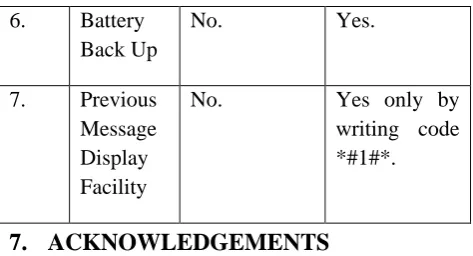
6.
Battery
Back Up
No.
Yes.
7.
Previous
Message
Display
Facility
No.
Yes only by
writing code
*#1#*.
7.
ACKNOWLEDGEMENTS
We would like to extend a special thank to C-DAC Mohali for providing us means to carry out our research work in precious way. We are also grateful to MHRD, Govt of India for providing us a platform to do our research work.
8.
REFERENCES
[1] Darshankumar C. Dalwadi, Ninad Trivedi, Amit Kasundra, “WIRELESS NOTICE BOARD Our Real-Time Solution” National Conference on Recent Trends in Engineering & Technology, May13-14 (2011) [2] Swiatkowski, M.; Wozniak, K.; Olczyk, L., "Student
Notice Board Based on LED Matrix System Controlled over TCP/IP Protocol," Photonics and Microsystems, 2006 International Students and Young Scientists Workshop, vol., no., pp.59,60, June 30 2006-July 2 2006 [3] Rohan Mishra, Sambit Kumar Das, “GSM BASED
DISPLAY LCD TOOLKIT” Department of Electronics and Communication Engineering National Institute of Technology Rourkela 2007.
[4] Badri, M.A.; Halim, A.K., "Design of moving massage LCD display system (MMDS) via Short Message Service (SMS) entry using Rabbit 2000 microcontroller," RF and Microwave Conference, 2008. RFM 2008. IEEE International, vol., no., pp.81, 85, 2-4 Dec. 2008. [5] Datta, J.; Datta, S.; Chowdhuri, S.; Bera, J., "GSM based
condition reporting system for power station equipments," Emerging Applications of Information Technology (EAIT), 2012 Third International Conference on , vol., no., pp.256,259, Nov. 30 2012-Dec. 1 2012. [6] Chen Peijiang; Jiang Xuehua, "Design and
Implementation of Remote Monitoring System Based on GSM," Computational Intelligence and Industrial Application, 2008. PACIIA '08. Pacific-Asia Workshop on, vol.1, no., pp.678, 681, 19-20 Dec. 2008.
[7] Xu Yang; Lei Zhang; Jiasheng Sun, "The control system for smart home based on GSM and the radio," Computer, Mechatronics, Control and Electronic Engineering (CMCE), 2010 International Conference on, vol.6, no., pp.134, 137, 24-26 Aug. 2010.
[8] Sehgal, V.K.; Singhal, M.; Mangla, B.; Singh, S.; Kulshrestha, S., "An Embedded Interface for GSM Based Car Security System," Computational Intelligence, Communication Systems and Networks (CICSyN), 2012 Fourth International Conference on , vol., no., pp.9,13, 24-26 July 2012
[9] Guifen Gu; Guili Peng, "The survey of GSM wireless communication system," Computer and Information Application (ICCIA), 2010 International Conference on , vol., no., pp.121,124, 3-5 Dec. 2010