ISSN (Print) : 2320 – 3765 ISSN (Online): 2278 – 8875
I
nternational
J
ournal of
A
dvanced
R
esearch in
E
lectrical,
E
lectronics and
I
nstrumentation
E
ngineering
(A High Impact Factor, Monthly, Peer Reviewed Journal)
Website: www.ijareeie.com Vol. 8, Issue 3, March 2019
Speed Control of BLDC Motor Using CUK
Converter
S. Swapna1, K.Siddappa Naidu2
Research Scholar, Department of Electrical and Electronics Engineering, Vel Tech Rangarajan Dr. Sangunthala R&D Institute of Science & Technology, Chennai, Tamil Nadu, India1
Asst. Professor, Department of Electrical and Electronics Engineering, GRT Institute of Engineering & Technilogy, Tiruttani, Tamil Nadu, India1
Professor , Department of Electronics and Communication Engineering, Vel Tech Rangarajan Dr. Sangunthala R&D Institute of Science & Technology, Chennai, Tamil Nadu, India2
ABSTRACT: The BLDCM are widely used in the low power application of servo motor due to their different advantages over conventional DC motors, induction motor and permanent magnet motor. However high performance motor require fast and accurate speed control of the system, quick revival of speed from any disturbance and sensitivity to motor parameter variation. To operate the motor with proper reference speed different controllers are widely used in industrial application. In this present work, a Cuk converter is designed with adaptive neuro based fuzzy PID controller is used to tune the PID controller parameters for speed control of BLDC motor. Ziegler- Nicholas tuning formula is used for tuning and gain predication of adaptive neuro fuzzy controller. Genetic algorithm is a strong optimization technique based on natural selection by considering the different parameters such as rise time settling time and overshoot of the response. Simulation results are obtained from different conventional controllers as well fuzzy-PID controller are compared with the adaptive neuro fuzzy PID controllers.
KEYWORDS: BLDCM, CUK Converter, Adaptive Neuro Fuzzy Interface System-PID(ANFIS-PID).
I. INTRODUCTION
RUSHLESS DC (BLDC) motors are recommended for many low and medium power drives applications because of their high efficiency, high flux density per unit volume,
low maintenance requirement, low EMI problems, high ruggedness and a wide range of speed control [1, 2]. Due to these advantages, they find applications in numerous areas
such as household application [3], transportation (hybrid vehicle) [4], aerospace [5], heating, ventilation and air conditioning (HVAC) [6], motion control and robotics [7],
renewable energy applications [8, 9] etc. The BLDC motor is a three phase synchronous motor consisting of a stator having a three phase concentrated windings and a rotor having permanent magnets [10, 11]. It doesn’t have mechanical brushes and commutator assembly, hence wear and tear of the brushes and sparking issues as in case of conventional DC machines are eliminated in BLDC motor and thus has low EMI problems. This motor is also referred as electronically commutated motor (ECM) since an electronic commutation based on the Hall-Effect rotor position signals is used rather than a mechanical commutation [12, 13].
II. SYSTEM CONFIGURATION
ISSN (Print) : 2320 – 3765 ISSN (Online): 2278 – 8875
I
nternational
J
ournal of
A
dvanced
R
esearch in
E
lectrical,
E
lectronics and
I
nstrumentation
E
ngineering
(A High Impact Factor, Monthly, Peer Reviewed Journal)
Website: www.ijareeie.com Vol. 8, Issue 3, March 2019
for its low frequency operation. BLDC motor is commutated electronically to operate the IGBT’s of VSI in fundamental frequency switching mode to reduce its switching losses. The PFC Cuk converter operating in CCM using a current multiplier approach is shown in Fig. 1; i.e. the current flowing in the input and output inductors (Li and Lo), and the voltage across the intermediate capacitor (C1) remain continuous in a switching period. Whereas, Fig. 2 shows a Cuk converter fed BLDC motor drive operating in DCM using a voltage follower approach. The current flowing in either of the input or output inductor (Li and Lo) or the voltage across the intermediate capacitor (C1) become discontinuous in a switching period [18, 19] for a PFC Cuk converter operating in DCM. A Cuk onverter is designed to operate in all three discontinuous conduction modes and a continuous conduction mode of operation and its performance is evaluated for a wide voltage control with unity power factor at AC mains.
Conventional schemes of PFC converters fed BLDC motor drive utilize an approach of constant DC link voltage of the VSI and controlling the speed by controlling the duty ratio of high frequency pulse width modulation (PWM) signals [22- 25]. The losses of VSI in such type of configuration are considerable since switching losses
depend on the square of switching frequency (Psw_loss α fS2). Ozturk et. al. [22] have proposed a boost PFC converter
based direct torque controlled (DTC) BLDC motor drive. They have the disadvantages of
using a complex control which requires large amount of sensors and higher end digital signal processor (DSP) for attaining a DTC operation with PFC at AC mains.
A. Control of BLDC Motor: Electronic Commutation
The conduction states of two switches (S1 and S4) are shown in Fig. 2. A line current iab is drawn from the
direct current link capacitor whose magnitude depends on the applied direct current link voltage (Vdc), back electromotive forces (ean and ebn), stator resistances (Ra and Rb), and self-inductance and mutual inductance (La, Lb,
ISSN (Print) : 2320 – 3765 ISSN (Online): 2278 – 8875
I
nternational
J
ournal of
A
dvanced
R
esearch in
E
lectrical,
E
lectronics and
I
nstrumentation
E
ngineering
(A High Impact Factor, Monthly, Peer Reviewed Journal)
Website: www.ijareeie.com Vol. 8, Issue 3, March 2019
Fig. 2. Operation of a Voltage Source Inverter -fed BLDC motor when switches S1 and S4 are conducting
III. SPEED CONTROL OF BLDC MOTOR
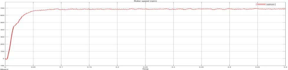
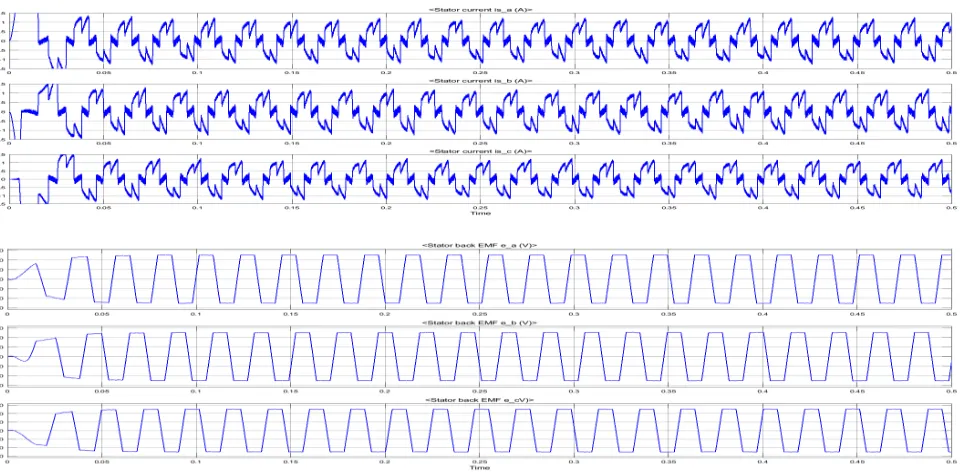
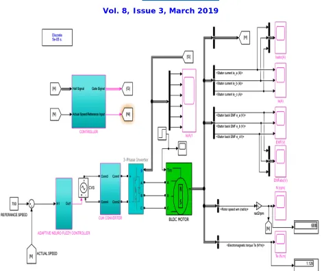
The performance characteristics of BLDC motor drive with conventional controller as well as combination of intelligent controllers have been investigated such as fuzzy PID[21].Figure 3-5 shows the simulation diagram cuk converter using adaptive neuro fuzzy PID controller. Table II shows the analysis of four different load configurations of the BLDC motor drive. The evaluation is based on settling time, rise time and peak overshoot of closed loop ANFIS PID controller implemented in BLDC motor drive.
TABLE I
SPECIFICATIONS OF BLDC MOTOR
PARAMETERS RATINGS
Voltage in volts 24 V
Current in Amps 8.5A
Power in Watts 250W
Speed in rpm 300
Resistance in ohms 0.2Ω
Rated Torque (Trated) 2.3 N.m
Number of Poles 3
Phase Inductance in Hentry 0.3mH
ISSN (Print) : 2320 – 3765 ISSN (Online): 2278 – 8875
I
nternational
J
ournal of
A
dvanced
R
esearch in
E
lectrical,
E
lectronics and
I
nstrumentation
E
ngineering
(A High Impact Factor, Monthly, Peer Reviewed Journal)
Website: www.ijareeie.com Vol. 8, Issue 3, March 2019
Fig. 3 (a) & (b) Speed & Torque Characteristics of BLDCM using converter
ISSN (Print) : 2320 – 3765 ISSN (Online): 2278 – 8875
I
nternational
J
ournal of
A
dvanced
R
esearch in
E
lectrical,
E
lectronics and
I
nstrumentation
E
ngineering
(A High Impact Factor, Monthly, Peer Reviewed Journal)
Website: www.ijareeie.com Vol. 8, Issue 3, March 2019
Fig 5 (a) & (b) Overall simulation diagram of BLDCM using Cuk converter
Table II. Performance parameters values with designed ANFIS PID controller using cuk converter
Different Load
Actual Speed (rpm)
Torque (Nm)
Time Period(sec)
Rising Time(sec) Settling Time(sec) Overshoot Error Speed (rpm)
No Load 700 0.1211 1 sec 31.791ms(0.031791s) 6.999ms(0.06791s) 0.681% 0 50% of
Load 700 1.484 1 sec
30.025ms(0.03025s) 6.074ms(0.006074s) 0.735%
0
75% of
Load 700 1.476 1 sec 0
Full Load
ISSN (Print) : 2320 – 3765 ISSN (Online): 2278 – 8875
I
nternational
J
ournal of
A
dvanced
R
esearch in
E
lectrical,
E
lectronics and
I
nstrumentation
E
ngineering
(A High Impact Factor, Monthly, Peer Reviewed Journal)
Website: www.ijareeie.com Vol. 8, Issue 3, March 2019
IV. CONCLUSION
A Cuk converter for Voltage Source Inverter fed BLDC motor drive has been designed for controlling the low speed of motor using adaptive nuero fuzzy PID controller achieving a low rise time, settling and peak overshoot time for the development of low cost BLDC motor for numerous low power equipments such fans, blowers, water pumps etc. The speed of the motor drive has been controlled by varying the DC link voltage of VSI; which allows the voltage source inverter to operate in fundamental frequency switching mode for reduced switching losses.
REFERENCES
[1] J. F. Gieras and M. Wing, Permanent Magnet Motor Technology- Design and Application, Marcel Dekker Inc., New York, 2002. [2] C. L. Xia, Permanent Magnet Brushless DC Motor Drives and Controls, Wiley Press, Beijing, 2012.
[3] Y. Chen, Y, C. Chiu, C, Y. Jhang, Z. Tang and R. Liang, “A Driver for the Single-Phase Brushless DC Fan Motor with Hybrid Winding Structure,” IEEE Trans. Ind. Electron., Early Access, 2012.
[4] S. Nikam, V. Rallabandi and B. Fernandes, “A high torque density permanent magnet free motor for in-wheel electric vehicle application,” IEEE Trans. Ind. Appl., Early Access, 2012.
[5] X. Huang, A. Goodman, C. Gerada, Y. Fang and Q. Lu, “A Single Sided Matrix Converter Drive for a Brushless DC Motor in Aerospace Applications,” IEEE Trans. Ind. Electron., vol.59, no.9, pp.3542-3552, Sept. 2012.
[6] W. Cui, Y. Gong and M. H. Xu, “A Permanent Magnet Brushless DC Motor With Bifilar Winding for Automotive Engine Cooling Application,” IEEE Trans. Magnetics, vol.48, no.11, pp.3348-3351, Nov. 2012.
[7] C. C. Hwang, P. L. Li, C. T. Liu and C. Chen, C, “Design and analysis of a brushless DC motor for applications in robotics,” IET Elect. Pow. ppl.,vol.6,no.7,pp.385-389,August 2012.
[8] T. K. A. Brekken, H. M. Hapke, C. Stillinger and J. Prudell, “Machines and Drives Comparison for Low-Power Renewable Energy and Oscillating Applications,” IEEE Trans. Energy Convers., vol.25, no.4, pp.1162-1170, Dec. 2010.
[9] N. Milivojevic, M. Krishnamurthy, A. Emadi and I. Stamenkovic “Theory and Implementation of a Simple Digital Control Strategy for Brushless DC Generators," IEEE Trans. Power Electron., vol.26, no.11, pp.3345-3356, Nov. 2011
[10] T. Kenjo and S. Nagamori, Permanent Magnet Brushless DC Motors, Clarendon Press, Oxford, 1985.
[11] J. R. Handershot and T.J.E Miller, Design of Brushless Permanent Magnet Motors, Clarendon Press, Oxford, 2010. [12] T. J. Sokira and W. Jaffe, Brushless DC Motors: Electronic Commutation and Control, Tab Books, USA, 1989. [13] H. A. Toliyat and S. Campbell, DSP-based lectromechanical Motion Control, CRC Press, New York, 2004.
[14] A. Ionovici, “A new computer-aided approach to the analysis of Cuk converter by using the alternator equations,” IEEE Trans. Power Electron., vol.4, no.3, pp.319-330, Jul 1989.
[15] S. C. Wong and Y. S. Lee, “SPICE modeling and simulation of hysteretic current-controlled Cuk converter,” IEEE Trans. Power Electron., vol.8, no.4, pp.580-587, Oct 1993.
[16] K. M. Smedley and S. Cuk, “Dynamics of one-cycle controlled Cuk converters,” IEEE Trans. Power Electron., vol. 10, no.6, pp.634-639, Nov 1995.
[17] L. Malesani, R. G. Spiazzi and P. Tenti, “Performance optimization of Cuk converters by sliding-mode control,” IEEE Trans. Power Electron., vol.10, no.3, pp.302-309, May 1995.
[18] Z. Chen, “PI and Sliding Mode Control of a Cuk Converter,” IEEE Trans. Power Electron., vol.27, no.8, pp.3695-3703, Aug. 2012
[19] M. Brkovic and S. Cuk, “Input current shaper using Cuk converter,” 14th Int. Telecomm. Energy Conf. (INTELEC), pp.532-539, 4-8 Oct 1992. [20] D. S. L. Simonetti, J. Sebastian and J. Uceda, “The Discontinuous Conduction Mode Sepic and Cuk Power Factor Preregulators: Analysis and Design”, IEEE Trans. Ind. Electron., vol. 44, no. 5, October 1997.
[21] P. Pillay and R. Krishnan,"Modeling simulation and analysis of a permanent magnet brushless dc motor drive," presented at the IEEE IAS Annual Meeting, Atlanta, 1987.
[22] Md Mustafa kamal , Dr.(Mrs.)Lini Mathew and Dr. S. Chatterji “Speed Control of Brushless DC Motor Using Fuzzy Based Controllers” 2014 IEEE Students’ Conference on Electrical, Electronics and Computer Science.
[23] S. B. Ozturk, Oh Yang and H. A. Toliyat, “Power Factor Correction of Direct Torque Controlled Brushless DC Motor Drive,” 42nd IEEE IAS Annual Meeting, pp.297-304, 23-27 Sept. 2007.
[24] T. Y. Ho, M. S. Chen, L. H. Yang and W. L. Lin, “The Design of a High Power Factor Brushless DC Motor Drive,” 2012 Int. Symposium on Computer, Consumer and Control (IS3C), pp.345-348, 4-6 June 2012.
[25] C. H. Wu and Y. Y. Tzou, “Digital control strategy for efficiency optimization of a BLDC motor driver with VOPFC,” IEEE Energy Conversion Congress and Exposition, (ECCE 2009), pp.2528-2534, 20- 24 Sept. 2009.