CNC Drawing Robot Using Arduino
Kharole Vitthal. P.1, Kadam Vishal. B.2, Shelke Satyjeet. G.3 Bukey Chetan. M.4 UG Student, Dept. of E&TC, STC Faculty of Engineering, Latur, Maharashtra, India1 UG Student, Dept. of E&TC, STC Faculty of Engineering, Latur, Maharashtra, India2 UG Student, Dept. of E&TC, STC Faculty of Engineering, Latur, Maharashtra, India3 Assistant Professor, Dept. of E&TC, STC Faculty of Engineering, Latur, Maharashtra, India4
ABSTRACT: The term “CNC” is a generic term which can be used to describe many types of device, this would include plotters, vinyl cutters, 3D printers, milling machines and others. CNC stands for Computer Numerically Controlled and basically means that the physical movements of the machine are controlled by instructions, such as co-ordinate positions that are generated using a computer. Digital image processing has become an functional as well as popular research area that goes from specialized photography to several different fields such as astronomy, meteorology, computer vision, medical imaging, among others. The main goal of digital image processing is to improve the pictorial information .The area of digital image processing refers to processing digital images by means of a digital computer .Numbers of edge detectors are developed each year
KEYWORDS: Stepper motor, Arduino, Linkspace.
I. INTRODUCTION
A CNC Drawing Robot is a special type of printer that uses a pen to draw letters on solid surfaces. In Computer Numeric Control (CNC), ARDUINO is used which is capable of processing logical instructions interfaced with a computer. The logical instructions are provided by using a computer in the form of code or text or image which is then transformed into a machine language by ARDUINO to be executed by the machine. A CNC plotter machine is a 3D controlled 2D plotting machines which uses a pen to draw text or image on any given solid surface. It can be used for the purposes such as PCB Design, logo design, etc. This project is based on CNC plotter machine. With the increasing demand for the use of CNC plotters in universities and laboratories, a cheap and less complex design is an absolute need. The parts used for the plotter in our project are easily available at a very low price and spare parts are also used.
CNC stands for Computer Numerically Controlled and basically means that the physical movements of the machine are controlled by instructions, such as co-ordinate positions that are generated using a computer. Digital image processing has become an functional as well as popular research area that goes from specialized photography to several different fields such as astronomy, computer vision, medical imaging, among others. The main goal of digital image processing is to improve the pictorial information .The area of digital image processing refers to processing digital images by means of a digital computer Effects such as refraction or poor focus can result in objects with boundaries defined by steady change in intensity. So, there are problems of false edge detection, missing true edges, edge localization, high computational time and problem due to noise. In order to significantly reduce the complexity of image processing algorithms, edge detection is used as the pre-processing step which helps in reducing the amount of data to be processed.
from specialized photography to several different fields such as astronomy, meteorology, computer vision, medical imaging, among others. The main goal of digital image processing is to improve the pictorial information .The area of digital image processing refers to processing digital images by means of a digital computer .Numbers of edge detectors are developed each year.
II. ARDUINO UNO REV 3
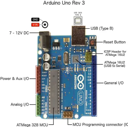
The Arduino UNO is an open-source microcontroller board based on the Microchip ATmega328P microcontroller and developed by Arduino.cc. The board is equipped with sets of digital and analog input/output (I/O) pins that may be interfaced to various expansion boards (shields) and other circuits. The board has 14 Digital pins, 6 Analog pins, and programmable with the Arduino IDE (Integrated Development Environment) via a type B USB cable. It can be powered by the USB cable or by an external 9-volt battery, though it accepts voltages between 7 and 20 volts. It is also similar to the Arduino Nano and Leonardo. The hardware reference design is distributed under a Creative Commons Attribution Share-Alike 2.5 license and is available on the Arduino website. Layout and production files for some versions of the hardware are also available.
The word "uno" means "one" in Italian and was chosen to mark the initial release of the Arduino Software. The Uno board is the first in a series of USB-based Arduino boards,and it and version 1.0 of the Arduino IDE were the reference versions of Arduino, now evolved to newer releases.The ATmega328 on the board comes preprogrammed with a bootloader that allows uploading new code to it without the use of an external hardware programmer. While the Uno communicates using the original STK500 protocol,it differs from all preceding boards in that it does not use the FTDI serial driver chip. Instead, it uses the Atmega16U2 (Atmega8U2 up to version R2) programmed as a USB-to-serial converter.
Figure 2.1: Arduino Uno Rev 3
2.1 GENERAL PIN FUNCTIONS
LED: There is a built-in LED driven by digital pin 13.pin is high value, the LED is on, when the pin is low, it's off.
VIN: The input voltage to the Arduino/Genuino board when it's using an external power source (as opposed to 5 volts from the USB connection or other regulated power source). You can supply voltage through this pin, or, if supplying voltage via the power jack, access it through this pin.
5V: This pin outputs a regulated 5V from the regulator on the board. The board can be supplied with power either from the DC power jack (7 - 20V), the USB connector (5V), or the VIN pin of the board (7-20V). Supplying voltage via the 5V or 3.3V pins bypasses the regulator, and can damage the board.
3V3: A 3.3 volt supply generated by the on-board regulator. Maximum current draw is 50 mA. GND: Ground pins.
IOREF: This pin on the Arduino board provides the voltage reference with which the microcontroller operates.
Reset: Typically used to add a reset button to shields which block the one on the board.
2.2 SPECIAL PIN FUNCTION
Each of the 14 digital pins and 6 analog pins on the Uno can be used as an input or output, using pinMode, digitalWrite, and digitalRead functions. They operate at 5 volts. Each pin can provide or receive 20 mA as recommended operating condition and has an internal pull-up resistor (disconnected by default) of 20-50k ohm. A maximum of 40mA is the value that must not be exceeded on any I/O pin to avoid permanent damage to the microcontroller. The Uno has 6 analog inputs, labeled A0 through A5, each of which provide 10 bits of resolution (i.e. 1024 different values). By default they measure from ground to 5 volts, though is it possible to change the upper end of their range using the AREF pin and the analogReference function.
In addition, some pins have specialized functions:
Serial / UART: pins 0 (RX) and 1 (TX). Used to receive (RX) and transmit (TX) TTL serial data. These pins are connected to the corresponding pins of the ATmega8U2 USB-to-TTL serial chip.
External interrupts: pins 2 and 3. These pins can be configured to trigger an interrupt on a low value, a rising or falling edge, or a change in value.
PWM (pulse-width modulation): 3, 5, 6, 9, 10, and 11. Can provide 8-bit PWM output with the analogWrite() SPI (Serial Peripheral Interface): 10 (SS), 11 (MOSI), 12 (MISO), 13 (SCK). These pins support SPI
communication using the SPI library.
TWI (two-wire interface) / I²C: A4 or SDA pin and A5 or SCL pin. Support TWI using the Wire library. AREF (analog reference): Reference voltage for the analog inputs.
III. LITERATURE REVIEW
results:
Based primarily on the nature of the machine tool design practice, requirements for the knowledge-centric frame-work with integration of process and knowledge are analyzed in consideration of the design objects, the D&D process, the knowledge-centric demand and its implementing and monitoring demand. Then, the framework of knowledge-centric CNC machine tool D&D process management used in the CNC machine tool industry is proposed, which includes the modelling, simulation and its execution and takes the knowledge into consideration. The design process of KVC1050N Vertical machining center is also studied as an example to demonstrate the feasibility and availability of the proposed framework. The results of this study significantly contribute to efforts to achieve knowledge and process integration in CNC machine tool D&D. In a word, ongoing efforts are being taken to make the framework more practical in the industrial application. Thus, this solution can serve machine tool companies in this important
industry sector by increasing machine tool development capabilities, improving work efficiency and ultimately reducing development cycle time and costs. [1]
Venkata Krishna pabolu et al (2010) discuss the design and implementation of low cost three dimensional computerised numerical control system (CNC) for industrial application. In this paper prototyping an Embedded CNC machine was created Detail description of different modules such as software development, Electronic/Electrical development, along with technical details of their implementation have been given. [2]
Dr.J.B. Jayachandraiah et al (2014) provide the idea to develop the low cost Router system which is capable of 3 axis simultaneous interpolated. The low cost is prototyping is achieved by incorporating the features of standard PC interface with microcontroller base CNC system in an Arduino based embedded system. With limited budget the author conclude that small machine tools to fabricate small parts can provide flexibility and efficiency in manufacturing approach and reduce the capital cost, which is beneficial for small business owners. [3]
Ahmed A.D.Sarhan et al. (2015) in this paper, an initial CNC gantry milling machine structure with the potential to produce high surface finish has been designed and analyzed. The target of the author is to achieve lowest natural frequency of 202Hz corresponding to 12000 rpm at all motion amplitudes with a full range of suitable frequency responses. Modal analysis of the initial gantry structure design was performed and its natural frequency was 102.36HZ. To improve the dynamic behavior of the gantry structure so it can endure at frequencies above 200HZ, a modification process was carried out to increase stiffness. The above enhancement, appropriate behavior was attained. Deformation of less than 10 microns ensued at the tip of the spindle when the minimum natural frequency of the gantry structure rose slightly above 200Hz. An increase in the structure’s weight was the significant factor for the identified deformation. However, the variation did not have a negative impact on the precision of the machine. As a result, the weight increased after modifications to the gantry structure were made, while the amount of deformation and overall dynamic behavior improved. In addition, the efficacy of the Z-axis part’s position on the dynamic behavior of the gantry structure was studied. By displacement of the spindle position, the dynamic behavior of gantry structures will change. Evaluations on the gantry structure’s behavior demonstrated that the least natural frequency occurred while the Z-axis part was located below the middle of the beam. This signifies that the structure was in a critical situation. The results shown by the author, that according to the critical condition frequency of the structure is acceptable. The research results shows that the designed CNC gantry machine is capable of functioning at a speed of 12,000rpm. [4]
Nikita R. Saharkar et al. (2013) design the CAD Model in Solidworks and Done the FEA analysis in hyper mesh tool providing the appropriate constrains, loads, and moment values. According to the author he got the stress value around 14 Mpa which is less than the allowable stress value of M.S. concluding the design is safe. Author also generate the G & M codes by simulating the CAD file in Power mill software which is nothing but the CAM software. [5]
Sundar Pandian et al. (2014) develop low cost 3 axis CNC using of- the- shelf component, stepper motors with drivers,
the accuracy by adding the ribs at the suitable location. Static analysis is done for 1g i.e. gravitational force is consider with external load on structure and 5g i.e. gravitational force 5 times ‘g’ value is applied on structure along with external load .In modal analysis ,the natural frequency of the body is evaluated to find the dynamic and vibration characteristics. Then the optimize design is generated using optistruct tool. The results which gets after optimization reduces the weight by 1.55% with original value and average frequency shifted by appx. 8.8 % with 1st natural frequency. [7]
IV. SOFTWARE CONFIGURATION
Figure3.:Software Configuration
4.1 LNKSCAPE
Inkscape is a free and open-source vector graphics editor; it can be used to create or edit vector graphics such as illustrations, diagrams, line arts, charts, logos and complex paintings. Inkscape primary vector graphics format is Scalable Vector Graphics (SVG), however many other formats can be imported and exported.
Figure 3.1: Linkspace
Inkscape can render primitive vector shapes (e.g. rectangles, ellipses, polygons, arcs, spirals, stars and 3D boxes) and text. These objects may be filled with solid colors, patterns, radial or linear color gradients and their borders may be stroked, both with adjustable transparency. Embedding and optional tracing of raster graphics is also supported, enabling the editor to create vector graphics from photos and other raster sources. Created shapes can be further manipulated with transformations, such as moving, rotating, scaling and skewing
4.2.PROCESSING I3:
Processing is an open source computer programming language and integrated development environment (IDE) built for the electronic arts, new media art, and visual design communities with the purpose of teaching the fundamentals
Figure 3.2: Processing I3
The project was initiated in 2001 by Casey Reas and Benjamin Fry, both formerly of the Aesthetics and Computation Group at the MIT Media Lab. In 2012, they started the Processing Foundation along with Daniel Shiffman, who joined as a third project lead. Johanna Hedva joined the Foundation in 2014 as Director of Advocacy. One of the aims of Processing is to allow non-programmers to start computer programming aided by visual feedback. The Processing language builds on the Java language, but uses a simplified syntax and a graphics user interface.
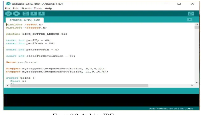
4.3 ARDUINO IDE:
Arduino is an open source computer hardware and software company, project, and user community that designs and manufactures single-board microcontrollers and microcontroller kits for building digital devices and interactive objects that can sense and control objects in the physical world.
Figure 3.2: Arduino IDE
including Universal Serial Bus (USB) on some models, which are also used for loading programs from personal computers. The microcontrollers are typically programmed using a dialect of features from the programming languages C and C++. In addition to using traditional compiler toolchains, the Arduino project provides an integrated development environment (IDE) based on the Processing language project.
V. STEPWISE PROJECT MODEL VIEW
Stepwise project design with photo view is show below, our project model design using easily avalaible material with required haedware component.
Step:1
Design model is desining using very rough construction with freely diamension. The purpose is only that show the actual concept. The time of actual design size will be defiantly reduced. The step by step progess in model of project is as show in images.it will easy to understand.
Step:2 Step:3
VI. CONCLUSION
This project aims at designing and executing the advanced development in ARDUINO for energy saving and improvement in accuracy.In todays busy life it is best solution for drawing pictures with accuracy. It is cost effective and consumes less time and as it uses ARDUINO UNO kit hence it requires less power.It can be repogrammed with real time images.
REFERENCES
[1] “A knowledge-centric Machine Tool Design & Development Process Management Framework”, International Journal of Production Research, 2014, vol. 52, no20, 6033-6051, by Linyan liu, Barrets s.calwell, Huifen wang, Ying li
vol 02, 2567- 2570, by Venkata krishna pabalu, Prof.k.n.h.shrinivas
[3] “Fabrication of Low cost 3 axis CNC Router”, International Journal of Engineering Science Invention, ISSN (online):2319-6734, ISSN (print) 2319-6726, vol 3 issue6, june2014, by Dr.J.B. Jayachandraiah, o vamsikrishna, P.abdullah khan,R.ananda Reddy
[4] “Improvement on CNC Gantry Machine Structure Design for Higher Machining Speed Capability”, International Journal of Mechanical, Aerospace, Industrial and Mechatronics Engineering, vol 9, Nov: 2015,by Ahmed a.d.sarhan, S.r.besharaty, Javed akbaria, m.hamdi
[5] “Prototype Development of Milling Machine Using CAD/CAM”, International Journal of Science And Research, ISSN 2319:7064, vol.4 issue 8 2015, by Nikita r saharkar ,Girish m dhote
[6] “ Low cost build your own three axis CNC mill prototype”, International Journal of Mechanical Engineering and Robotics, ISSN 2321-5747,vol,2 issue1,2014 by Sundar Pandian ,Raj Pandian.