Design of FFT Processor for OFDM Systems
Atul M. Borkar1, Bharti Gharde2, Poonam Wasnik3, Mohini Lambat4, Pratik Pachakate5Assistant Professor, Dept of ECE, DBACER, Nagpur, Maharashtra, India1
UG Student, Dept of ECE, DBACER, Nagpur, Maharashtra, India2
UG Student, Dept of ECE, DBACER, Nagpur, Maharashtra, India3
UG Student, Dept of ECE, DBACER, Nagpur, Maharashtra, India4
UG Student, Dept of ECE, DBACER, Nagpur, Maharashtra, India5
ABSTRACT: This paper proposes a high-speed FFT processor for orthogonal frequency-division multiplexing (OFDM) systems. This architecture uses a single-memory for a small hardware size and uses a radix-2 algorithm for high speed. The baseband multicarrier demodulation and modulation in the OFDM system is executed by using Fast Fourier Transform (FFT) and Inverse Fast Fourier Transform (IFFT). In this paper the FFT and IFFT are used to present an efficient approach which combines the short design time and flexibility of the standard cell approach. It is also used to reduce the power consumption and gives high speed of communication. By using the VLSI design the memory size and the no of complex multipliers is get reduced. So the main purpose of this project is to design an application specific integrated circuit (ASIC) FFT solution for this system. The demodulation block of the OFDM signal is multiband system which is obtained by FFT algorithm.
KEYWORDS: R2MDC, FFT, OFDM, MUX, DEMUX, Butterfly, Interblock.
I.INTRODUCTION
Now a day, there is requirement of high speed multimedia transmission in wireless communication system. So, in order to the increase the speed we are using the FFT and IFFT designs in OFDM systems. In mobile communication while transferring a data from one medium to another medium the signals contains the distortions, interference of signals and impulsive parasitic noise. Therefore there is need for good transmission of signals with a efficient bandwidth and good performance for the data or digital transmission. Now days, OFDM technique is widely used for high-speed digital communications, such as xDSL, DAB, DVB-T/H, and WLAN. As we know that for DFT/IDFT computation requires a very big and large amount of arithmetic operations, so we are using a FFT and IFFT algorithm which will reduce the arithmetic operations and also minimizes the complexity of system.
A good FFT processor should not only provide high throughput rate, but also deal with multiple data sequences effectively for MIMO OFDM applications. In our project we are using parallel and pipeline architecture. The pipeline and parallel architecture uses a butterfly algorithm to achieve a high speed communication and good performance. But the parallel and pipeline architecture needs a large area for their operations than the shared memory architecture. IN order to save the power and time we use higher radix algorithm which reduces the no of operations and complexity of system. There are mixed radix and split radix. In our project we require both types of radix. The odd indexed numbers part can use radix 2 algorithms and the even indexed numbers part can use the radix 4 algorithm. If the radix is properly chosen for different stages based on the specifications of the FFT, the optimized design for speed and area can be obtained. The radix 4 or higher radix algorithms requires less multiplications or operations than radix 2algorithm. But the data flow control is complex, hard and more data need to be fetched at the same time that will increase the area for implementation.
If the integral of the product of two signals is zero over a time period, then these two signals are said to be orthogonal to each other. These are term as orthogonality. In this work an OFDM Transceiver system is designed on a low cost FPGA Sparten3E to improve both speed and area at a time, by utilizing less number of resources in terms of slices, LUTs and multipliers of target FPGA to provide high performance cost effective solution for wireless communication applications.
II.DESCRIPTION OF FFT PROCESSOR
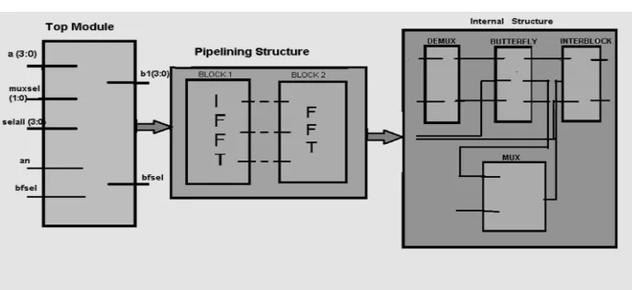
Fig. 1: This is the block diagram for design of FFT processor for OFDM system.
This is the top module of the FFT processor design. There are three main blocks of this FFT processor that are named as top module, pipelining structure and the last one is internal structure as shown in the figure.
The pipelining structure contains the FFT and IFFT blocks. The FFT is used to convert the time domain spectrum to frequency domain spectrum. Whereas, the IFFT works opposite of the FFT. It converts the frequency domain spectrum into original time domain spectrum. Again in internal structure there are MUX, DEMUX, interblock, butterfly as shown in the figure.
III.FFT AND IFFT ALGORITHEM
The FFT converts the time domain to frequency domain spectrum.
The N-point Discrete Fourier Transform (DFT) of a sequence x(n) is defined as
= −1 =0 0≤k≤N-1, (1)
Where the twiddle factor = −2 denotes N-point primitive root of unity.
The FFT analysis’s the input signals by using Decimation In Time (DIT) and Decimation In Frequency (DIF) which constructs the computational signal flow graph. The FFT used for many applications in engineering, science and mathematics. In 1994 the Gilbert strang defines the FFT as most important numerical algorithm for lifetime. The DFT is obtained by decomposing the sequence of values into components of different frequency. An FFT is the way to compute the same result more quickly. So in short it minimizes the operation of algorithm and increases the signal data speed. The best known FFT algorithm depends upon the factorization of N, but there are also FFT with complexity for all N, even for prime N. The FFT algorithms are much more accurate than evaluating the DFT definition directly.
IV. MULTIPLEXER AND DEMULTIPLEXER 1) Multiplexer:
A multiplexer is a device that selects one of several analog or digital inputs signals and forwards the selected input into single line. A multiplexer of 2^n inputs has N select lines, which are used to select which input line to send to the output. Multiplexers are mainly used to increase the amount of data that can be sent over the network within a certain
amount of time and bandwidth. A multiplexer is also called as data selector. It is also used to implement Boolean
functions of multiple variables. Larger multiplexer be constructed by using smaller multiplexer by changing them together. The 7400 series have several ICs that contain multiplexers.
2) Demultiplexer:
The data distributor is commonly known as the demultiplexer or “demux”. It totally works opposite the multiplexer. The demux takes one single input data line and then switches it to the anyone number of individual output lines one at a time. The demux converts the serial data signal at the input to a parallel data at its output lines. Some of the standard demux ICs have additional”enable output” pin which disables or prevent the input from being passed to the selected output. Also some latches built into their outputs to maintain the output logic level after the address input have been changed. However, in standard decoder type circuits the input will determine which single data output will have the same value as the data input with all other data outputs having the value of logic “0”.
Standard demultiplexer IC packages are TTL74LS138 1 to 8 ouput demultiplexer. The TTL 74LS139 dual 1 to 4 output demultiplexer or CMOS CD4514 to 1 to 16 output demultiplexer.
V. BUTTERFLY
In the FFT algorithms, a butterfly is the portion of the computation that combines the result of smaller Discrete Fourier Transform (DFTs) into a larger DFT or vice versa. The name butterfly comes from the shape of the data flow diagram in the radix 2 case. Most commonly the term “butterfly” appears the context of the Cooley-Tukey FFT algorithm, which recursively breaks down a DFT of composite size n=r^m into r smaller transforms of size m where r is the “radix” of the transforms.
The butterfly can also be used to improve the randomness of large arrays of partially random numbers, by bringing every 32 to 64 bit words into casual contact with every another word through a desired hashing algorithm, so that the change in any one bit has the possibility of changing all the bits in the large array.
Fig. 2: This is the butterfly diagram for decimation in time algorithm in FFT
FFT algorithm:
Again, the formula for IDFT is given by
These two are the main formulas for the FFT algorithm in OFDM systems. The twiddle factor plays an important role
in these equations. For each value of K, direct computation of X(k) involves N complex multiplications (4N real
multiplications) and N-1 complex additions (4N-2 real additions).
Radix-2 FFT Algorithm:
In radix 2 algorithm we divide the N point data sequence into two N/2 point data sequence as f1(n) and f2(n) corresponding to the even and odd numbers respectively. The formula is given as,
f1(n) = X2(n)
f2(n) = X(2n+1) where n = 0, 1,2 ……, (N/2 – 1)
This two are the important formulas for radix 2 FFT algorithm.
VI. PLACING THE TABLE
Real Multiplications Real Additions
N Radix-2 Radix-4 Radix-8 Split Radix Radix-2 Radix-4 Radix-8 Split Radix
16 24 20 20 152 148 148
32 88 68 408 388
64 264 208 204 196 1032 976 972 964
128 72 516 2054 2308
256 1800 1392 1284 5896 5488 5380
512 4360 3204 3076 13566 12420 12292
1024 10248 7856 7172 30728 28336 27652
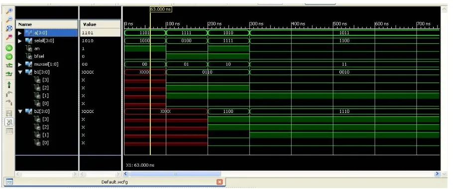
V. SIMULATION RESULT
After synthesis we find the RTL (Resister Transfer Logic); which is the schematics of OFDM
Fig. 3: RTL Schematic
Fig. 4: Internal blocks of RTL Schematic Fig. 5: Technology Schematic of FFT Processor
VI. CONCLUSION
Thus the coding for 128 point FFT is obtained by using VHDL thus by this we can increase the speed of data communication signal, minimizes the error probability and also reduces the complexity.
Our proposed variable-length FFT processor that are suitable for various MIMO OFDM-based communication systems, such as IEEE 802.11n, and IEEE 802.16 WiMAX, can perform 256/128/64/16/8 point with 1-4 data sequences. The proposed 8-point FFT processor is used for IEEE 802.11n, and the proposed 8-point FFT processor is used for IEEE 802.11n and IEEE 802.16.
REFERENCES
[1] Weidong Li, “Studies on implementation of lower power FFT processors,” Linköping Studies in Science and Technology, Thesis No. 1030,
ISBN 91-7373-692-9, Linköping, Sweden, Jun. 2003.
[2] S. He and M. Torkelson, “A new approach to pipeline FFT processor,” In Proc. of the 10th Intern.Parallel Processing Symp. (IPPS), pp. 766–
770, Honolulu, Hawaii, USA, April 1996.
[3] W.Li, L.Wanhammar, “Complex multiplication reduction in FFT processor,” SSoCC'02, Falkenberg, Sweden, Mar. 2002.
[4] M.Arioua, S.Belkouch, M.M.Hassani, “Complex multiplication reduction in pipeline FFT architecture,” In Proc. of 20th Intern. Conf. on
Computer Theory and Applications (ICCTA), Alexandria, Egypt, Oct. 2010.
[5] J.W.Cooley, J.W.Tukey, “An algorithm for the machine calculation of complex Fourier series,” Math. Computation, vol.19, pp. 297-301,
1965.