Scholarship@Western
Scholarship@Western
Electronic Thesis and Dissertation Repository
12-10-2014 12:00 AM
A New Generation of Polymer/Ceramic Composite Biomaterials
A New Generation of Polymer/Ceramic Composite Biomaterials
for Bone Regeneration
for Bone Regeneration
Mehrnaz SalarianThe University of Western Ontario
Supervisor
Prof. Paul A. Charpentier
The University of Western Ontario
Graduate Program in Biomedical Engineering
A thesis submitted in partial fulfillment of the requirements for the degree in Doctor of Philosophy
© Mehrnaz Salarian 2014
Follow this and additional works at: https://ir.lib.uwo.ca/etd
Part of the Biomaterials Commons
Recommended Citation Recommended Citation
Salarian, Mehrnaz, "A New Generation of Polymer/Ceramic Composite Biomaterials for Bone Regeneration" (2014). Electronic Thesis and Dissertation Repository. 2562.
https://ir.lib.uwo.ca/etd/2562
This Dissertation/Thesis is brought to you for free and open access by Scholarship@Western. It has been accepted for inclusion in Electronic Thesis and Dissertation Repository by an authorized administrator of
BIOMATERIALS FOR BONE REGENERATION
(Thesis format: Integrated Article)
by
Mehrnaz Salarian
Graduate Program in Biomedical Engineering
A thesis submitted in partial fulfillment of the requirements for the degree of
Doctor of Philosophy
The School of Graduate and Postdoctoral Studies The University of Western Ontario
London, Ontario, Canada
ii
Abstract
There is a substantial emerging interest for fundamental and applied research on the reinforcement of polymeric materials using nanotechnology. In the biomedical industry, development of novel bone cement composite materials with enhanced mechanical properties is of tremendous potential importance. The most universally used injectable bone cement is made of poly(methyl methacrylate) (PMMA); however, the major disadvantage of PMMA is its non-biodegradability. Polymers such as poly(propylene fumarate) (PPF) and polycaprolactone (PCL) are biodegradable, but suffer from a lack of mechanical properties. The aim of this research was to test the efficacy of these biodegradable polymers integrating nanotechnology for the development of composite biomaterials with improved mechanical properties sufficient for bone cements.
This goal was investigated through a range of different studies. Focusing on nanostructured titania (n-TiO2) initially, titania nanofibers (n-TiO2 fibers) and nanowires (n-TiO2 wires) were introduced into a PPF matrix for potential use as an orthopaedic
iii
mechanical load to the n-TiO2 fiber, leading to an increase in the mechanical properties of the bone cement composite.
Secondly, bone formation is an angiogenesis-dependent process, and the need for treatment modalities that enhance neovascularization is especially important for bone regeneration in necrotic bone. A bone cement system capable of delivering an angiogenic
modulator in a controlled manner may have the ability to boost the angiogenic response when injected to an osteonecrotic lesion. Therefore, an angiogenic agent, ginsenoside Rg1, was incorporated into an orthopedic PPF-based cement. Additionally, Sr-doped TiO2 nanofibers synthesized in supercritical CO2 were added to the cement formulation as an alternative radiopacifier to enable visualization of the bone cement composites and potential monitoring of the healing and loosening processes. XPS analysis showed that Sr2+ was doped in the crystalline matrix of anatase with the formation of SrTiO3. The strong interfacial adhesion between PPF and nanofibers were characterized by SEM, FTIR, XPS, and thermal analyses and mechanical testing. The Sr-doped n-TiO2 fibers were shown to provide reasonably higher radiopacity to the PPF matrix, which is 0.32 ± 0.03 mm Al, than the unmodified fibers at the same loading level (0.20 ± 0.01 mm Al). In addition, bone cement composites loaded with ginsenoside Rg1 were found to provide a high drug release without sacrificing the mechanical properties of the bone cement. Furthermore, tube formation bioassays suggested that human umbilical vein endothelial cell lines would rearrange and align into a tubular structure in the presence of ginsenoside Rg1. Consequently, the proposed cement combines the immediate mechanical support given by the chemical bonding between the filler/polymer and optimum radiopacity (0.30 ± 0.12 mm Al) due to the incorporation of the Sr-doped TiO2 nanofibers to PPF matrix.
Thirdly, because of the unique biological activities of ginsenoside Rg1, upregulating in vitro proliferation, migration, chemo-invasion, and tube formation in human umbilical vein endothelial cells (HUVECs), Rg1 can be incorporated into scaffold materials for
iv
microspheres were characterized by SEM, showing unimodal 50-65 µm size diameters using the microfluidic technique, ideal for easy flowing powders required in commercial formulations. The PPF microspheres produced from the microfluidic technique gave high encapsulation efficiencies of up to 95.35 ± 0.82%, while those obtained from a conventional double emulsion method gave a much broader size distribution in the range
of 2-45 µm with lower encapsulation efficiencies of 78.48 ± 1.68%. Release profiles were studied and quantified by UV-Vis spectrophotometry, with the results showing a lower initial burst in the release of Rg1 from the unimodal microspheres prepared by the microfluidic technique than from the double emulsion method. The burst effect was followed by a slow release profile which can be used for long term drug delivery applications to maintain the ginsenoside Rg1 concentration for an extended time period. Moreover, the released Rg1 showed a significant stimulatory effect on angiogenesis behavior and tube formation in human umbilical vein endothelial cells (HUVECs). Therefore, PPF microspheres developed in this study have potential for next-generation biomedical agents in drug-release devices for bone tissue engineering.
Finally, the use of hydroxyapatite HAp is rather limited for heavy load-bearing applications due to low mechanical reliability and poor processability. Therefore, immobilization of a biocompatible metal/metal oxide on the surface of HAp has been receiving increased attention for applications involving the enhancement of mechanical properties of biocompatible prostheses. A novel nanostructured HAp and a composite of HAp and TiO2 with ultrafine structure and significantly improved mechanical properties were prepared using combined co-precipitation and sol-gel method in the green solvent, scCO2, and incorporated into poly(ε-caprolactone) (PCL) matrix to develop scaffolds with enhanced physical and mechanical properties for bone regeneration. SEM and TEM analyses were employed to examine the morphology of the HAp nanoplates and HAp-TiO2 nanocomposites. The presence of Ti, O, Ca, and P in the HAp-TiO2 nanocomposites
v
synthesized nanomaterials. Mechanical testing revealed a significant increase in the Young’s modulus (88.6%), tensile strength (122%), flexural modulus (47%), and flexural
strength (59.6%) of PCL/HAp-TiO2 composites containing 20 wt % HAp-TiO2 compared to PCL/HAp composites.
Keywords
vi
Co-Authorship Statement
This dissertation is prepared in the integrated article format. Manuscripts that have been previously published, or submitted for publication, or finalized for submission form the body of this dissertation which are presented with some adjustments in Chapters 2 through 6.
Title: Synthesis and characterization of novel TiO2-poly(propylene fumarate) nanocomposites for bone cementation (Chapter 2). Authors: Mehrnaz Salarian, William Z. Xu, Mark C. Biesinger, Paul A. Charpentier. The experimental work was conducted by Mehrnaz Salarian under the guidance of advisor Dr. Paul A. Charpentier. XPS analyses were performed by Dr. Mark Biesinger. NMR measurements and help with interpretation were done with Dr. William Z. Xu. The draft of this manuscript was written by Mehrnaz Salarian with the great help of Dr. Mark C. Biesinger in the discussion. Modifications were carried out under the close supervision of Dr. Paul A. Charpentier. The final version of this article was published by the Journal of Materials Chemistry B 2 (2014) 5145-5156.
Title: Delivery of an angiogenic mediator for bone regeneration in a radiopaque Sr2+ -modified TiO2/poly(propylene fumarate) based bone cement (Chapter 3). Authors:
Mehrnaz Salarian, William Z. Xu, Richard Bohay, Edmund M. K. Lui, and Paul A. Charpentier. The experimental works were conducted by Mehrnaz Salarian under the guidance of advisor Dr. Paul A. Charpentier. Radiopacity measurements set up and calculations were performed under the direct guidance of Dr. Richard Bohay. The biological works were done by Mehrnaz Salarian under the guidance of Dr. Edmund M. K Lui. The draft of this manuscript was written by Mehrnaz Salarian and corrected by Dr. Paul A. Charpentier and William Z. Xu This manuscript is manuscript is under preparation for publication.
Title: Fabrication of monodisperse ginsenoside Rg1-loaded PPF microspheres using a
vii
Charpentier. The experimental works were conducted by Mehrnaz Salarian under the guidance of advisor Dr. Paul A. Charpentier. Dr. Raziye Samimi helped in the experimental set up and design. XANES data measurements facilities were provided by Dr. Tsun-Kong Sham and interpretations were done Dr. Zhiqiang Wang. The biological works were done by Mehrnaz Salarian under the guidance of Dr. Edmund M. K Lui. The
draft of this manuscript was written by Mehrnaz Salarian and corrected by Dr. Paul A. Charpentier. This manuscript is under preparation for publication.
Title: Hydroxapatite-TiO2-based nanocomposites synthesized in supercritical CO2 for bone tissue engineering: physical and mechanical properties (Chapter 5). Authors:
viii
Dedication
ix
Acknowledgments
I would like to express my grateful appreciation to my advisor Professor Paul A. Charpentier for for his supervision, insight, advice, and guidance throughout all stages of this research. The completion of this dissertation would not have been possible without his incomparable support and encouragement.
I gratefully thank Dr. Edmund M. K. Lui and Dr. Hua Pei for their impressive advice and helps in biological studies of ginsenoside Rg1. I would like to express my sincere gratitude to Dr. Richard Bohay of Dentistry department, UWO for X-ray Radiography, Dr. Mark Besigner of the Surface Science Western, UWO for his expert work on the XPS analyses, Dr. Todd Simpson of Nanofabrication laboratory, UWO for SEM, Dr. Carmen Andrei of Brockhouse Institute, McMaster University, for HRTEM, Ms. Aneta Borecki of the Department of Chemistry, UWO for the powder XRD, and Mr. Ross Davidson of the Surface Science Western, UWO for SEM work. Many thanks go to Ms. Dong Zhao of the University of Saskatchewan for the XANES data measurements.
I have been indebted to Dr. William Xu, the postdoctoral fellow of the research group, for
his invaluable advice, constructive comments, and scientific discussions. I gratefully thank Dr. Tsun-Kong Sham and Dr. Zhiqiang Wang for providing us with XANES measurements facilities and interpretations. I also would like to appreciate the assistance of Dr. Jun Yang and Dr. Tingjie Li in microfluidic studies design and preparation.
I would also thank all my colleagues in Charpentier's Lab, Dr. Nasrin Farhangi, Dr. Lijuan Yang, Dr. serge ayissi, Chao Chen, Qasem Alsharari, and Koosha Azhie for their cooperation, friendship, and help.
x
xi
Table of Contents
Abstract ... ii
Co-Authorship Statement ... vi
Dedication ... viii
Acknowledgments ... ix
Table of Contents ... xi
List of Tables ... xvi
List of Figures ... xvii
List of Appendices ... xxiii
List of Abbreviations, Symbols, Nomenclature ... xxiv
Chapter 1 ... 1
1 General Introduction and Literature Review ... 1
1.1 Vascular necrosis of femoral head... 1
1.2 Cementation... 5
1.2.1 PMMA-based bone cements ... 6
1.2.2 Poly(propylene fumarate)-based bone cements and properties ... 8
1.3 Angiostimulating activity of ginsenoside Rg1 ... 16
1.4 Inorganic reinforcing agents ... 18
1.4.1 Hydroxyapatite ... 18
1.4.2 Hydroxyapatite/titania nanocomposites ... 20
1.4.3 Titania ... 21
1.4.4 Synthesis of nanostructured materials in supercritical CO2 ... 22
1.5 Microencapsulation of bioactive molecules into a polymer matrix ... 23
xii
1.6 Scope of the research ... 25
1.7 References ... 27
Chapter 2 ... 40
2 Synthesis and Characterization of Novel TiO2-Poly(propylene fumarate) Nanocomposites for Bone Cementation ... 40
2.1 Introduction ... 41
2.2 Experimental details ... 43
2.2.1 Materials ... 43
2.2.2 Characterization ... 44
2.2.3 Preparation of materials ... 45
2.3 Results and Discussion ... 50
2.3.1 Synthesis of poly(propylene fumarate) (PPF) ... 50
2.3.2 Preparation of TiO2-PPF nanocomposites and bone cement composites . 54 2.3.3 Mechanical properties of crosslinked PPF and bone cement composites . 62 2.4 Conclusions ... 66
2.5 References ... 68
Chapter 3 ... 72
3 Delivery of an angiogenic mediator for bone regeneration in a radiopaque Sr-doped TiO2/poly(propylene fumarate) based bone cement ... 72
3.1 Introduction ... 73
3.2 Experimental details ... 76
3.2.1 Materials ... 76
3.2.2 Characterization ... 77
3.2.3 Preparation of materials ... 81
xiii
3.3.1 X-ray diffraction analysis of Sr-doped TiO2 nanoparticles synthesized
in supercritical CO2 ... 88
3.3.2 Scanning electron microscopy (SEM) and energy-dispersive X-ray spectroscopy (EDX) analyses of Sr-doped TiO2 nanoparticles synthesized in supercritical CO2 ... 90
3.3.3 X-ray photoelectron spectroscopy (XPS) measurement of Sr-doped TiO2 and Sr2+-TiO2/PPF nanocomposites nanocomposites ... 91
3.3.4 Fourier transform infrared (FTIR) spectroscopy of Sr2+-TiO2/PPF nanocomposites ... 94
3.3.5 TGA ... 95
3.3.6 Mechanical testing (tensile and flexural strength and modulus) ... 96
3.3.7 Radiopacity ... 100
3.3.8 Angiogenesis effect/tube formation of HUVEC cell line ... 101
3.3.9 In vitro drug release behavior of Rg1 ... 103
3.4 Conclusions ... 106
3.5 References ... 107
Chapter 4 ... 113
4 Encapsulation of ginsenoside Rg1 within PPF Microspheres using Microfluidic Technique ... 113
4.1 Introduction ... 114
4.2 Experimental details ... 117
4.2.1 Materials ... 117
4.2.2 Characterization of PPF microspheres encapsulating ginsenoside Rg1 .. 118
4.2.3 Preparation of materials ... 119
4.2.4 Determination of encapsulation efficiency (EE) of Rg1-loaded PPF microspheres ... 122
4.2.5 In vitro release of ginsenoside Rg1 ... 123
xiv
4.3 Results and Discussion ... 124
4.3.1 Surface morphology and particle size analysis of the Rg1-loaded PPF microspheres ... 124
4.3.2 Encapsulation efficiency of Rg1 in the PPF microspheres ... 126
4.3.3 Fourier transform infrared (FTIR) spectroscopy of Rg1, PPF, and Rg1-loaded PPF microspheres ... 127
4.3.4 X-ray diffraction analysis of Rg1, placebo PPF microspheres, and Rg1 -loaded PPF microspheres ... 128
4.3.5 XANES spectroscopy of Rg1, PPF, and Rg1-loaded PPF microspheres . 129 4.3.6 Release of ginsenoside Rg1 from delivery system in vitro ... 131
4.3.7 Angiogenesis effect/tube formation of HUVEC cell line ... 133
4.4 Conclusions ... 136
4.5 References ... 138
Chapter 5 ... 142
5 Hydroxapatite-TiO2-based Nanocomposites Synthesized in Supercritical CO2 for Bone Tissue Engineering: Physical and Mechanical Properties ... 142
5.1 Introduction ... 143
5.2 Experimental details ... 145
5.2.1 Materials ... 145
5.2.2 Characterization ... 145
5.2.3 Preparation of materials ... 147
5.3 Results and Discussion ... 150
5.3.1 SEM and TEM characterization of the as-synthesized HAp and calcined HAp-TiO2 composites powders ... 150
5.3.2 EDS analysis of HAp and HAp-TiO2 nanocomposites ... 154
5.3.3 XRD analysis of HAp and HAp-TiO2 nanocomposites ... 156
xv
5.3.5 BET analysis of HAp and HAp-TiO2 nanocomposites synthesized in
supercritical CO2 ... 159
5.3.6 XPS measurements of HAp and HAp-TiO2 nanocomposites synthesized in supercritical CO2 ... 161
5.3.7 XANES spectroscopies of TiO2, HAp, and HAp-TiO2 nanocomposites synthesized in supercritical CO2 ... 164
5.3.8 TGA of HAp and HAp-TiO2 nanocomposites ... 167
5.3.9 Mechanical properties of PCL/HAp and PCL/HAp-TiO2 composites .... 169
5.4 Conclusions ... 172
5.5 References ... 174
Chapter 6 ... 179
6 Conclusions and Recommendations ... 179
6.1 Conclusions ... 179
6.2 Recommendations ... 182
Appendices ... 185
Appendix A. Calibration curve of Rg1 ... 185
Appendix B. Copyright releases. ... 186
xvi
List of Tables
Table 1.1. ARCO international classification of osteonecrosis.[24] ... 4
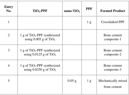
Table 2.1. Formulation of the TiO2-PPF nanocomposites. ... 48
Table 2.2. Formulation of the bone cement composites. ... 49
Table 2.3. Mechanical Properties of the crosslinked PPF and the synthesized bone cement composites. ... 64
Table 3.1. Formulation of the Sr2+-TiO2/PPF nanocomposites. ... 85
Table 3.2. The different compositions for the bone cement composites in each system. 87
Table 3.3. Elemental composition of Sr-doped TiO2 nanofibers (n = 3, mean ± SD). .... 91
Table 3.4. Radiopacity values (mm Al) of bone cement composites of equivalent Al thickness (means ± SD). ... 100
Table 5.1. Synthesis conditions of HAp and HAp-TiO2 nanostructures in scCO2 and characterization results (morphology and BET surface area). ... 151
Table 5.2. Ca/P atomic ratio of HAp powders and HAp-TiO2 nanocomposites. ... 156
Table 5.3. Atomic percentage of the elements detected in the HAp-2 and HAp-TiO2-2 samples. ... 162
xvii
List of Figures
Figure 1.1. The lack of normal blood supply to the femoral head causes the bone to die. 2
Figure 1.2. The operative procedure of cementation for osteonecrosis of femoral head. .. 6
Figure 1.3. Cross-linking reaction of PPF and PPF-DA to synthesize PPF/PPF-DA polymer networks.[45] ... 9
Figure 1.4. Degradation scheme of PPF/PPF-DA networks.[57] ... 10
Figure 1.5. Multi-step process of blood vessels formation. ... 15
Figure 1.6. The schematic overview of ginsenoside Rg1-mediated angiogenic action in HUVEC. ... 17
Figure 1.7. Crystal structure of stoichiometric hydroxyapatite. ... 20
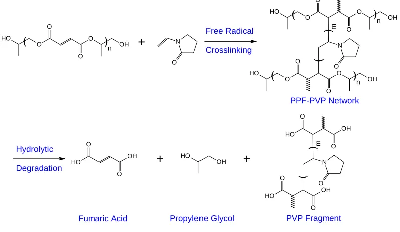
Figure 2.1. Crosslinking and degradation scheme of PPF-PPF-PVP networks. ... 42
Figure 2.2. Synthetic Scheme for the Preparation and Functionalization of PPF. ... 51
Figure 2.3. A comparison of 1H NMR spectra of (a) propylene glycol, (b) the synthesized PPF, and (c) MA-PPF in CDCl3. ... 52
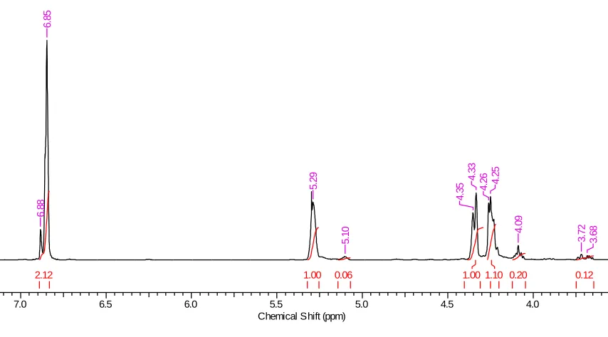
Figure 2.4. 1H NMR spectrum of the synthesized PPF in CDCl3 showing integrals of the peaks. ... 53
Figure 2.5. A comparison of 13C NMR spectra of (a) propylene glycol, (b) the synthesized PPF, and (c) MA-PPF in CDCl3 ... 54
Figure 2.6. (a) SEM and (b) TEM images and the distribution of (c) diameter and (d) aspect ratio of the synthesized TiO2 nanofibers. ... 55
xviii
Figure 2.8. ATR-FTIR spectra of (a) TiO2, (b) PPF, (c) TiO2-PPF nanocomposite, and (d) crosslinked bone cement composite. ... 57
Figure 2.9. Binding modes of RCOO- with TiO2 surface (R= H or CH3). ... 58
Figure 2.10. High resolution XPS record of C 1s region of (a) PPF and (b) MA-PPF, high resolution XPS record of O 1s region of (c) PPF and (d) MA-PPF, (e) XPS full-scan
spectrum of the TiO2-PPF nanocomposite, high resolution XPS scan of the C 1s region of (f) the TiO2-PPF nanocomposite and (g) the mechanically mixed TiO2-PPF nanocomposite, high resolution XPS scan of the O 1s region of (h) the TiO2-PPF nanocomposite, and high resolution XPS scan of the Ti 2p region of (i) the TiO2-PPF nanocomposite. ... 60
Figure 2.11. TGA curves of: (a) TiO2, (b) PPF, (c) crosslinked PPF, (d) TiO2-PPF nanocomposite (synthesized using 1 g of MA-PPF and 0.0250 g of TiO2) and (e) crosslinked bone cement composite (made of 1 g of TiO2-PPF synthesized using 0.0250 g of TiO2). ... 61
Figure 2.12. Derivative thermogravimetric (DTG) curves of: (a) PPF, (b) crosslinked PPF, (c) (d) TiO2-PPF nanocomposite (synthesized using 1 g of MA-PPF and 0.0250 g of TiO2) and (e) crosslinked bone cement composite (made of 1 g of TiO2-PPF synthesized using 0.0250 g of TiO2). ... 62
Figure 2.13. SEM images of the fracture planes of (a) crosslinked unmodified PPF, (b) bone cement composite-1, (c) crack bridging within the bone cement composite-1, and (d) bone cement composite-2. ... 66
Figure 3.1. Synthetic scheme for the preparation and functionalization of PPF and the synthesis of Sr2+-TiO2/PPF nanocomposite and bone cement composite. ... 84
xix
Figure 3.3. SEM images of (a) the 5 wt% Sr-doped TiO2 and (b) the 20 wt% Sr-doped TiO2 and EDX Spectra of (c) the 5 wt% Sr-doped TiO2 and (d) the 20 wt% Sr-doped TiO2. ... 91
Figure 3.4. (a) XPS full-scan spectrum of the Sr-doped TiO2 nanoparticles, high resolution XPS record of O 1s region (b), high resolution XPS scan of the Ti 2p region
(c), and high resolution XPS scan of the Sr 3d region (d) of the Sr-doped TiO2 nanoparticles and high resolution XPS record of the C 1s region (e), high resolution XPS record of the O 1s region (f), high resolution XPS scan of the Ti 2p region (g), and high resolution XPS scan of the Sr 3d region (h) of the Sr2+-TiO2/PPF nanocomposite-3. ... 93
Figure 3.5. ATR-FTIR spectra of (a) PPF, (b) Sr2+-TiO2/PPF nanocomposite-3, and (c) crosslinked bone cement composite-3. ... 95
Figure 3.6. (A) TGA curves of: (a) TiO2, (b) PPF, (c) crosslinked PPF, (d) Sr2+ -TiO2/PPF nanocomposite-3 (synthesized using 1 g of MA-PPF and 0.015 g of Sr-doped TiO2), and (e) crosslinked bone cement composite-3 (made of 1 g of Sr2+-TiO2/PPF synthesized using 0.015 g of Sr-doped TiO2). (B) Derivative thermogravimetric (DTG) curves of: (a) PPF, (b) crosslinked PPF, (c) Sr2+-TiO2/PPF nanocomposite-3 (synthesized using 1 g of MA-PPF and 0.015 g of Sr-doped TiO2), and (d) crosslinked bone cement composite-3 (made of 1 g of Sr2+-TiO2/PPF synthesized using 0.015 g of Sr-doped TiO2). ... 96
Figure 3.7.Mechanical properties of cross-linked bone cement composites as a function of the Sr-doped TiO2 nanofibers concentration. ... 98
Figure 3.8.SEM images of the fracture planes of: (a) crosslinked unmodified PPF, (b-d) bone cement composite-2, and (e) bone cement composite-3 (the arrows show Sr-doped TiO2 nanofibers are agglomerating at higher concentrations within the polymer matrix).99
xx
Figure 3.10. The cumulative amount of released ginsenoside Rg1 from Rg1-loaded bone cement composite-1, Rg1-loaded bone cement composite-2, and Rg1-loaded bone cement
composite-3. ... 105
Figure 4.1. Chemical structure of (a) ginsenoside Rg1 and (b) PPF ... 117
Figure 4.2. Schematic of the double emulsion method. ... 120
Figure 4.3. Schematic of the microfluidic system. ... 122
Figure 4.4. SEM images of Rg1-loaded PPF microspheres from (a, b) double emulsion method and (c, d) microfluidic method where the continuous phase flow rate and disperse phase flow rate was 0.1 and 0.01 ml/min, respectively, and (e, f) microfluidic method where the continuous phase flow rate and disperse phase flow rate was 0.2 and 0.01 ml/min, respectively. ... 125
Figure 4.5. Image J number of size distributions for Rg1-loaded PPF microspheres. ... 126
Figure 4.6. FTIR spectra of (a) ginsenoside Rg1, (b) PPF, and (c) Rg1-loaded PPF microspheres prepared using microfluidic method. ... 128
Figure 4.7. XRD patterns of (a) background, (b) placebo PPF microspheres prepared using microfluidic method, (c) ginsenoside Rg1, and (d) Rg1-loaded PPF microspheres prepared using microfluidic method. ... 129
Figure 4.8. (a) C K-edge XANES spectra of pure PPF microspheres, ginsenoside Rg1, and Rg1-loaded PPF microspheres prepared using microfluidic method. (b) Linear fitting of the Rg1-loaded PPF microspheres prepared using microfluidic method. Inset shows the π* resonance. ... 131
Figure 4.9. Release profiles of ginsenoside Rg1 from monodisperse PPF microspheres. ... 133
xxi
Figure 5.1. Schematic representation of the preparation of HAp precursor. ... 149
Figure 5.2. Schematic representation of sol-gel process for producing HAp-TiO2 composites... 149
Figure 5.3. SEM images of the (a) TiO2 nanotubes calcined at 450 °C, (b) as-prepared HAp-1 nanoplates, (c) as-prepared HAp-2 nanoplates, (d) HAp-TiO2-1 nanocomposites
calcined at 500 °C, (e) TiO2-2 nanocomposites calcined at 500 °C, and (f) HAp-TiO2-h nanocomposites and TEM images of (g) HAp-TiO2-2 nanocomposites calcined at 500 °C and (h) HAp-TiO2-h nanocomposites. Arrows in Figure 5.3c indicate the voids between aggregates of plate-like HAp secondary particles. ... 154
Figure 5.4. EDS elemental mapping of HAp-TiO2-2 nanocomposites: (a) selected area on the sample, (b) O mapping, (c) Ti mapping, (d) P mapping, and (e) Ca mapping. ... 154
Figure 5.5. EDS elemental mapping of HAp-TiO2-h nanocomposites: (a) selected area on the sample, (b) O mapping, (c) Ti mapping, (d) P mapping, and (e) Ca mapping. ... 155
Figure 5.6. EDX spectra of the (a) HAp-2 and (b) HAp-TiO2-2 nanocomposites. ... 156
Figure 5.7. XRD patterns of the (a) HAp-2, (b) HAp-TiO2-2, and (c) HAp-TiO2-h nanocomposites. In Figure 5.7b&c, filled triangles are representing the prominent characteristic peaks of anatase TiO2. ... 158
Figure 5.8. Fourier transform infrared (FTIR) spectroscopy of the (a) 2, (b) HAp-TiO2-2, and (c) HAp-TiO2-h nanocomposites. ... 159
Figure 5.9. N2 adsorption/desorption isotherm of the (a) HAp-2 and (b) HAp-TiO2-2 nanocomposites. ... 160
xxii
Figure 5.11. Ti L3,2-edge XANES spectra of the (a) TiO2 nanoparticles calcined at 450 °C, (b) TiO2 nanoparticles calcined at 750 °C, and (c) HAp-TiO2-2 nanocomposite. ... 165
Figure 5.12. Ca L3,2-edge XANES spectra of the (a) HAp and (b) HAp-TiO2-2 nanocomposite powders. ... 166
Figure 5.13. (I) O K-edge XANES spectra of the (b) HAp-TiO2-2 nanocomposites in comparison with (b) HAp-2, (c) TiO2 nanoparticles calcined at 450 °C, and (d) TiO2 nanoparticles calcined at 750 °C. (II) O K-edge linear fitting of the HAp-TiO2-2 nanocomposites. ... 167
Figure 5.14. TGA spectrum of (a) HAp-2, (b) HAp-TiO2-2 nanocomposites, and (c) HAp-TiO2-h nanocomposites... 169
xxiii
List of Appendices
Appendix A. Calibration curve of Rg1 ... 185
xxiv
List of Abbreviations, Symbols, Nomenclature
Abbreviations
AcOH Acetic acid
ARCO Association Research Circulation Osseous
AL Actual drug loading
Al2O3 Alumina
BET method Brunauer-Emmet-Teller method bFGF Basic fibroblast growth factor
BMSCs Bone marrow stromal cells
BMP-2 Bone morphogenic protein-2
BPO Benzoyl peroxide
CaP Calcium phosphate
CT Computed tomography
DCM Dichloromethane
1D One dimensional
3D Three-dimensional
DMA Dynamic mechanical analyzer
DMAP 4-dimethylaminopyridine
DMT N-dimethyl-p-toluidine
DTG Derivative thermogravimetric
EDX Energy-dispersive x-ray spectroscopy
EE Encapsulation efficiency
eNOS Endothelial nitric oxide synthase FGFR-1 Fibroblast growth factor receptor-1
FTIR Fourier transform infrared spectroscopy
FS Flexural strength
FM Flexural modulus
GR Glucocorticoid receptor
xxv
HUVEC Human umbilical vein endothelial cells
MA Maleic anhydride
NMR Nuclear magnetic resonance
NO Nitric Oxide
N-VP N-vinyl-2-pyrrolidinone
PBS Phosphate buffered solution
PCL Poly(ε-caprolactone)
PDMS Poly(dimethylsiloxane)
PLGA Poly(lactic-co-glycolic acid)
PLLA Poly(L-lactic acid) (PLLA)
PMMA Poly(methyl methacrylate)
PPF Poly(propylene fumarate)
PPF-DA poly(propylene fumarate)-diacrylate
PVA Poly (vinyl alcohol)
PVP Poly(N-vinyl pyrrolidone)
scCO2 Supercritical CO2
SCF Supercritical fluids
SEM Scanning electron microscope
SWNTs Single-walled carbon nanotubes SFE Supercritical fluid extraction
TCP Tricalcium phosphate
TEM Transmission electron microscopy
TGA Thermogravimetric analysis
THF Tetrahydrofuran
THR Total hip replacement
n-TiO2 fibers Titania nanofibers
TIP Titanium isopropoxide
TRD Texas red dextran
TTCP Tetracalcium phosphate
UV-Vis Ultraviolet-visible
VEGF Vascular endothelial growth factor XANES X-ray absorption near edge structure
xxvi
XRD X-ray diffraction
ZrO2 Zirconium dioxide
Symbols
P Pressure (psi)
Pc Critical pressure (psi)
Tc Critical temperature (°C)
Chapter 1
1
General Introduction and Literature Review
1.1
Vascular necrosis of femoral head
Blood circulation is a key factor to have healthy bone tissue, since it transports oxygen, nutrition, carbon dioxide, waste, and other materials to and from bone cells.[1] However, there are many risk factors which can cause the temporary or permanent loss of blood supply to bone. Reduced blood flow to bones will result in osteonecrosis, which mainly occurs in the weight-bearing parts of the body, for example the anterosuperior aspect of the femoral head, as shown in Figure 1.1.[2] Osteonecrosis is a disease with a wide ranging etiology and poorly understood pathogenesis,[3] being most common in adults between the ages of 20 and 50 years.[4] Regardless of what causes the death of the bone cell, the cellular events and therefore the tissue responses constituting the repair are the same whether the cells are killed by interfering with their blood supply, by freezing them, or killing them with cytotoxic chemical agents.[5] Because of this common path for repair and the fact that the actual cause of cell death is unknown in most cases, the term “osteonecrosis” is used rather than “avascular necrosis”, which indicates a distinct
Figure 1.1. The lack of normal blood supply to the femoral head causes the bone to die.
Etiology is the study of the factors that cause a disease. Trauma-induced avascular necrosis of the femoral head represents the most common type of aseptic osteonecrosis.[6] With the stress of weight-bearing, the necrotic segment of bone is likely to collapse leading to painful degenerative arthritis of the hip.[7] Therefore, the term “avascular necrosis” is exclusively used for this post-traumatic group, as they originate in
towards avascular necrosis than men.[12] Besides, there is a higher number of avascular necrosis incidence among patients with a higher level of activity before fracture.[6]
Pathogenesis deals with the cellular events, reactions, and other pathological mechanisms happening in the progression and development of a disease.[2] Multiple theories about the mechanism of interruption of the blood supply to the femoral head have been
formulated.[2, 8] Some of these theories comprise thromboemboli in the blood supply to bone resulting from circulating fat or nitrogen bubbles,[15] abnormally shaped red blood cells causing sickle-cell anaemia,[16] infection and vasculitis leading to vessel wall injury,[2] and radiation damage or release of vasoactive factors as in Gaucher disease.[17]
Osteonecrosis of the femoral head leads to end-stage degenerative arthritis, which is responsible for approximately 10% of the primary total hip arthroplasties performed in the United States.[18] If no treatment is applied, more than 70% of osteonecrotic femoral heads will collapse and require prosthetic replacement within three to four years of diagnosis.[19] In early stages of osteonecrosis, the goal is to avoid collapse.[20] Present surgical treatments such as core decompression and bone grafting have been the most effective treatments for necrosis of the femoral head at an early stage.[4] However, these methods consume time for biologic incorporation of bone graft, revascularization, or replacement of dead bone by creeping substitution, and are less efficacious in Stages III and IV.[20] When lesions are large and collapse has already occurred, the goal is to halt additional collapse and to restore femoral head sphericity.[21] Bone grafting techniques are less successful at joint restoration once collapse occurs (Stage III osteonecrosis), so the open reduction and cement fixation (cementation) can be more efficacious;[4, 20] total hip arthroplasty is the most successful treatment for Stage IV.[22]
The Association Research Circulation Osseous (ARCO) international classification system classifies osteonecrosis into five stages (0-IV) using computer tomography (CT)
normal radiographs and CT scans with positive MRI or scintigraphic findings or both, and they are treated by core decompression. In Stage II osteonecrosis, a mottled and sclerotic rim around the area of necrosis is evident in radiographs and CT scans in addition to the MRI changes diagnostic for osteonecrosis. These patients are treated with vascularized free fibular grafts. Based on the location and extent of infarct size, Stages I
and II are subcategorized into three types (A, B, and C). Patients with Stage III osteonecrosis show a crescent sign, flattening, or both in radiographs and CT scan, and they are treated by open reduction and cementation. Stage III is also subdivided (A, B, and C) using the quantification of collapse.[20] In Stage IV osteonecrosis, arthritic findings become evident, and total hip arthroplasty is the most successful treatment for Stage IV.[20]
1.2
Cementation
Cement fixation is a recently introduced method for treating stage III osteonecrosis of femoral heads. Bone cementation involves the injection of fluid material, which instantly hardens in the defect, and provides mechanical support to prevent collapse.[20] Bone cement is considered to make the treatment of irregular defects easier. It is also easier to use for clinical practice, providing immediate symptomatic relief and faster recovery of the patient, while allowing improvement in mobility.[23, 25] Cement augmentation has the potential to maintain reduction and restore femoral head sphericity and prevent further collapse before progression to stage IV disease.[21, 25] However, the long term results in regard to progression of disease and secondary arthritis is unknown. The possible indication for this procedure is a young patient with stage III osteonecrosis who has active, unresolved disease.[4, 20]
The procedure is performed with the patient in the lateral decubitus position. A 20-cm incision is made centered over the greater trochanter, and a T-shaped capsulotomy is made at the base of the femoral neck. Using a skeletal traction device, subluxation and
distraction of the femoral head and observation of the pathologic area of articular cartilage is performed. Then, a 6-mm hole is drilled in the neck (Figure 1.2(A)), which allows access for debridement of dead bone and insertion of cement. A joker is used to
Figure 1.2. The operative procedure of cementation for osteonecrosis of femoral head.
A small burr hole is created at the base of the cartilage allowing for debridement of necrotic bone and access for the cement (small arrow). Cartilage deformity is shown (large arrow) (A). A small bone dowel taken from the greater trochanter is placed in the entry hole (small arrow). The cartilage deformity has been reduced (large arrow) (B).[20]
1.2.1
PMMA-based bone cements
of PMMA in cement augmentation for the treatment of stage III vascular necrosis of the femoral head in 2000, and found that the use of this procedure should be restricted to symptomatic, young patients (less than 40 years), preferably with mild to moderate Stage III osteonecrosis.[4]
1.2.1.1
Drawbacks associated with PMMA
PMMA is reportedly bioinert and shows good biocompatibility over long-term follow-up.[34] Several inherent advantages to PMMA include familiarity for operating physicians, ease of handling, good biomechanical strength and stiffness, and cost-effectiveness.[35] However, there are several disadvantages associated with PMMA bone cements.[26] Firstly, PMMA is nonbiodegradabile; thus, it cannot be replaced with new bone formation.[36, 37] Secondly, the high exothermic reaction during polymerization,
ranging between 67 and 124 C at the center of the cement mantle in vivo results in
impaired local blood circulation and thermal necrosis of the surrounding bone at the cement-bone interface.[38] Thirdly, the release or leakage of unreacted monomer liquid before polymerization of the cement in the bone bed may cause chemical necrosis of the bone.[38] Forthly, the foreign body reaction at the cement-bone interface indicates that PMMA cement is not bioinert and biocompatible. The cellular responses or tissue reactions might be associated with the chemical effects from unreacted MMA monomer produced during the setting process, and may be involved as the possible cause of junctional tissue damage and cement loosening.[36] According to Herman et al., PMMA cement particles evoke inflammatory periprosthetic tissue responses directly affecting the bone resorption at the cement-bone interface.[39] Fifthly, PMMA bone cements suffer from shrinkage during polymerization.[38] In addition, toxic substances or unreacted
1.2.2
Poly(propylene fumarate)-based bone cements and properties
Recently, poly(propylene fumarate) (PPF) has attracted considerable interest as a promising degradable material for treating skeletal defects.[40] PPF is a linear and
unsaturated polyester made of repeating units, which contain one unsaturated carbon-carbon double bond allowing for cross-linking of the polymer into a covalent polymer network and two ester linkages for hydrolysis of the polymer into biocompatible products
fumaric acid and propylene glycol, both of which can be absorbed by the body.[41, 42] Cross-linked PPF is often incorporated with calcium phosphates found to provide comparable mechanical properties to those of human trabecular bone.[43] Although the double bonds of PPF can cross-link with itself to form cross-linked polymer networks,[44] a variety of cross-linking agents such as N-vinyl pyrrolidinone (N-VP), poly(propylene fumarate)-diacrylate (PPF-DA), poly(ethylene glycol)-dimethacrylate (PEG-DMA), diethyl fumarate, and methylmethacrylate (MMA) have been explored in combination with PPF.[45] When combined with an appropriate initiator system, it may be cross-linked in situ during surgery to form a solid biodegradable bone cement via an addition polymerization reaction between PPF and cross-linking reagents.[46] The chemical structure of PPF and PPF-DA and cross-linking reaction of PPF and PPF-DA are shown in Figure 1.3. As the cross-linking reaction proceeds, the viscous polymer is transformed to a putty-like state before solidifying. During this transition, the material may be injected or molded into a bone defect. It is particularly interesting for orthopaedic applications in filling irregularly shaped bone defects, which are relatively inaccessible, with minimal surgical intervention.[41] Addition polymerization reactions are generally exothermic as in the case of PMMA bone cements, which may cause some local tissue
necrosis. In the case of PPF with N-VP used as a cross-linker, the generated heat by the addition polymerization reaction between PPF and N-VP is milder with no local tissue necrosis noted in vivo after implantation compared to the curing temperature measured for PMMA bone cement.[47] For example, the maximum cross-linking temperature reported for a range of formulations based on PPF, N-VP, benzoyl peroxide, and
tricalcium phosphate (TCP) varied from 38 to about 48 C.[48, 49] Besides, the curing
The properties of cross-linked PPF networks, including mechanical strength, degradation kinetics, and handling of the polymer are dependent on the molecular characteristics of the constituent polymer, including the molecular weight and polydispersity of PPF.[46] It has been reported that achieving high molecular weight PPF is difficult. Typically PPF molecular weights vary from 500 to 4,000 Da, and polydispersities are generally below
1.4.[46] The major disadvantage of PPF is that it is a viscous liquid at room temperature, which makes handling of the polymer somewhat cumbersome.[50] As PPF molecular weight increases, its viscosity also increases, which often impacts the handling of the polymer and the intended applications.[46] Furthermore, a higher molecular weight PPF and a more viscous polymer solution may cause greater autoacceleration of the polymerization, leading to rapid release of heat.[48] However, the total heat released upon crosslinking decreased by an increase in PPF molecular weight.[51]
Figure 1.3. Cross-linking reaction of PPF and PPF-DA to synthesize PPF/PPF-DA
polymer networks.[45]
PPF-based materials undergo only bulk degradation by hydrolysis of the ester linkages within its chemical structure.[52] PPF degrades to fumaric acid, a naturally occurring substance, found in the tri-carboxylic acid cycle (Krebs cycle), and propylene glycol, which is a commonly used diluent in drug formulations.[53, 54] Degradation time is dependent upon polymer structure as well as other factors.[54, 55] According to Timmer et al., PPF/PPF-DA systems represent a fairly slow in vitro degradation over 52 weeks in
buffered saline solution at 37 C.[56] They also demonstrated that low quantities of
a deleterious long-term inflammatory response when implanted subcutaneously in rats and rabbits.[54] In addition, in vitro cytotoxicity studies by Timmer et al. demonstrated
favorable cell viability in the presence of the water-soluble extracts of PPF/PPF-DA.[45]
Consequently, PPF-based polymers have been widely explored for a number of biomedical applications, such as the fabrication of orthopedic implants, scaffolds for
tissue engineering, controlled bioactive factor delivery systems, and cell transplantation vehicles owing to their injectability, biocompatibility, and biodegradability.
Figure 1.4. Degradation scheme of PPF/PPF-DA networks.[57]
1.2.2.1
Mechanical properties
advance against that surface, it may allow the remaining bulk of nondegraded material farther from the surface to retain its mechanical properties and provide strength to the reconstructed region.[59] He et al. prepared PPF-based polymer networks by radical polymerization using PPF and PPF-DA macromers, and demonstrated a dramatic increase in the compressive strength of PPF/PPF-DA polymer networks as the double
bond ratio of PPF/PPF-DA decreased.[60] Additionally, incorporation of ceramic filler materials such as hydroxyapatite (HAp),[42] tricalcium phosphate (TCP),[51] dicalcium phosphate dehydrate,[61] calcium carbonate,[54, 62] calcium sulfate,[54] or bioactive glasses[63] could be used to enhance the mechanical strength. Particularly β-TCP has been shown to be useful for reinforcement, and compositions without TCP reinforcement disintegrated very early in the implant.[54, 64] However, the development of composite materials combining PPF and inorganic particles has not been investigated to a large extent, in comparison with the extensive research efforts dedicated to PMMA-based composites.
Shi et al. investigated the effects of the dispersion of single-walled carbon nanotubes (SWNTs) and functionalized SWNTs (F-SWNTs) in unsaturated PPF, and examined the rheological properties of un-cross-linked nanocomposite formulations as well as the electrical and mechanical properties of cross-linked nanocomposites.[65, 66] F-SWNTs were produced from individual SWNTs by a diazonium-based method, and showed better dispersion than unmodified SWNTs in both un-cross-linked and cross-linked PPF matrixes. Mechanical testing demonstrated a 3-fold increase in both compressive modulus and flexural modulus and a 2-fold increase in both compressive offset yield strength and flexural strength of crosslinked nanocomposites compared to the pure PPF networks. Low SWNT concentrations of the order of 0.05 wt% gave the best properties.[65] In another attempt, Sitharaman et al. studied the effects of size and surface area of the carbon nanostructures on the rheological properties of un-cross-linked PPF
biocompatibility of carbon nanotubes, and bone cement reinforced with carbon nanotubes may have adverse effects on the surrounding living cells.[68] Horch et al. studied the mechanical enhancement of cross-linked PPF using surface-modified carboxylate alumoxane nanoparticles.[69] They investigated various surface-modified nanoparticles, including a surfactant alumoxane, an activated alumoxane, a mixed alumoxane
containing both activated and surfactant groups, and a hybrid alumoxane containing both groups within the same substituent. They found that hybrid alumoxane nanoparticles dispersed in PPF/PPF-DA exhibited over a 3-fold increase in flexural modulus at 1 wt % loading compared to the polymer resin alone. This dramatic improvement in flexural properties is attributed to the fine dispersion of nanoparticles into the polymer and the increased covalent interaction between the polymer chains and the surface-modified nanoparticles.[69]
1.2.2.2
Radiopacity
Radiopacity refers to the relative inability of electromagnetic radiation, specifically X- rays, to pass through a particular material. Radiopaque substances do not allow X-rays or similar radiation to pass through, and exhibit a white appearance in radiographic imaging using X-rays.[70, 71] Radiopacity is a desirable property in bone cements allowing post-operative assessment using X-radiography.[72] It is important that the orthopaedic surgeon can easily monitor healing and loosening processes to differentiate between bone, bone cement, and osteolysis after a joint replacement surgery.[73]
PMMA itself is a radiolucent material, and PMMA cement did not contain any radiopaque materials until 1972; therefore, it was impossible to directly determine the boundaries of bone cement of pure PMMA matrix during the surgery by ordinary X-ray
containing BaSO4. It also gave improved biocompatibility while inhibiting bacterial growth. However, SrO fillers did not provide a significant increase in fracture toughness and fatigue properties compared to a BaSO4-containing cement.[75] Hernandez et al. used radiopaque strontium hydroxyapatite (SrHA) treated with MMA as filler particles in a PMMA based cement to enhance the compressive properties of the composites by
improving the integration between the filler particles and the acrylic matrix.[76] Abboud et al. incorporated alumina (Al2O3) particles treated with the coupling agent 3-(trimethoxysilyl)propyl methacrylate (c-MPS) into a PMMA matrix in an attempt to produce reinforced radiopaque cements. This coupling agent enhanced the reinforcement effect, while the formulations required high processability because of poor wetting of the filler surface with liquid monomer.[77] Gomoll et al. achieved a significant enhancement in tensile strength of an acrylic bone cement by incorporating nanosized radiopaque BaSO4 particles.[78] Ricker et al. investigated the effect of nano MgO and nano BaSO4 on the PMMA matrix in an attempt to improve the cytocompatibility and radiopacity of the PMMA based bone cements. They found that poor osteoblast function of PMMA could be improved by incorporation of MgO or BaSO4 nanoparticles.[79] In another attempt, Goto et al. incorporated silanized n-TiO2 particles (60 wt%, average diameter 200 nm) into a cement matrix, but did not obtained a composite with improved flexural modulus.[80] Khaled et al. added functionalized n-SrO-TiO2 tubes to a PMMA matrix presenting significantly enhanced mechanical properties, radiopacity, and biocompatibility.[72]
On the contrary, a very limited number of studies have been performed to improve the radiopacity of PPF-based bone cements. Kim et al. introduced PPF biopolymer containing 30% barium sulfate as a suitable alternative for kyphoplasty.[81] However, a major drawback associated with the presence of barium sulphate is poor dispersion of these radiopacifiers through the polymer resin, which can affect both crack initiation and
biocompatibility, and reasonable handling properties in order to overcome the prevailing limitations of the current commercial bone cements.
1.2.2.3
Angiogenesity
It is also believed that delivery of bioactive molecules from the PPF-based composite or delivery of osteoblasts and osteoid cultured on the material may promote bone growth in a surgical site where it would otherwise not occur.[84] However, without a sufficient vascular support, these approaches are not considered to be effective in a necrotic environment. The need for treatment modalities that enhance neovascularization in necrotic femoral head is especially important for bone regeneration, because bone formation is an angiogenesis-dependent process.[85, 86] Therefore, a system capable of delivering an angiogenic growth factor in a controlled and localized manner may have the ability to boost the angiogenic response when implanted subcutaneously.
Angiogenesis is a complex multi-step process which consists of activation, chemotactic invasion and migration, morphological alteration, proliferation, and capillary tube formation of endothelial cells (ECs) from preexisting vasculature (shown in Figure 1.5.);[87]. Angiogenesis is a key step in many physiological and pathological situations including development, wound healing, and tumor growth. There is a dynamic balance between inhibitors and stimulators of angiogenesis in the mature organism. Stimulators include an adequate matrix such as fibrin or collagen, and angiogenic growth factors.[86] A variety of growth factors that direct angiogenesis have been identified. The most important angiogenesis inducer is vascular endothelial growth factor (VEGF) owing to its potency, selectivity for endothelial cells, and ability to regulate key steps in angiogenesis, including proliferation and migration of endothelial cells.[88] Nitric oxide (NO) is also
quantities of osteoinductive protein, BMPs, in the repair of irradiated osseous defects. Leach et al. hypothesized that the addition of an osteoconductive surface to VEGF-releasing scaffolds would enhance bone regeneration through improved vascularization and integration with native tissues. They incorporated VEGF into three-dimensional, porous scaffolds made from PLGA for localized protein delivery, then coated the surface
with bioactive glass to enhance the osteoconductivity and potentially the osteoinductivity of the construct.[90] Similarly, Murphy et al. synthesized a biomineral coating on the surface of three-dimensional, porous PLGA scaffold via a biomimetic approach to serve as an osteogenic substrate, and VEGF was incorporated into the scaffolds for localized delivery to direct simultaneous regeneration of bone and vascular tissue.[91]
It is important to note that promoting bone regeneration via induced angiogenesis could be particularly important in larger-sized defects, in which the presence of a vascular supply is perhaps more vital.[91] In addition, it is noteworthy that the clinical delivery of VEGF in patients undergoing reconstruction can potentially be harmful, particularly if the defect area was originally created by resection of a malignancy as it is well documented that VEGF contributes to the growth of tumors.[89]
Figure 1.5. Multi-step process of blood vessels formation.
of extracellular membrane (green dash-line); (iii) chemotactic migration of EC under the induction of angiogenic stimulators; (iv) proliferation of EC and formation of lumen/canalisation by fusion of formed vessels with formation of tight junctions; (v) recruitment of pericytes and deposition of new basement membrane and initiation of blood flow.[87]
1.3
Angiostimulating activity of ginsenoside Rg
1Ginsenoside Rg1, the most prevalent active constituent of ginseng, has been demonstrated to be a highly stable proangiogenic compound by upregulating in vitro proliferation, migration, chemo-invasion, and tube formation in human umbilical vein endothelial cells (HUVECs) as well as ex vivo aortic sprouting and in vivo neovascularization.[92] Rg1 is a functional ligand of the glucocorticoid receptor. Leung et al. suggested that Rg1 can activate the glucocorticoid receptor triggering non-transcriptional pathways to produce NO production.[92] Basically, Rg1 increases the phosphorylation of GR and endothelial nitric oxide synthase (eNOS) leading to an increase in NO production in human umbilical vein endothelial cell.[92] NO is an important transcellular signaling molecule
closely with one another in the modulation of angiogenesis. The schematic overview of ginsenoside Rg1-mediated angiogenic action in HUVEC is shown in Figure 1.6.
Figure 1.6. The schematic overview of ginsenoside Rg1-mediated angiogenic action in HUVEC.
Ginsenoside Rg1 acts as a functional ligand of glucocorticoid receptor (GR). It increases nitric oxide (NO) production via the PI3K-Akt pathway: GR → phosphatidylinositol-3 kinase (PI3K)/Akt pathway → endothelial nitric oxide synthase (eNOS) pathway. Rg1
also increases vascular endothelial growth factor (VEGF) production through the GR → PI3K/Akt → GSK3β → β-catenin/TCF pathway. Gene expression profiling data
1.4
Inorganic reinforcing agents
1.4.1
Hydroxyapatite
Calcium phosphates [95], in particular hydroxyapatite (HAp), has attracted a great deal of attention for dental and orthopedic applications owing to its excellent biocompatibility, remarkable ability to bond directly to bone (bioactivity), high osteoconductivity, and close chemical and crystallographic structure with the mineral phase of human hard tissues, bone and teeth.[96, 97] Stoichiometric HAp, with the chemical formula Ca10(PO4)6(OH)2, has a hexagonal crystal structure (Figure 1.7).[98] The mineral constituent of bone, enamel, and dentin consists of one phase known as B-type HAp having phosphate groups in the HAp crystal lattice substituted with a carbonate ion. HAp crystals grow along the c-axis when nucleated on collagen fibers in mineralized tissue (Figure 1.7).[99, 100]
HAp can be synthesized by many chemical processing routes such as solid state reaction,[101] co-precipitation,[102] sol-gel method,[103] pyrolysis of aerosols,[104]
microemulsion,[105] hydrothermal, sol-gel hydrothermal,[106] and surfactant-assisted hydrothermal techniques.[107, 108] Solid state reactions usually give stoichiometric and well-crystallized products but they require relatively high temperatures and long heat-treatment times.[107] Wet precipitation represents a common commercial route for the preparation of nanometer size HAp. Here, the drop-wise addition of phosphoric acid to a suspension of calcium hydroxide, or reactions between calcium nitrate and ammonium phosphate results in a calcium-deficient apatite precipitate.[102] Sol-gel chemistry involves the hydrolysis of phosphorous containing alkoxides and calcium salt and subsequent polycondensation providing molecular level mixing leading to excellent control over the composition and chemical homogeneity of the product. However, to produce crystalline HAp powders using this method, calcination at elevated temperature is required, which may cause the formation of secondary phases such as β-TCP and
close to the stoichiometric value, 1.67. However, the obtained powders have typical agglomeration with very poor control on morphology, and their size distribution is relatively wide.[111] Surfactant-assisted hydrothermal method has been used to synthesize HAp nanopowders, nanorods, and nanoneedles.[112] This method inhibits the excess agglomeration of the particles, since the surfactants can adsorb onto the surface of the particles. In addition, the surfactants can serve as a versatile “soft” template for the
synthesis of 1 D nanostructured materials.[107, 113] Furthermore, the hydrothermal treatment can effectively improve the crystallinity of the HAp product.[113]
Figure 1.7. Crystal structure of stoichiometric hydroxyapatite.
In mineralized tissues, apatite develops primarily along the c-axis of the hexagonal structure, and is oriented along the extended collagen microfibril (A).[99] Hexagonal crystal structure of hydroxyapatite projected onto the 001 plane (as visualized down the c-axis) (B).[100]
1.4.2
Hydroxyapatite/titania nanocomposites
The artificial HAp suffers from its intrinsic low mechanical reliability; thus, the use of HAp is still rather limited for heavy load-bearing applications.[114] Immobilization of a biocompatible metal/metal oxide on the surface of HAp will enhance the mechanical properties of HAp along with improved cellular responses and biocompatibility.[120] Li et al. studied the reinforcement effect of alumina in Al2O3-HAp composites showing that the mechanical strength of HAp ceramics increased with increasing the alumina content,
with 30 wt% alumina (70Al2O3-HAp) exhibiting a 2-fold increase in strength compared with pure HAp.[121] In another attempt, Sung et al. successfully synthesized homogeneous mixtures of hydroxyapatite (HAp) and yttria-stabilized zirconia (YSZ) nanoparticles using chemical co-precipitation and subsequent calcination. The prepared nanocomposites showed improved mechanical properties, such as flexural strength of
∼155 MPa and fracture toughness of ∼2.1 MPa m1/2 owing to the YSZ contribution to
addition of Bioglass to HAp. The addition of Bioglass to hydroxyapatite helped the rapid formation of the Ca, P-layer, as the time required for nucleation to start was much shorter for the composite than for HAp alone. This behavior is attributed to the presence of a highly soluble tricalcium phosphate phase formed from the reaction between Bioglass and the HAp matrix during the liquid phase sintering process.[123]
Among the different HAp-based composites, HAp-TiO2 composites have attracted considerable attention, due to the combined advantages of both materials, namely HAp providing bioactivity and TiO2 overcoming the poor adhesion to the implant.[124] Such composites are expected to have improved mechanical properties, better structural integrity, and flexibility than pure HAp ceramics.[125, 126] In addition, HAp-TiO2 composites have the ability to adsorb and decompose bacteria and organic materials, and it is beneficial in antibacterial applications, environmental purifications, and also for photocatalytic decomposition of biomaterials, such as proteins and lipids.[127]
Various processing techniques such as sol-gel,[128] hydrolysis of Ti-bearing dicalcium phosphate powders,[129] hydrothermal method,[130] combined high gravity and hydrothermal process,[115] electropinning method,[126] and microwave-assisted co-precipitation process[131] have been utilized to synthesize HAp-TiO2 nanocomposites. Even though all the aforementioned techniques involve simplified preparation procedures, obtaining a crystalline powder in most of these cases requires costly heat treatments at a high temperature or for a long reaction period. Besides, they are not environmentally friendly, and suffer scale-up problems.[125] Therefore, it is necessary to develop more efficient methodology of synthesis to prepare HAp-TiO2 composites.
1.4.3
Titania
strength.[132] The high biocompatibility of titanium is beneficial in load-bearing implants, implants intended to stimulate metabolic responses, and also cell-culture substrate for in vitro culture and tissue engineering.[134]
TiO2 particles (>100 nm) have been shown to be biologically inert in both humans and animals.[135] With the development of nanotechnology, it has been considered that
nanoparticles might be more toxic than larger particles of the same substance because of their larger surface area, enhanced chemical reactivity, and easier penetration into cells.[136] However, several studies have shown that the cytotoxicity of nano-sized titania was negligible as compared to other nanoparticles.[74] Besides, without UV irradiation, titania nanoparticles have shown no inflammatory effect or genotoxicity in rats, and induced no DNA damage in human cells. Moreover, high photocatalytic efficiency of nanophase titania results in potential phototoxic effects on bacteria, cancer cells, and tumors. This is because of the reactions between the oxidizing agents produced from the redox reaction of the photogenerated holes and electrons and the biomolecules leading to the damage of the biomolecular structure. Therefore, due to the low cytotoxicity and fair biocompatibility, this material is overwhelmingly used as a replacement for teeth and bones. Moreover, titania nanotubes/fibers have high aspect ratios and high surface area to volume ratios, which may lead to significantly enhanced physical and mechanical properties. In addition, biocompatible and radiopaque SrO or ZrO2 components can be incorporated into the titania nanotube/fibers to provide higher radiopacity compared to the nonmodified nanoparticles.
1.4.4
Synthesis of nanostructured materials in supercritical CO
2Supercritical fluids exhibit a range of unusual properties that can be exploited for new
reactions and new routes to process materials beneficial for the fine chemical and pharmaceutical industries.[137, 138]
the synthesis if TiO2 nanoparticles in scCO2 by hydrolysis and condensation of titanium alkoxides using the anionic fluorinated surfactant, [F(CF2CF2)zCH2CH2O]xP(O)(ONH4)y (where x=1 or 2, y=2 or 1, z=1–7).[139] In another attempt, Tatsuda et al. prepared TiO2 -coated activated carbon by the penetration of titanium (IV) isopropoxide (TIP) dissolved in supercritical CO2 into the nano-spaces of activated carbon.[140] In the past decade, it
has been shown that sol-gel processes using a green solvent such as supercritical carbon dioxide (scCO2) are attractive to synthesize metal oxide nanomaterials. Reverchon et al. synthesized amorphous TiO2 nanoparticles on the pilot scale in scCO2 without the assistance of surfactant.[95] Also, Sun et al. prepared titania-silica binary oxides using the inorganic precursors, tetraethyl orthosilicate (TEOS) and TIP, simultaneously or sequentially impregnated into a polypropylene (PP) matrix using scCO2 as a swelling agent and carrier.[141] Recently, Sui et al. synthesized TiO2 nanofibers with a typical diameter ranged from 9 to 100 nm by esterification and condensation of titanium alkoxides using acetic acid as the polymerization agent in scCO2.[142] The Charpentier lab also synthesized porous ZrO2 aerogels,[143] ZrO2-modified TiO2 nanotubes,[144] and N-doped ZrO2/TiO2 bimetallic materials,[145] nano TiO2/graphene composites,[146] and Fe-doped TiO2 nanowires grown on the surface of graphene sheets[147] using a similar approach in supercritical CO2.
1.5
Microencapsulation of bioactive molecules into a polymer
matrix
Controlled-release drug-delivery systems are becoming increasingly important in biomedicine, showing several advantages compared to the conventional approaches. One of the most important limitations of conventional dosage forms is that partial degradation
Microencapsulation of bioactive molecules into a polymer matrix has been developed as a method for local delivery of the active pharmaceutical ingredient (API) in a controlled manner, over a prolonged period of time.[149] The polymer protects the API, thus reducing the need for multiple doses during a prolonged therapy.[150] A variety of systems based on natural or synthetic polymers have been examined to deliver API's in a
sustained manner.[151] Haesslein et al. designed an intraocular drug delivery systems based on biodegradable polymer, PPF, which could be effectively utilized for the treatment of chronic diseases of the posterior segment of the eye. Based on the hypothesis that crosslinked PPF matrices are suitable long-term delivery devices for the sustained release of the anti-inflammatory drug fluocinolone acetonide (FA), they fabricated FA-loaded rods of 10 mm length and 0.6 mm diameter by photocrosslinking PPF with N-vinyl pyrrolidone (NVP), and studied the release behavior of FA over a period of almost 400 days.[152] Hacker et al., also designed a preliminary rabbit implantation study to investigate the function of a photocrosslinked PPF/poly(N-vinyl pyrrolidone) (PVP) matrix for the sustained release of three ophthalmic model drugs, acetazolamide (AZ), dichlorphenamide [7], and timolol maleate (TM). They suggested that monolithic implants (i.e. discs, rods, plugs, pellets or sheets) are relatively easy to fabricate, sterilize, and provide very good control of drug release rate indicating the potential of photocrosslinked PPF-based matrices as polymeric carriers for long-term ophthalmic drug delivery.[153] In another attempt, Ueda et al. developed an injectable formulation for long-term ocular delivery of the FA by dissolving the API and PPF in the biocompatible, water-miscible organic solvent, N-methyl-2-pyrrolidone (NMP).[154] Their strategy aimed at combining the advantages of a monolithic polymeric implant with the benefits of injectable drug delivery systems involving the formulation of injectable in situ forming implants.[154] In another study, Kempen et al. investigated the effect of the incorporation of PLGA microspheres encapsulating growth factor, BMP-2, in PPF
![Table 1.1. ARCO international classification of osteonecrosis.[24]](https://thumb-us.123doks.com/thumbv2/123dok_us/7778925.1284027/31.612.113.545.344.697/table-arco-international-classification-of-osteonecrosis.webp)


![2 Methyl N [1 (1H pyrrol 2 yl)ethylidene]aniline](data:image/gif;base64,R0lGODlhAQABAIAAAP///wAAACH5BAEAAAAALAAAAAABAAEAAAICRAEAOw==)