Improved Methods of Direct Torque Control
of Induction Machine for Reduced Torque
Ripple by Using Fuzzy Logic Controller
K.Vijayakumar1, Dr. A. Sivasubramanian2,
Research Scholar, Dept. of EEE, SCSVMV University, Kanchipuram, TN, India1 Principal, Mount Zion College of Engineering, Pathanamthitta, Kerala-India2 .
ABSTRACTIn this paper introducing the new techniques of design of a fuzzy logic control system with direct Torque control method. This fuzzy logic control(FLC) techniques to reduce torque ripples in an induction machine(IM) for using conventional direct torque control (DTC). Major drawback of Classical DTC is high torque & flux ripples. In these proposed techniques of Fuzzy Logic Controller set up is used to minimize the torque & flux ripple. The performance of the proposed system is evaluated through digital simulation using MATLAB – SIMULINK package. The simulation results verify the superiority of the proposed technique to the conventional DTC technique.
KEYWORDS: induction machine, direct torque control, fuzzy controller.
I. INTRODUCTION
Direct torque control (DTC) was proposed by Takahashi for induction machines in the mid-1980s[1].DTC is an applicable control scheme for all AC motors[2].In recent years, a significant body of research on DTC has been performed all over the world[3]-[8]. Fig. 1 shows a block diagram of DTC. As shown in this figure, the controller configuration for DTC is simpler than that of conventional current control based vector controls, since the coordinate transformation from a stationary reference frame to a synchronously rotating reference frame or the inverse transformation is not required in DTC. On the other hand, torque- and flux-ripples grow larger when the control period is longer. In order to reduce those ripples, many schemes have been proposed [9]-[13]. Obviously, the ripples can be reduced by shortening the control period. The authors described an IM (Induction Motor) controller using an FLC (Fuzzy logic controller) in which the control period of the DTC can be advantageously shortened in an easy Control scheme using logic circuits [12].Conventional DTFC has also some disadvantages:
• Possible problems during starting and low speed operation. • High requirements upon flux and torque estimation. • Variable switching frequency.
These are disadvantages that These are disadvantages that we want to remove by using and implementing modern resources of artificial intelligence like neural networks, fuzzy logic, genetic algorithms etc. [3]. In the following, we will describe the application of fuzzy logic in DTFC control.
II. BASICS OF DIRECT TORQUE CONTROL AND CONTROL STRAGEIS
ISSN (Print) : 2320 – 3765 ISSN (Online): 2278 – 8875
I
nternational
J
ournal of
A
dvanced
R
esearch in
E
lectrical,
E
lectronics and
I
nstrumentation
E
ngineering
(An ISO 3297: 2007 Certified Organization)
Vol. 5, Issue 3, March 2016
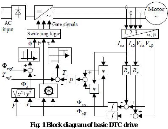
Fig. 1 Block diagram of basic DTC drive
Figure 1 shows the usual block diagram of a DTC controller. With DTC it is possible to obtain direct flux and electromagnetic torque control, indirect voltage and current control, sinusoidal current and flux, low torque ripple, superior torque dynamics and hysteresis band dependent inverter switching frequency [5], [2]. Among its main advantages is the absence of: coordinate transformation (which are usually necessary in most vector control drives), modulation specific block, and the absolute position determination. However, there are some problems during start up and at low speed values, like the difficulty in start up current control and high influence of the motor
The DTC scheme consists of torque and flux comparator (hysteresis controllers), torque and flux estimator and a switching table. It is much simpler than the vector control system due to the absence of coordinate transformation between stationary frame and synchronous frame and PI regulators. DTC does not need a pulse width modulator and a position encoder, which introduce delays and requires mechanical transducers respectively. DTC based drives are controlled in the manner of a closed loop system without using the current regulation loop. DTC scheme uses a stationary d-q reference frame having its d-axis aligned with the stator q-axis. Torque and flux are controlled by the stator voltage space vector defined in this reference frame [8]. The basic concept of DTC is to control directly both the stator flux linkage and electromagnetic torque of machine simultaneously by the selection of optimum inverter switching modes. The use of a switching table 1 for voltage vector selection provides fast torque response, low inverter switching frequency and low harmonic losses without the complex field orientation by restricting the flux and torque errors within respective flux and torque hysteresis bands with the optimum selection being made. The DTC controller consists of two hysteresis comparator (flux and torque) to select the switching voltage vector in order to maintain flux and torque between upper and lower limit.
DTC explained in this paper is closed loop drive. Here flux and torque measured from the induction motor using proper electrical transducer. Then flux and torque errors are found out by equation (1) and (2) [7].
dΨ=Ψref - Ψ ………. (1)
dte=tref - te ………... (2)
Using flux and torque comparator flux and torque command obtained respectively. From these commands, drive can know flux has to increase or decrease and torque has to increase, make constant or decrease. Then by finding field
angle, drive can find sector of flux linkage vector. After acquiring signals from flux comparator (dΨ), torque
comparator (dte) and flux-linkage vector section (α), control algorithm of DTC was developed means gate pulse
Table 1 :Switching Vector Table
III. FUZZY LOGIC CONTROLLER BASED DTC
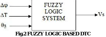
To obtain improved performance of the DTFC drive during changes in the reference torque, it is possible to use a fuzzy-logic-based switching vector selection process[1]. For this purpose a Mamdani-type fuzzy logic system will be used. The different output voltage states (active and zero states) are selected by using three inputs: flux e and torque errors and also the position of the stator flux linkage space vector us (Fig.2). Two mamdani type fuzzy logic controllers which contain fuzzifier, inference engine, rule base and defuzzifier replace the two hysteresis comparators in conventional DTC. Flux error fuzzification The flux error is obtained from equation (12) ΔΨ = Ψs* - Ψs (12) For flux
error, there are three linguistic terms negative error, zero error and positive error denoted as N, Z and P. For this purpose it is assumed that the stator flux link-age space vector can be located in any of twelve sectors, each spanning over a 60◦ wide region.
Fig.2 FUZZY LOGIC BASED DTC
For every sector there are 15 rules. The stator flux error has three fuzzy sets: stator error can be positive P, zero ZE, and negative N. For the torque error, there are five fuzzy sets: the torque error em = M∗m fMs can be positive large PL, positive small PS, zero ZE, negative small NS and negative large NL (Fig. 2). Since there are 12 sectors, for each sector 15 rules, the total number of rules is 180.
IV.PROPOSED FUZZY LOGIC CONTROLLER
The fuzzy logic control is one of the controllers in the artificial intelligence techniques. Fig.4 shows the schematic model of Fuzzy based DTC for IMD. In this project, Mamdani type FLC is used and the DTC of IMD using PI controller based SR(speed regulator) are requires the precise mathematical model of the system and appropriate gain values of PI controller to achieve high performance drive. Therefore, unexpected change in load conditions would produce overshoot, oscillation of the IMD speed, long settling time, high torque ripple, and high stator flux ripples. To overcome this problem, a fuzzy control rule look-up table is designed from the performance of torque response of the DTC of IMD. According to the torque error and change in torque error, the proportional gain values are adjusted on-line [8].
The fuzzy controller is characterized as follows:
ISSN (Print) : 2320 – 3765 ISSN (Online): 2278 – 8875
I
nternational
J
ournal of
A
dvanced
R
esearch in
E
lectrical,
E
lectronics and
I
nstrumentation
E
ngineering
(An ISO 3297: 2007 Certified Organization)
Vol. 5, Issue 3, March 2016
2) Fuzzification using continuous universe of discourse, 3) Implication using Mamdani's „min‟ operator,
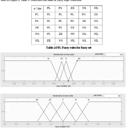
The membership functions of fuzzy logic controller flux-torque inputs and angle output can be Seen in Figure 3. Table 1. Describes rule table of fuzzy logic controller.
Figure 3. Flux, torque and angle membership functions
V. EXPERIMENTS
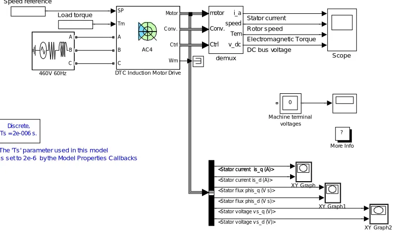
Simulations in Simulink/Matlab 6.5.1 verify the control. With a speed controller on the torque generator(Fig. 4& Fig5.) we get speed fuzzy DTFC control of the induction machine. For verification of the control we do not need the speed, torque and flux estimators (for sensorless control). These state values are the feedback from the model of the induction machine.
The 'Ts ' parameter used in this model is s et to 2e-6 by the Model Properties Callbacks
Discrete, Ts = 2e-006 s.
motor Conv. Ctrl i_a speed Tem v_dc demux XY Graph2 XY Graph1 XY Graph Speed reference Scope ? More Info 0
Machi ne termi nal vol tages
Load torque SP
Tm Motor Conv . Ctrl Wm A B C AC4
DT C Inducti on Motor Dri ve A
B
C
460V 60Hz
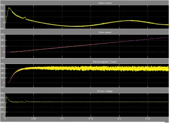
Stator current Rotor s peed Electrom agnetic Torque DC bus voltage
<Stator current is_q (A)> <Stator current is_q (A)>
<Stator current is_d (A)>
<Stator f lux phis_q (V s)>
<Stator f lux phis_d (V s)>
<Stator v oltage v s_q (V)>
<Stator v oltage v s_d (V)>
ISSN (Print) : 2320 – 3765 ISSN (Online): 2278 – 8875
I
nternational
J
ournal of
A
dvanced
R
esearch in
E
lectrical,
E
lectronics and
I
nstrumentation
E
ngineering
(An ISO 3297: 2007 Certified Organization)
Vol. 5, Issue 3, March 2016
Fig 4.2 SIMULINK model of DTC Switching Table using Fuzzy Controller.
VI. SIMULATION RESULTS
To study the performance of the proposed DTC with fuzzy logic controllers, simulation was carried out using MATLAB/SIMULINK simulation package.
VII. CONCULSION
By these simulations we have verified the control of zero speed operation, where the control is more sensitive than elsewhere. Figure 7 presents the curves of the switching state, for example only Sa So they kind of fuzzy torque control system for induction motor based on fuzzy control technique. On the basis of analyzing diagram of voltage vector, authors acquired whole fuzzy control rule set. The simulation results suggest that FLDTC of induction machine can achieve precise control of the stator flux and torque. Compared to conventional DTC, presented method is easily implemented, and the steady performances of ripples of both torque and flux are considerably improved. The main improvements shown are Reduction of torque and current ripples.
REFERENCES
[1] I. Takahashi and T. Noguchi, ″A New Quick-Responseand High-Efficiency Control Strategy of InductionMotor,″IEEE Trans. On IA, Vol.22, N°.5, Sept/Oct1986, PP.820-827.
[2] M. Depenbrock, ″Direct self – Control (DSC) of Inverter– Fed Induction Machine,″IEEE Trans. PowerElectronics, Vol.3, N°.4, Oct 1988, PP.420-829.
[3] D.Casadei, F.Profumo, G.Serra and A.Tani, ″FOC andDTC:Tox Viable Schemes for Induction Motors TorqueControl,″IEEE Trans. Power Electronics. On PE,Vol.17, N°.5, Sept2002,
[4] D.Casadei and G.Serra, ″Implementation of DirectTorque Control Algorithme for Induction Motors Basedon Discrete Space Vector Modulation,″ IEEE Trans.Power Electronics, Vol.15, N°.4, JULY2002.
[5] A.A.Pujol, Improuvment in Direct Torque Control ofInduction Motors, Thèse de doctorat de L’UPC,Novembre2000
[6] Y.Xia W.Oghanna " Study on Fuzzy Control ofInduction Machine With Direct Torque ControlApproach " ,IEEE Catalog Number: 97TH8280- ISIE'97- GuimarBes, Portugal
[7] Mir, S., Elbuluk, M.E., Zinger, D.S., PI and fuzzy estimators for tuning the stator resistance in direct torque control of induction machines, IEEE Trans. Power Electron. 1998. – Vol.13 – P. 279–287.
[8] Arias, A., Romeral, J.L., Aldabas, E., Jayne, M.G., Fuzzy logic direct torque control, IEEE International Symposium on Industrial Electronics (ISIE), 2000. – Vol.1 – P. 253–258.
[9] Holtz, J., Quan, J., Sensorless vector control of induction motors at very low speed using a nonlinear inverter model and parameter identification, IEEE Trans. Ind. Appl., 2002. Vol. 38 – No. 4 – P. 1087–1095.
[10] Casadei, D., Serra, G., Tani, A., Zarri, L., Profumo, F., Performance analysis of a speed-sensorless induction motor drive based on a constant switching-frequency DTC method, IEEE Trans. Ind. Appl.2003. – Vol. 39 – No. 2 – P. 476–484.
[11] Kaboli, S., Zolghadri, M.R., Haghbin, S.,Emadi, A., “Torque ripple minimization in DTC of induction motor based on optimized flux value determination,” IEEE Ind. Electron. Conf., 2003, pp. 431–435.
[12] Kioskeridis, I., Margaris, N., “Loss minimization in induction motor adjustable speed drives,” IEEE Trans. Ind. Electron., 1996, vol. 43, no. 1, pp. 226–231.