Papers presented in ICRRTET Conference can be accessed from
http://edupediapublications.org/journals/index.php/IJR/issue/archive
P a g e
|
479
The Floating Solar Chimney Technology
Namita P. Deodhe
1& Srujan G. Raut
2Department of Electrical Engineering
Dr. Babasaheb Ambedkar Technological University, Lonere – 402 103
1[email protected];
2[email protected]
Abstract
-
Electricity generation is major co
2producer. We
should notice that electricity can replace as the
energy
activities
related
to
fossil
fuel
technologies. Thus a solution to the global
warming is possible if we succeed to generate
zero emission clean electricity. The renewable
electricity generating technologies is major tool
towards the aim of eliminating the greenhouse
emission and will save our planet. Hence we are
presenting the “FLOATING SOLAR CHIMNEY
TECHNOLOGY (FSC)”. This technology is
advisable one for large scale solar electricity
generating especially in desert or semi desert
areas and major technology is for global warming
elimination.
This paper is tool to harness some part of
solar energy for power generation. Due to
greenhouse effect, the air is warmed in solar
collector .The warm air is moving from the
periphery of solar collector to its centre of the
chimney. This moving stream of warm air leaves
part of its thermodynamic energy to air turbines
that are geared with electric generators. It can
operate 24 hours per day and 365 days per year
eliminating the co
2emission and reducing global
warming mainly in the desert and semi-desert
areas.
Future scope for this floating solar
chimney technology is in the production of
hydrogen by electrolysis process in very low cost.
Also it can be used for sea-water desalination by
using a condenser with floating solar chimney
technology. This technology could supply cheap
and clean electricity and hydrogen securing the
world economic development and leading to a
safer
and
less
tensioned
sociopolitical
environment. That is why we can say that Floating
Solar Chimneys is the link towards a solar future.
It is having low cost consumption of fossil fuels.
There is no ecological harm and no consumption
of resources and it will be beneficial for the
developing countries.
Keywords- Greenhouse effect; solar chimney;
solar collector; air turbines; electric generator a
floating solar chimney power station.
I. INTRODUCTION
The purpose of this chapter is to present
the Floating solar chimney (FSC) technology is to
use solar energy for generation of electricity and to
reduce the global warming. This technology is the
advisable one for candidacy for large scale solar
electricity generation especially in desert or semi
desert areas of our planet and a major technology
for the global warming elimination. The solar
chimney power plants are usually referred to as
solar
updraft
towers
Papers presented in ICRRTET Conference can be accessed from
http://edupediapublications.org/journals/index.php/IJR/issue/archive
P a g e
|
480
Also the solar updraft technology is far
more expensive compared to the conventional
fossil fueled power plants of similar electricity
generation. That is why the solar chimney
technology has not yet been applied although it is a
solar technology of many advantages.
FSC technology is cost effective to be split
into small units of several MW each. The Floating
Solar Chimney Power Plant, named by the author
as
Solar Aero-Electric Power Plant (SAEP)
due
to its similarity to the Hydro-Electric power plant,
is a set of three
major components:
•
The Solar Collector
. It is a large
greenhouse open around its periphery with
transparent roof supported a few meters above the
ground.
•
The Floating Solar Chimney (FSC)
. It is
a tall fabric cylinder placed at the centre of the
solar collector through which the warm air of the
greenhouse, due to its relative buoyancy to the
ambient air, is up-drafting.
•
The Turbo-Generators
. It is a set of air
turbines geared to appropriate electric generators in
the path of up-drafting warm air flow that are
forced to rotate generating electricity. The gear
boxes are adjusting the rotation speed of the air
turbines to the generator rotation speed defined by
the grid frequency and their pole pairs.
Fig.01: Solar chimney
The big height H of the solar chimney is necessary, because the efficiency of its respective power station is proportional to H. The efficiency of the solar power station is defined as the „ratio of the power produced annually by electric energy to the annual solar energy arriving on the surface area of its solar collector‟. Power plants with very tall concrete solar chimneys are called “Solar Towers”.
II.
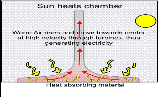
FUNCTIONAL PRINCIPLE
The principle is shown in fig 2: Air is heated by solar radiation under a low circular translucent roof open at the periphery; the natural ground below it form an air collector. In the middle of the roof and the natural ground below it form an air collector. In the middle of the roof is a vertical tower with large air inlets at its base. The joint between the roof and the tower base is airtight. As hot air is lighter than cold air it rises up the tower. Suction from the tower then draws in more hot air from the collector, and cold air comes in from the outer perimeter. Continuous 24 hours-operation can be achieved by placing tight water filled tubes or bags under the roof. The water heats up during day time and releases its heat at night. These tubes are filled only at once, no further water is needed. Thus solar radiation causes a constant updraft in the tower. The energy contained in the updraft is converted into mechanical energy by pressure-staged turbines at the base of the tower, and into electrical
Papers presented in ICRRTET Conference can be accessed from
http://edupediapublications.org/journals/index.php/IJR/issue/archive
P a g e
|
481
Fig .02 : Operating principle
III. CONSTRUCTION
Major parts of floating solar chimney are as follows: 1. The solar collector (Greenhouse)
2. Air drafting Cylinder on the centre of this Greenhouse 3. A set of Air Turbines
4. The electric generators 5. The gear box
1. THE SOLAR COLLECTOR
The solar collector can be an ordinary circular greenhouse with a double glazing transparent roof supported a few meters above the ground. The periphery of the circular greenhouse should be open to the ambient air. The outer height of the greenhouse should be at least 2 meters tall in order to permit the entrance of maintenance personnel inside the greenhouse. The height of the solar collector should be increased as we approach its centre where the FSC is placed. As a general rule the height of the transparent roof should be inversely proportional to the local diameter of the circular solar collector in order to keep relatively constant the moving air speed. The circular greenhouse periphery open surface can be equal or bigger than the FSC cut area.
Another proposal with a simpler structure and shape the greenhouse can be of a rectangular shape of side DD. The transparent roof could be made of four equal triangular transparent roofs, elevating from their open sides towards the centre of the rectangle, where the FSC is placed. Thus the greenhouse forms a rectangular pyramid.
In desert application of the FSC technology the solar collectors are used exclusively for air warming. Also in desert or semi desert areas the dust on top of the transparent roofs of the conventional greenhouses could be a major
problem. The dust can deteriorate the transparency of the upper glazing and furthermore can add unpredictable weight burden on the roof structure. The cleaning of the roof with water or air is a difficult task that can eliminate the desert potential of the FSC technology. Furthermore in desert or semi-desert areas the construction cost of the conventional solar collector (a conventional greenhouse) could be unpredictably expensive due to the unfavorable working conditions on desert sites.
For all above reasons another patented design of the solar collectors has been proposed by the author. The proposed modular solar collector, as has been named by the author, will be evident by its description that it is a low cost alternative solar collector of the circular or rectangular conventional greenhouse which can minimize the works of its construction and maintenance cost on site.
We can also use and follow the ground elevation on site, and put the FSC on the upper part of the land-field therefore the works on site for initial land preparation will be minimized.
The greenhouse will be constructed as a set of parallel reverse-V transparent tunnels made of glass panels as shown in the next figure. The maximum height of the air tunnel should be at least 190cm in order to facilitate the necessary works inside the tunnel, as it is for example the hanging of the inner crystal clear curtains.
2. FLOATING SOLAR CHIMNEY
In order to increase the efficiencies of the solar chimney power stations we need solar chimneys of even higher heights.
The forces acting on the FSC are basically two:
• The sub-pressure forces. The forces which are resulted from the static pressure difference between the warm stream of air inside the FSC and the air on its exterior.
• The forces from the external winds, which are appeared at the places where the FSC is installed.
Papers presented in ICRRTET Conference can be accessed from
http://edupediapublications.org/journals/index.php/IJR/issue/archive
P a g e
|
482
Fig.03: Inner diameter
To encounter external wind‟s forces is a rather more complicated issue. To do so the supporting rings are not sufficient, although they do help in this respect. The external winds‟ problem is encountered by the FSC‟s deflecting ability.
Thus when external winds appear the FSC is deflecting, reaching its angle of balance (figure 4 and 5). In this way, in its balance position, the FSC encounters vertically only the drag forces from the velocity‟s normal components, which are counter-balanced from the opposite FSC‟s buoyancy components. These normal forces to the FSC‟s cylinder are encountered locally with the assistance of the supporting rings. Wind velocity‟s tangent component creates a friction force parallel to the FSC‟s cylinder without deforming its shape.
As already stated in order to encounter the winds‟ action on the FSC, it should have a deflecting ability. For this purpose two more elements are necessary:
A system that will keep the FSC at its position and which will receive the parallel and tangent forces from the external winds. This system is a two-part heavy base, which can incline on the FSC‟s seat without parting from it. (Fig.: 4).
A flexible (accordion type) folding part of its base which will be unfolded partly as a result of the deflection, preventing the warm air to escape by the bottom of the structure (fig.:5). The FSC construction is made by a series of balloon-rings from light enduring (airship) fabric connected successively in such a way that they form the main cylinder of the solar chimney.
Fig.:04 Fig.:05
This wind‟s velocity variation creates differential forces along the chimney‟s cylinder. To encounter these differential forces the chimney‟s cylinder is separated in parts. These parts are constructed by a fixed number of tube balloon-rings. The parts are separated by isolation tubes filled with environment‟s air, which can easily get in and out of them.
These relief tubes isolate dynamically the consecutive parts of FSC from each other, allowing each part to reach its own deflecting angle, depending on the average wind velocity on the altitude where it is located.
3. AIR TURBINES
The air turbines of the SAEPs are either of horizontal axis placed in a circular pattern around their FSCs or with normal axis placed inside the FSCs (near the bottom). The latter case with only one air turbine is most appropriate for the FSC technology, while the former is more advisable for concrete solar chimney technology applications. The air turbines of the solar chimney technology are caged (or ducted) air turbines. These air turbines are not similar to wind turbines that transform the air kinetic energy to rotational energy; therefore their rotational power output depends on the wind speed or the air mass flow. The caged air turbines transform the dynamic energy of the warm air, due to their buoyancy, to rotational. Therefore their rotational power output does not depend on the mass flow only but on the product of the mass flow and the pressure drop on the air turbine.
Therefore the warm air mass flow, as we have noticed already, is possible to remain approximately constant during the daily operation (in order that an optimal operation is achieved while its rotational power and its relative electric power output vary during the daily cycle. The varying quantity is the pressure drop of the air turbine. This pressure drop depends on the warm air temperature i.e. the warm air proportional buoyancy and the FSC height. The air turbines are classified according to the relation between their mass flows and their pressure drops.
Generally the air turbines are classified according to the relation between their mass flows and their pressure drops. They are classified as follows:
1. CLASS A 2. CLASS B 3. CLASS C
1. CLASS A
They have large mass flow. They have small pressure drop. .
2. CLASS B
They are caged air turbines. They have lower pressure drop. They have higher mass flow. They are made without inlet guiding vanes.
3. CLASS C
Papers presented in ICRRTET Conference can be accessed from
http://edupediapublications.org/journals/index.php/IJR/issue/archive
P a g e
|
483
4. THE ELECRIC GENERATOR
There are two types or electric generators which can be used in SAEPs, the synchronous and the induction or asynchronous electric generators. The synchronous electric generators for FSC technology should have a large number of pole pairs (pp). The frequency of the generated electricity by the multi-pole synchronous electric generator should be equal to the grid frequency f. The generated electricity frequency of the synchronous generators fel is
proportional to its rotational frequency. Thus in case of varying fe an
electronic drive is necessary, for adjusting the generated electric frequency to the grid electric frequency f. A multi-pole (high value of pp) synchronous electric generator combined with an electronic drive can be a reasonable solution in order to avoid the adjusting gear box.
In order to control the set to operate the whole SAEP under optimal conditions we either control its electronic drive unit or its air turbine blade pitch. The induction generators are of two types. The squirrel cage and the double fed or wound rotor induction generators. The squirrel cage induction generators rotate with frequencies close to their synchronous respective frequencies f/pp defined by the grid frequency and their pairs. For given pole-pairs (for example for four pole caged induction generators pp=2) the induction generator should engage itself to the air turbine through an appropriate gear box that is multiplying its rotational frequency in order that the generator rotational speed matches to the frequency (f/pp)·(1+s), where s is the absolute value of the slip and it is a small quantity in the range of 0.01 for large generators. The electric power output of the squirrel cage induction generator is approximately proportional to the absolute value of the slip s near their operating point. Thus even high power variations can be absorbed with small rotational frequency variations. Therefore the squirrel cage induction generators engaged to the air turbines with proper gear boxes are supplying the grid always with the proper electric frequency and voltage without any electronic control. The only disadvantage of the squirrel cage induction generators is that they always produce an inductive reactive power. This reactive power should be compensated using a parallel set of capacitors creating a capacitive reactive power.
5. THE GEAR BOX
The gear box is a essential device for adjusting the frequency of the rotation of the air turbines fT to the electric
frequency f of the grid through the relation,
(1)
The rt is the rate of transmission of the gear box i.e. the generator
rotates with frequency.
When conventional electric generators with a few pole pairs (low pp) are used, as electricity generating units, gear boxes with a proper rate of transmission rt are necessary. However if
multi-pole electric generators are used with high pole-pair values (pph) then the gear boxes can be avoided (if ). The gear boxes are mechanical devices made of gears of various
diameters and combinations in order to transform their mechanical rotation incoming and out-coming characteristic by the relation,
The gears demand a continuous oil supply and have a limited life cycle. Thus the gear boxes being huge and heavy devices of high maintenance and sensitivity, if possible they should not be preferred.
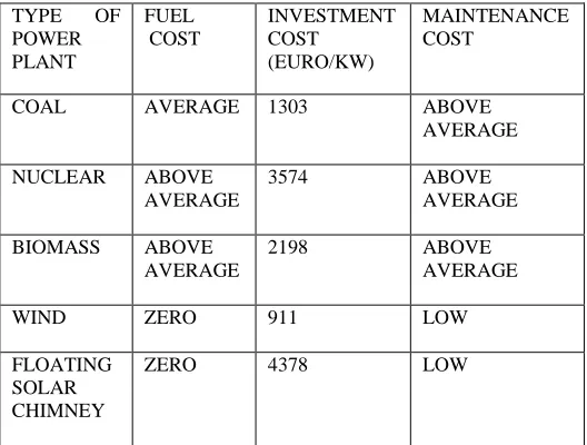
IV. COMPARISON WITH OTHER POWER STATION
TABLE 1: COMPARISON WITH OTHER POWER PLANTS
TYPE OF POWER PLANT
FUEL COST
INVESTMENT COST
(EURO/KW)
MAINTENANCE COST
COAL AVERAGE 1303 ABOVE AVERAGE
NUCLEAR ABOVE AVERAGE
3574 ABOVE AVERAGE
BIOMASS ABOVE AVERAGE
2198 ABOVE AVERAGE
WIND ZERO 911 LOW
FLOATING SOLAR CHIMNEY
ZERO 4378 LOW
V. OUTPUT OF FLOATING SOLAR CHIMNEY
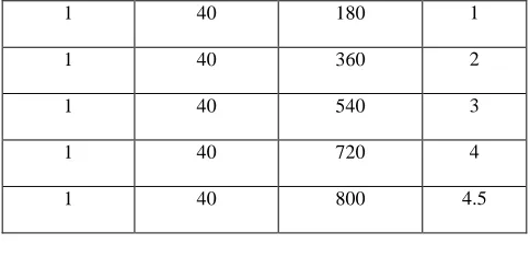
Mainly the output of the floating solar chimney power plant depends upon the height, inner diameter of chimney and area of solar collector.
1. Effect of change in height of FSC
TABLE 2. : VARIATION OF OUTPUT W.R.T. CHANGE IN HEIGHT
Solar collector area in Km2
FSC internal diameter d in m
FSC height H in m
Papers presented in ICRRTET Conference can be accessed from
http://edupediapublications.org/journals/index.php/IJR/issue/archive
P a g e
|
484
1 40 180 1
1 40 360 2
1 40 540 3
1 40 720 4
1 40 800 4.5
2. Effect of change in solar collector area of FSC
TABLE 3. : VARIATION OF OUTPUT W.R.T. CHANGE IN INTERNAL DIAMETER
Solar collector area in Km2
FSC
internal diameter d in m
FSC height H in m
Rating power Pr in MW
0.25 36 720 1.0
0.50 36 720 2.0
0.75 36 720 3.0
1.0 36 720 4.0
VI. ADVANTAGES AND DISADVANTAGES
1. ADVANTAGES:
1. Solar chimney power stations are particularly suitable for generating electricity in deserts and sun-rich wasteland.
2. It provides electricity 24 hour a day from solar energy alone.
3. No fuel is needed. It needs no cooling water and is suitable in extreme drying regions.
4. The materials concrete, glass and steel necessary for the building of solar chimney power stations are everywhere in sufficient quantities.
5. No ecological harm and no consumption of resources.
2. DISADVANTAGES:
1. Floating solar chimneys have a very high capital cost .
2. The structure itself is massive and requires a lot of engineering expertise and materials to construct .
VII. FUTURE SCOPE
1. Hydrogen Production:
Doubly Fed Induction Generators(DFIG) or Synchronous generators (SG) should be used appropriately controlled in order to supply a constant voltage output that is necessary for the electrolysis production units. Their frequency variation does not have any effect on the electrolysis procedure because between the AC electric generators and the electrolysis‟s unit, an AC to DC converter is inserted, accompanied by an appropriate transformer. The supplied DC current to the electrolysis‟ units is producing proportional quantities of Hydrogen, and oxygen as a by-product.
Theoretically for electrolysis taking place in an
environment of 25oC and Po=101.300 Pa, 2gr H2 (1 moll) and 16 gr O (0.5 moll) can be produced by 18 gr H2O (water) with 237, 1 KJ of Electric energy and 48,7 KJ of thermal energy. Thus theoretically by electrolysis we produce 1 kg or H2 by ~142 MJ of electric energy (HHV) or by ~ 120 MJ (LHV) ( if 22 MJ thermal energy is offered by the environment). The electrolysis technology today can produce 1kg H2 by 158 MJ of electric energy (I.e. by 43.7 KWh), without the compression energy for H2. As a main byproduct, oxygen of 8 kg is produced simultaneously with a quantity of Heavy Water.
2. Combined solar chimney system for power generation and seawater desalination:
It is an alternative method of heat and moisture extraction from seawater under the collector of a solar chimney system for power generation and seawater desalination is investigated using
one-dimensional compressible flow model. Water and energy are
two inseparable items in our lives in recent years; both energy crisis and freshwater shortage problem posing great threat to the humans are attracting great importance around the world owing to rapid development of global economy, fresh water pollution, Increase in population, and improvement of living standards, Seawater desalination is one of the prevalent methods of obtaining large amounts of fresh water. The power generation–seawater desalination coupling scheme is very suitable for regions adjacent to the sea or natural alkaline lakes. The combined system consists of four components, i.e. the solar collector, the solar chimney, the turbine generators, and the high-efficiency condenser.
VIII. CONCLUSION
Papers presented in ICRRTET Conference can be accessed from
http://edupediapublications.org/journals/index.php/IJR/issue/archive
P a g e
|
485
REFERENCES
[1] Schlaigh J. 1995, “The Solar Chimney : Electricity from the sun” Axel Menges Edition, Stuttgart.Topic: Solar Chimneys
[2] Cannon A. , Von Backstrom T 2000, “Solar Chimney Cycle Analysis with System loss and solar
Collector Performance”, Journal of Solar Energy Engineering, August Vol 122/pp.133-137.Topic: Thermodynamic Cycle Analysis of the Solar Chimney Power Plants
[3] Von Backstrom T, Cannon A. 2000, “Compressible Flow Through Solar Power Plant Chimneys”. August vol 122/ pp.138-145. Topic: Study of Solar Chimneys with Variable Diameter
[4] Papageorgiou C. 2004 “Solar Turbine Power Stations with Floating Solar Chimneys”. IASTED. Proceedings of Power and Energy Systems, EuroPES 2004, Conference, Rhodes Greece July2004 pp, 151-158 Topic: Theoretical Performance Analysis of Floating Solar Chimney Power Stations.
[5] Papageorgiou C. 2004, “External Wind Effects on Floating Solar Chimney” IASTED Proceedings of Power and Energy Systems, EuroPES 2004, Conference, Rhodes Greece ,July 2004 2004 pp.159-163 Topic: External Wind Effects on the Floating Solar Chimneys.
[6] Papageorgiou C. 2004, “Optimum Design for Solar Power Stations with Floating Solar Chimneys‟‟, proceedings of ISES Asia Pacific Solar Energy Conference, Kwangju Korea, October 2004 pp.763-772. Topic: Design, Calculations and Cost of Floating Solar Chimneys and their respective Power Plants .
[7] Papageorgiou C. 2004, “Efficiency of solar air turbine power stations with floating solar chimneys‟‟ IASTED Proceedings of Power and Energy Systems Conference Tampa Florida USA, November 2004, pp. 127-134.
Topic: Efficiency and Annual Performance of Floating Solar Chimney Power Stations
[8] Papageorgiou C. 2005 “Turbines and Generators for Floating Solar Chimney Power Stations”.
IASTED Proceedings of Power and Energy Systems, EuroPES 2005 conference. Benalmadena
Spain June 2005,pp.73-80.
Topic: Operation of Floating Solar Chimney Power Stations taking into consideration its AirTurbines and Electric Generators Performances.
[9] Papageorgiou C. 2005 “Hydrogen Production by Solar Aero Electric Power Plants with Floating Solar Chimneys» International Hydrogen Energy Congress Conference 2005,Istanbul Turkey, July 2005
Topic: Evaluation of Hydrogen Production units composed of Solar Aero Electric Power Plants with Floating Solar Chimneys and appropriate Electrolysis Units.
[10] Papageorgiou C. 2005 “Floating Solar Chimney: The Link towards a Solar Future” ISES 2005 Solar World Congress Conference, Orlando Florida USA, August 2005. Topic: Cost of Solar Aero Electric Power Plants with Floating Solar Chimneys of variable Height and their comparison to Conventional Power Plants.
[11] Papageorgiou C. 2006 “Floating Solar Chimney Power Stations with Thermal Storage”. IASTED proceedings of Power and Energy Systems, EuroPES 2006. Rhodes Greece July 2006( to be presented).