A 5.8-GHz Planar Beam Tracking Antenna Using a Magic-T
Rimi Rashid*, Eisuke Nishiyama and Ichihiko Toyoda
Abstract—This paper proposes a novel planar beam tracking antenna and brings a new prototype antenna in wireless communication systems. The proposed antenna consists of a magic-T, two antenna elements and two phase shifters. The main idea for the antenna is to adjust the phase shifter using the difference of the signals received by the two antenna elements to tilt the beam in the direction of the arrival wave. Theoretical discussion is presented to explain the concept. Both-sided MIC technology is effectively used to integrate the magic-T and the phase shifters with the antenna elements in a simple structure. A prototype antenna of the new design for E-plane beam tracking is fabricated, and the radiation pattern and return loss are measured. Simulated and experimental results of the beam direction vs. applied voltage are successfully compared, and the proposed concept is experimentally demonstrated. An antenna structure for beam tracking inH-plane is also demonstrated in this paper.
1. INTRODUCTION
A wide range of wireless technologies is currently used in wireless communication systems. Advanced technologies based on digital signal processing have been developed to fulfill the requirements of higher data rate, larger capacity and higher efficiency. Accordingly, multifunction and high performance microwave and millimeter wave components are also required to promote the wireless technologies [1].
Development of advanced planar antennas based on RF signal processing is a revolution in the field of the wireless communication technology. These new generation antennas provide many important features such as low profile, light weight, low cost and ease of integration into arrays. These features make them ideal components for radars and modern communication systems, especially, for portable wireless devices. Properties of planar antennas have been discussed many times in many journals and proceedings [2, 3]. The radiation properties of the planar antennas were also investigated by using photonic crystal as substrate material [4]. Several types of advanced planar antennas have been developed for the RF signal processing [5]. These antennas are constructed with microstrip lines and slot lines on both sides of the substrate and microwave circuits such as a magic-T are integrated with antenna elements [6]. A direction of arrival estimation antenna [7–9] and beam steering antenna [10] are already presented.
Several research works have been done to enhance the evolution of beam tracking systems in wireless communications. Many tracking systems, i.e., manual/programmed steering, monopulse tracking, sequential amplitude sensing tracking (conical scan and step track) and electronic beam squinting are developed. A planar antenna for the beam tracking system was proposed for land vehicle satellite communications. A step back method by using an angular rate sensor is used in this system [11]. Another tracking phased array antenna system for the shipboard station in X-band satellite communications was described. This antenna has TX and RX antenna beams as well as a tracking beam where the beams are independently steered electronically in elevation and mechanically in azimuth [12].
Received 25 April 2017, Accepted 24 July 2017, Scheduled 5 August 2017 * Corresponding author: Rimi Rashid ([email protected]).
We have also presented a planar 10-GHz beam tracking antenna using a magic-T applying monopulse tracking mechanism [13]. The main function of beam tracking antennas is shifting their beam according to the received waves. The beam tracking antenna that we have proposed is also a novel antenna in the RF signal processing. The antenna was designed, fabricated and also measured experimentally.
In this paper, a novel 5.8-GHz planar beam tracking antenna is proposed. The advantage of the proposed antenna over digital processing beam tracking is low power consumption and rapid response due to the analog processing of the system. The concept and basic operation principle of the beam tracking antenna are discussed with theoretical calculations in Section 2. In Section 3, the structure and design of the antenna which integrates antenna elements and microwave circuits such as a magic-T and phase shifter are described. These microwave circuits are also briefly introduced in this section. Section 4 shows a prototype beam tracking antenna designed at the 5.8-GHz band for E-plane beam tracking. The measured results which demonstrate the concept of the proposed beam tracking antenna and the comparison between simulation and experimental results are also highlighted in this section. An H-plane beam tracking structure is newly proposed and demonstrated in Section 5. Finally, Section 6 concludes the paper.
2. BEAM TRACKING PRINCIPLE 2.1. Configuration
Figure 1 illustrates the basic block diagram of the proposed beam tracking concept. The proposed beam tracking antenna consists of two antennas, a magic-T and a phase shifter. A detector and controller circuit are attached to the proposed antenna to adjust the phase shifter. The phase shifter is used to change the phase of the signal received by one of the two antenna elements. By changing the phase shift value of the phase shifter to compensate the phase difference, maximum power is obtained by combining the two received signals. It describes that the beam of the antenna array shifts in the direction of the arrival wave. In the proposed antenna, a magic-T is employed to combine the two received signals and detect the phase difference of the signals received by the two antennas. As a magic-T is a microwave circuit that provides in-phase or anti-phase power division according to the input and output ports, the sum (Σ) and difference (Δ) of the received signals are easily obtained by using the magic-T.
Arrival wave
Magic-T Phase Shifter
ϕ0
Detector & Controller Circuit
Receiver Σ
Δ
Figure 1. Block diagram of the proposed beam tracking concept. A magic-T generates the sum (Σ) and difference (Δ) of the signals received by two antennas. The Δ signal is used to control the phase shifter.
2.2. Operating Principle
relation of the arrival angle θ and phase differenceϕis expressed in
ϕ= 2πd
λ sinθ (1)
where d and λ are the antenna separation and wavelength, respectively. Hence, the sum (Σ) and difference (Δ) of the received signals are expressed in the following expressions:
Σ = D(θ)ejϕ2e−jϕ0 +D(θ)e−jϕ2
= 2D(θ)e−jϕ20 cos
ϕ−ϕ0 2
(2)
Δ = D(θ)ejϕ2e−jϕ0 −D(θ)e−jϕ2
= 2jD(θ)e−jϕ20 sin
ϕ−ϕ0
2
(3)
where ϕ0 and D(θ) are the phase shift value of the phase shifter and the radiation pattern of a single antenna element, respectively.
ϕ=ϕ1-ϕ2 ϕ1
d
dsinθ Arrival wave
θ
ϕ2
ϕ0
#1 #2
#2 #1
Δ
Re Im
ϕ−ϕ0 Σ
(a) (b)
Figure 2. Operating principle of the proposed beam tracking antenna. (a) Received signals. (b) Vector diagram.
The main objective of this antenna is to shift the main beam direction according to the arrival wave, i.e., make the Σ maximum. Figure 2(b) illustrates the relation among two received signals, their sum (Σ) and difference (Δ) with a vector diagram. As shown in this figure and above expressions, Σ becomes maximum, and Δ becomes zero whenϕ0=ϕ. It means that the beam tilts in the direction of the arrival wave by adjusting the phase shifter to make the Δ minimum.
2.3. Theoretical Result
Figure 3 shows the theoretical results of the radiation pattern of Σ and Δ signals calculated using Eqs. (2) and (3) for the phase shiftϕ0 = 0◦, 30◦, 60◦ and 90◦. D(θ) is also plotted as a reference. Here, the radiation pattern of a single rectangular patch antenna is used forD(θ), which is expressed by the following expression [14]:
D(θ) = cos
βL
2 sinθ
(4)
-40 -30 -20 -10 0
Relative Power [dB]
-90 -60 -30 0 30 60 90
Angleθ [deg.]
D(θ)
ϕ0 = 0
o
ϕ0 = 30
o
ϕ0 = 60o
ϕ0 = 90o
-40 -30 -20 -10 0
Relative Power [dB]
-90 -60 -30 0 30 60 90
Angleθ [deg.]
D(θ)
ϕ0 = 0o
ϕ0 = 30o
ϕ0 = 60o
ϕ0 = 90o
(a) (b)
Figure 3. Theoretical radiation patterns of Σ and Δ signals. The main beam of the Σ and null of the Δ shift to right according to the phase shift value ϕ0. The radiation pattern of a single rectangular patch antenna is D(θ) also plotted as a reference. (a) Σ signal. (b) Δ signal.
3. BEAM TRACKING ANTENNA DESIGN 3.1. Antenna Design
Figure 4 shows the structure of the proposed beam tracking antenna. Two microstrip antennas, a magic-T and two phase shifters are integrated on a substrate. Capacitors (9 pF) are used for DC cut. In this design, two phase shifters are used to tilt the beam to both directions. The magic-T and phase shifters effectively employ the both-sided MIC technology [6]. The input impedance of each antenna element is designed to be 100 Ω, and it is converted to the port impedances of 50 Ω using the magic-T and a quarter-wavelength impedance transformer. Biasing circuits used in the 10-GHz beam tracking antenna [13] are omitted in this 5.8-GHz antenna structure. The bias voltage of each phase shifter is applied via a probe at the center of the patch to change the phase shift value.
Phase Shifter
A A' Port 1
Microstrip Line
Slot Line Port 2
Bias Probe Magic-T
Σ
Δ
Varactor Diode Capacitor
A A'
x
x y
z
θ
y z
Microstrip Antenna
Impedance Transformer
3.2. Magic-T
Recently, integrated magic-T structures have been widely used in microwave circuits and systems. The magic-Ts are four-port devices that offer in-phase and anti-phase signal division between their two output ports [15, 16].
Figure 5 shows the basic structure of the magic-T used in the proposed antenna and its equivalent circuit. The magic-T is a combination of a microstrip line T junction and a slot-to-microstrip line T branch. The impedance of Port M1 is half of the impedance of Ports M3 and M4. On the other hand, the impedance of Port M2 is the double of the impedance of Ports M3 and M4. The signals fed from Ports M3 and M4 with the same phase are combined, and the combined signal emerges at Port M1, as the microstrip line T junction is a parallel branch. On the other hand, as the slot-to-microstrip line T branch is a series branch, the signals fed from Ports M3 and M4 with anti-phase are combined, and the combined signal emerges at Port M2. Ports M1 and M2 are isolated due to the difference of the propagation modes of the microstrip line and slot line.
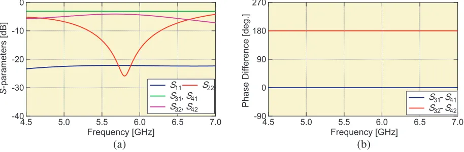
Figure 6 shows the simulated performance of the magic-T. As shown in Figure 6(a), the return losses of Ports M1 and M2 are better than 20 dB at 5.8 GHz, while the insertion losses of the in-phase signal (S31, S41) and anti-phase signal (S32, S42) are less than 3.1 dB and 4.1 dB, respectively. The isolations (S34, S12) are better than −19.9 dB and −84.1 dB. Extremely high isolation between Ports M1 and M2 is achieved. Figure 6(b) shows the phase difference vs. frequency plot, which confirms that the magic-T provides in-phase and anti-phase power division. Then, when RF signals are fed from
Microstrip Line
Slot Line Port M2
Port M4 Port M1
Port M3 Port M3
(Z0)
Port M1 (Z0/2)
Port M4 (Z0)
Port M2 (2Z0)
Slot Line
Anti-Phase Signal
In-Phase Signal Microstrip Line
(a) (b)
Figure 5. Structure and equivalent circuit of the T used in the proposed antenna. The magic-T is constructed with a microstrip line magic-T junction and slot-to-microstrip line magic-T branch. Sum and difference of the signals fed to Port M3 and M4 emerge at Port M1 and M2, respectively. (a) Structure. (b) Equivalent circuit.
-40 -30 -20 -10 0
S
-parameters [dB]
7.0 6.5
6.0 5.5
5.0 4.5
Frequency [GHz]
S11 S22 S31, S41 S32, S42
270
180
90
0
-90
Phase Difference [deg.]
7.0 6.5
6.0 5.5
5.0 4.5
Frequency [GHz]
S31-S41 S32-S42
(a) (b)
Ports M3 and M4, the sum and difference of the signals are separately obtained at Ports M1 and M2, respectively. However, the sum (Σ) and difference (Δ) of the received signals are respectively obtained at Port 1 and Port 2 in Figure 4 because the two microstrip antennas are fed from the opposite sides of the patches. The simulation is performed by Keysight Technologies’ ADS simulation software.
3.3. Phase Shifter
Figure 7 shows the structure of the phase shifter which consists of a de Ronde’s coupler [17] and varactor diodes. The de Ronde’s coupler is constructed with a microstrip line and slot line, and it provides a π/2 hybrid function with a simple structure. Two varactor diodes are attached to Ports R2 and R4 of the coupler, and the phase shift is obtained by changing the bias voltage of the varactor diodes. The signal received from the antenna element is applied to Port R1 as input, and the output of the phase shifter is received from Port R3 in different phases by applying different bias voltages. Hence, the beam directionθ changes by changing the bias voltage.
Microstrip Line Slot Line
A' A' Port R1
Port R4
Varactor Diode
A A
Port R2
Port R3
Figure 7. Structure of the phase shifter. The phase shifter consists of a de Ronde’s coupler and varactor diodes.
Figure 8 shows the measured performance of the phase shifter. The reflection coefficients of the phase shifter are below the 10-dB level for every bias voltage as shown in Figure 8(a) where the bias voltage is applied to the varactor diodes via a bias-T. It is also confirmed from Figure 8(b) that the insertion losses are near 1.5 dB at the design frequency 5.8 GHz. Both results ensure the performance of the designed phase shifter very well.
-30 -20 -10 0
Reflection Coefficient [dB]
7.0 6.5
6.0 5.5
5.0 4.5
Frequency [GHz] S11: 1 V 5 V 9 V S22: 1 V 5 V 9 V
-20 -15 -10 -5 0
Transmission Coefficient [dB]
7.0 6.5
6.0 5.5
5.0 4.5
Frequency [GHz] S21: 1 V 5 V 9 V
(a) (b)
Figure 9 shows the relation between the phase shift value ϕ0 and applied voltage of a prototype phase shifter. The red line indicates the simulated result, and the blue line shows the measured result. In the simulation process, the relation between the phase shift value ϕ0 and the applied voltage is calculated by Keysight Technologies’ ADS simulation software. For this simulation purpose, capacitors are used instead of the varactor diodes. The value of the capacitor is tuned from 2 pF to 0.225 pF which is equivalent to 1 V to 10 V (calculated by the data sheet of the varactor diode (MA46580)). Thus the phase shift value ϕ0 can be obtained with respect to its applied bias voltage. The value of the beam directions can be calculated by using Eq. (1). The experiment procedure is done by using a network analyzer. In Figure 9, both simulated and measured plots are upward, which means that the phase shift value (i.e., beam direction) changes with the increase of the bias voltage.
100
80
60
40
20
0
Phase Shift [deg.]
10 9 8 7 6 5 4 3 2 1
Bias Voltage [V]
Simulation Measured f = 5.8 GHz
Figure 9. Phase shift vs. bias voltage. Phase shift is around 90◦ with the applied bias voltage from 0 V to 10 V.
4. MEASURED RESULT
4.1. Prototype Beam Tracking Antenna
Figure 10 shows photographs of the prototype 5.8-GHz beam tracking antenna. A Teflon fiber substrate (εr = 2.15, thickness = 0.8 mm) is used in the design. The design center frequency is 5.8 GHz, and the size of the proposed antenna is 198×131 mm. The patch size is 17.16×17.16 mm. The separation of the antenna elements is 0.8λ(= 41.4 mm). GaAs tuning varactor (MA46580) is used in the phase shifter.
(a) (b)
4.2. Result and Discussions
Measurement is done by using a network analyzer (HP8510C) in an anechoic chamber. The bias voltage of each phase shifter is applied via a probe at the center of the patch as shown in Figure 10.
Figure 11 shows the return loss plots of Port 1 and Port 2 of the fabricated 5.8-GHz beam tracking antenna. Return losses of different voltages are shown in these plots. Better than 10-dB return loss is obtained at 5.8 GHz at both Port 1 and Port 2 regardless of the bias voltage.
-60 -50 -40 -30 -20 -10 0
Reflection Coefficient [dB]
7.0 6.5 6.0 5.5 5.0 4.5 Frequency [GHz]
1 V-1 V 1 V-5 V 1 V-9 V 5 V-1 V 9 V-1 V
-60 -50 -40 -30 -20 -10 0
Reflection Coefficient [dB]
7.0 6.5 6.0 5.5 5.0 4.5 Frequency [GHz]
1 V-1 V 1 V-5 V 1 V-9 V 5 V-1 V 9 V-1 V
(a) (b)
Figure 11. Measured return loss of the prototype beam tracking antenna. (a) Port 1. (b) Port 2.
Figure 12 shows the measured radiation patterns of the Σ and Δ signals. The proposed antenna is placed at the receiver side. The phase shifter is adjusted by changing the bias voltage of the varactor diodes. In this experiment, the bias voltage is applied to the Right Phase Shifter (RPS) and increased from 1 V to 5 V and 9 V, where the bias voltage of the Left Phase Shifter (LPS) is fixed to 1 V. As shown in these figures, the beam of the Σ signal tilts to the right by increasing the bias voltage of RPS. Null of the Δ signal also shifts to the right. On the other hand, when the bias voltage of LPS is increased and that of RPS is fixed to 1 V, the beam shifts to left as null of the Δ signal. The proposed structure provides the beam tracking only in E-plane. In the proposed configuration, the Δ signal is used to determine the phase shift, i.e., angle of arrival. High detection accuracy is expected because the null of the Δ signal is sensitive to the angle of arrival as shown in Figure 12(b).
Table 1 shows a comparison between calculated and experimentally measured results of the relation between beam direction and bias voltage. The calculated beam direction is obtained from the simulated result of the 5.8-GHz phase shifter. As shown in Table 1, the beam shifts to right 12◦ and 15◦ when
-40 -30 -20 -10 0
Relative Power [dB]
-90 -60 -30 0 30 60 90
Angle θ [deg.]
1 V-1 V 1 V-5 V 1 V-9 V 5 V-1 V 9 V-1 V f = 5.8 GHz
-40 -30 -20 -10 0
Relative Power [dB]
-90 -60 -30 0 30 60 90
Angleθ [deg.]
1 V-1 V 1 V-5 V 1 V-9 V 5 V-1 V 9 V-1 V f = 5.8 GHz
(a) (b)
the applied bias voltages are 5 V and 9 V, respectively. In this scenario, only RPS bias voltage is changed. On the other hand, when LPS bias voltage changes to 5 V and 9 V, beam tilts to 12◦ and 15◦, respectively. The beam shift is 3◦ when the applied bias voltage is 1 V in the experimental result even though it is theoretically 0◦. However, the measured gain difference is very small between 0◦ and 3◦ as shown in Figure 12(a). From the comparison of the data, it is observed that the measured result is almost similar to the calculated data, and it fulfills the basic theoretical concept of the proposed antenna.
Table 1. Comparison between calculated and measured beam directions.
Bias Voltage
Beam Direction, θ(deg.)
Calculated Measured
RPS LPS
1 V 0 3 3
5 V 11.62 12 12
9 V 18.02 15 15
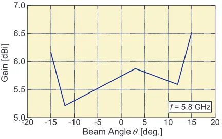
Figure 13 shows the measured antenna gain with respect to the beam angle where the bias voltages of the phase shifter are adjusted. The gain variation over different beam angles is less than ±0.7 dB. The simulated gain of the proposed antenna is 8.9 dBi for the beam direction θ = 0◦, whereas the measured gains in different bias voltages are in 5.2 to 6.5 dBi range. From previous experiments in our laboratory, 2-dB gain difference between simulated and experimental results was observed for a single patch microstrip antenna. Other reasons for the gain difference between simulated and measured results are the difference of the insertion loss of the two phase shifters and magic-T. Furthermore, the diodes are replaced by open circuits, and the capacitors are not considered in the simulation.
7.0
6.5
6.0
5.5
5.0
Gain [dBi]
-20 -15 -10 -5 0 5 10 15 20
Beam Angle θ [deg.]
f = 5.8 GHz
Figure 13. Measured gain with respect to the beam angle. The gain variation is less than ±0.7 dB.
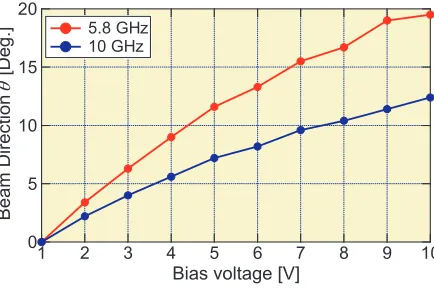
Figure 14 shows a comparison of the beam shift characteristics of the 5.8- and 10-GHz antennas. The result is obtained by calculating beam direction from Eq. (1), where phase shift value is obtained from the simulation result of the phase shifters for two different frequencies. These results are consistent with measured ones. The beam shifting operation of the 5.8-GHz antenna is larger than the 10-GHz beam tracking antenna as the same varactor diodes are used in the phase shifters for both the frequencies.
5. H-PLANE BEAM TRACKING ANTENNA DESIGN
5.1. Structure
20
15
10
5
0
Beam Direction
θ
[Deg.]
10 9 8 7 6 5 4 3 2 1
Bias voltage [V] 5.8 GHz
10 GHz
Figure 14. Comparison of the beam shift characteristics of 5.8- and 10-GHz antennas.
Figure 15 shows the structure of the proposed beam tracking antenna for H-plane. As the two antenna elements are fed from the same side of the patches, Σ signal can be obtained from the microstrip line and Δ signals from the slot line. Therefore, Σ and Δ signals are obtained from Port 1 and Port 2, respectively. Thus, changing the phase shift value, anH-plane beam tracking operation can be achieved.
Magic-T
Phase Shifter
Slot Line
Microstrip
Antenna x
x y
z
θ
y z
Port 1 Σ
Δ Δ
Port 2
A A'
A A'
Σ
Figure 15. Structure of the proposedH-plane beam tracking antenna.
5.2. Simulation Result
Figure 16 shows the simulated reflection coefficient of Port 1 and Port 2. The reflection coefficient is less than−10 dB at the designed frequency of 5.8 GHz.
-30 -25 -20 -15 -10 -5 0
Reflection Coeffici
ent [dB
]
6.4 6.2 6.0 5.8 5.6 5.4 5.2 5.0
Frequency [GHz]
S11 S22
Figure 16. Simulated return loss of the Port 1 and Port 2 of the proposed antenna.
-20 -15 -10 -5 0 5 10
Ga
in [dBi]
-90 -60 -30 0 30 60 90
Angleθ [Deg.]
f= 5.8 GHz
Σ Δ
Figure 17. H-plane radiation pattern of the proposed antenna.
6. CONCLUSION
A new beam tracking concept is proposed, and a 5.8-GHz prototype beam tracking antenna is designed, fabricated and measured. The proposed concept is successfully confirmed by the theoretical, simulated and measured results of the proposed antenna. By using a magic-T, the beam tracking function can be achieved in a simple configuration suitable for a planar antenna. A different configuration antenna is also proposed in this paper to accomplish the beam tracking inH-plane. This concept can give a scope of future work for the beam tracking principle. The proposed antenna can be used for a wide variety of applications in wireless communications and radar technology.
ACKNOWLEDGMENT
The authors would like to thank Dr. Takayuki Tanaka, Saga University for his fruitful discussions and Tatsumi Nomura, a former student of Saga University for the basic evaluation of the proposed antenna. This work was supported in part by JSPS KAKENHI Grant Number 26420361.
REFERENCES
1. Haupt, R. L. and M. Lanagan, “Reconfigurable antennas,” IEEE Antennas and Propag. Mag., Vol. 55, No. 1, 49–61, 2013.
2. Pierro, V., V. Galdi, G. Castaldi, I. M. Pinto, and L. B. Felsen, “Radiation properties of planar antenna arrays based on certain categories of aperiodic tilings,”IEEE Trans. Antennas and Propag., Vol. 53, No. 2, 635–644, 2005.
3. Ibrahim, S. M., “Some properties of planar array antennas formed by symmetry rotation of linear array antenna,” 1989 IEEE Antenna and Propag. Society Int’l Symp. Dig. (AP-S 1989), Vol. 2, 706–708, 1989.
4. Brown, E. R., C. D. Parker, and E. Yablonovitch, “Radiation properties of a planar antenna on photonic-crystal substrate,”J. Opt. Soc. Am. B, Vol. 10, No. 2, 404–407, 1993.
5. Toyoda, I. and E. Nishiyama, “Advanced planar antennas integrated with microwave circuits for RF signal processing applications,” Proc. 10th Asia-Pacific Eng. Res. Forum on Microwaves and
Electromagnetic Theory (APMET2014), 111–115, 2014.
6. Aikawa, M. and H. Ogawa, “Double-sided MICs and their applications,” IEEE Trans. Microwave Theory &Tech., Vol. 37, No. 2. 406–413, 1989.
8. Tanaka, R., E. Nishiyama, and I. Toyoda, “A mono-pulse DOA estimation antenna integrated with RF amplifiers and detection circuits,” 2014 IEEE Int’l Symp. Antennas and Propag. and
USNC-URSI Radio Sci. Mtg. (2014 AP-S/USNC-URSI) Dig., 526.3, 2014.
9. Kederer, W. and J. Detlefsen, “Directon of arrival (DOA) determination based on monopulse concepts,”Proc. 2000 Asia-Pacific Microwave Conf. (APMC2000), 120–123, 2000.
10. Kondo, T., Y. Ushijima, E. Nishiyama, M. Aikawa, and I. Toyoda, “Beam steering microstrip array antenna with orthogonal excitation,”Proc. 2012 Asia-Pacific Microwave Conf. (APMC2012), Vol. 2A5-04, 67–69, 2012.
11. Sato, K., K. Nishikawa, and T. Hirako, “Development and field experiments of phased array antenna for land vehicle satellite communications,” 1992 Antennas and Propag. Society Int’l Symp. (AP-S 1992) Dig., 1073–1076, 1992.
12. Son, S. H., S. Y. Eom, and S. I. Jeon, “A novel tracking control realization of phased array antenna for mobile satellite communication,” Proc. Vehicular Tech. Conf. 2003 (VTC 2003), 2305–2308, 2003
13. Rashid, R., E. Nishiyama, and I. Toyoda, “Prototype evaluation of a beam tracking antenna using magic-T,”Proc. 2015 Int’l Symp. on Antennas and Propag. (ISAP2015), 940–943, 2015.
14. Stutzman, W. L. and G. A. Thiele, Antenna Theory and Design, John Wiley & Sons, New York, 1998.
15. Aikawa, M. and E. Nishiyama, “Compact MIC magic-T and the integration with planar array antenna,” IEICE Trans. Electron., Vol. E95-C, No. 10, 1560–1565, 2012.
16. Aikawa, M. and H. Ogawa, “A new MIC magic-T using coupled slotlines,”IEEE Trans. Microwave Theory &Tech., Vol. 28, No. 6, 523–528, 1980.
![Figure 7 shows the structure of the phase shifter which consists of a de Ronde’s coupler [17] and varactordiodes](https://thumb-us.123doks.com/thumbv2/123dok_us/1922886.1252415/6.612.189.432.260.422/figure-shows-structure-shifter-consists-ronde-coupler-varactordiodes.webp)