Scholarship@Western
Scholarship@Western
Electronic Thesis and Dissertation Repository
8-17-2011 12:00 AM
Workflow-Net Based Cooperative Multi-Agent Systems
Workflow-Net Based Cooperative Multi-Agent Systems
Yehia T. Kotb
The University of Western Ontario
Supervisor
Dr. Steven beauchemin
The University of Western Ontario Joint Supervisor Dr. John Barron
The University of Western Ontario Graduate Program in Computer Science
A thesis submitted in partial fulfillment of the requirements for the degree in Doctor of Philosophy
© Yehia T. Kotb 2011
Follow this and additional works at: https://ir.lib.uwo.ca/etd
Part of the Artificial Intelligence and Robotics Commons, Other Computer Sciences Commons, and the Theory and Algorithms Commons
Recommended Citation Recommended Citation
Kotb, Yehia T., "Workflow-Net Based Cooperative Multi-Agent Systems" (2011). Electronic Thesis and Dissertation Repository. 228.
https://ir.lib.uwo.ca/etd/228
This Dissertation/Thesis is brought to you for free and open access by Scholarship@Western. It has been accepted for inclusion in Electronic Thesis and Dissertation Repository by an authorized administrator of
WORKFLOW-NET BASED COOPERATIVE MULTI-AGENT SYSTEMS
(Spine title: Cooperative Multi-agent Systems)
(Thesis format: Monograph)
by
Yehia Kotb
Graduate Program in Computer Science
A Thesis submitted in partial fulfillment
of the requirements for the degree of
Doctor of Philosophy
The School of Graduate and Postdoctoral Studies
The University of Western Ontario
London, Ontario, Canada
c
CERTIFICATE OF EXAMINATION
Supervisor:
. . . . Dr. Steven Beauchemin
Co-Supervisor:
. . . . Dr. John Barron
Examiners:
. . . . Dr. Xiaobu Yuan
. . . . Dr. Ken McIsaac
. . . . Dr. Marc Moreno Maza
. . . . Dr. Mike Bauer
The Thesis by
Yehia Thabet Kotb
entitled:
Workflow-net based Cooperative Multi-agent Systems
is accepted in partial fulfillment of the requirements for the degree of
Doctor of Philosophy
. . . . Date
. . . .
Chair of the Thesis Examination Board
Abstract
Workflow-nets are mathematical frameworks that are used to formally describe, model and
im-plement workflows. First, we propose critical section workflow nets (abbreviated WFCSnet).
This framework allows feedbacks in workflow systems while ensuring the soundness of the
workflow. Feedback is generally not recommended in workflow systems as they threaten the
soundness of the system. The proposed WFCSnet allows safe feedback and limits the
maxi-mum number of activities per workflow as required. A Theorem for soundness of WFCSnet
is presented. Serializability, Separability, Quasi-liveness and CS-Properties of WFCSnet are
examined and some Theorems and Lemmas are proposed to mathematically formalize them. In
this Thesis, we define some formal constructs that we then build upon. We define the smallest
formal sub-workflow that we call a unit. We propose some mathematical characteristics for the
unit and show how it can be used. We study similarities between units and whether two units
can be used interchangeably or not. We then use composites out of simple units to build more
complex constructs and we study their properties. We define the concept of cooperation and
propose a mathematical definition of the concept. We discuss the concept of task coverage and
how it affects cooperation. We claim that task coverage is necessary for any task to be achieved
and therefore, a necessity for cooperation. We use mathematical methods to determine the task
coverage and the candidate cooperative partners based on their capabilities that can contribute
to the desired task. Workflow-net based cooperative behaviour among agents is proposed.
First, we propose a cooperative algebra, which takes the desired objective of cooperation as a
plan and then transforms this plan into a workflow-net structure describing dependencies and
concurrency among sub-workflow elements constituting the overall plan. Our proposed
among agents. We then propose a cooperative framework with operators that assign tasks to
agents based on their capabilities to achieve the required task.
Keywords: Workflow-net, Multi-Agent cooperation
Acknowledgement
I would like to thank my supervisors, Dr. Steven Beauchemin and Dr. John Barron, for their
enormous help which lead to a successful completion of my Thesis. Drs. Beauchemin and
Barron gave me countless hours to go over problems, were always extra helpful with whatever
questions I had, and even provided me with extra financial aid to help my family and I survive.
I would like to thank my wife for her support and love. I would also like to thank my
brother, parents, other members of my family and my friends who have helped me. Thanks
also to other professors who have guided me during my graduate studies at Western.
Certificate of Examination ii
Abstract iii
List of Figures ix
1 Introduction 1
1.1 Thesis Contributions . . . 1
1.2 Thesis Contents . . . 2
2 Literature Survey 4 3 Introduction To Petri-nets 12 3.1 Characteristics of Petri-nets . . . 18
3.1.1 Reachability . . . 18
3.1.2 Livness . . . 19
3.1.3 Boundness . . . 20
3.1.4 State Machine . . . 21
3.1.5 Marking Graph . . . 21
3.2 Siphons . . . 22
3.3 Petri-net Symbols . . . 22
3.4 Workflow-nets . . . 24
4 Critical Section Workflow-nets 30 4.1 Critical Sections and Workflow-nets . . . 31
4.2 Quasi-Liveness and CS-property . . . 38
4.3 Separability and Serializability . . . 39
4.4 Conclusion . . . 41
5 Cooperation Algebra 42 5.1 Cooperation Algebra . . . 42
5.1.1 Predicates . . . 43
5.1.2 The∧Operator . . . 43
5.1.3 The∨Operator . . . 46
5.1.4 The→Operator . . . 49
5.1.5 ThedenOperator . . . 50
5.2 A Cooperative Algebra Example . . . 52
6 Workflow-net Based Cooperation 55 6.1 Contribution . . . 55
6.2 Preliminaries . . . 56
6.3 Choice Dependency and Unit Similarity . . . 58
6.4 Redirecting Activities to Similar Units . . . 62
6.4.1 Examples of Cooperation . . . 63
6.4.3 Demonstration . . . 67
6.5 The Cooperative Operator . . . 68
6.6 Description of Algorithm . . . 69
6.6.1 Definitions . . . 69
6.6.2 Complete Algorithm . . . 70
6.7 Framework Scalability . . . 73
6.8 Proof of Scalability . . . 74
6.9 Experimental Simulations . . . 75
6.9.1 Experimental Set-Up . . . 75
6.10 Limitations . . . 76
7 Conclusion 81
Bibliography 84
Curriculum Vitae 93
List of Figures
3.1 The structure of a Petri-net. . . 13
3.2 The firing of a Petri-net. . . 14
3.3 Choice dependent Petri-nets . . . 15
3.4 The Petri-net for the dining philosophers problem. . . 16
3.5 Petri-net synchronization. . . 17
3.6 A non-reachable output in a Petri-net. . . 19
3.7 Reachable markings in a Petri-net. . . 20
3.8 A strongly connected Petri-net. . . 21
3.9 State Machine and Marking Graph Petri-nets examples. . . 22
3.10 A Petri Net that is both a state transition and a marking graph. . . 22
3.11 An example of a Siphon. When place P5 loses its marking, it will never again be sufficiently marked. . . 23
3.12 The three dimensions of a Workflow-net. . . 25
3.13 Controlled Siphon. . . 27
3.14 Non-Separable workflow-net. . . 28
3.15 Non-Serializable workflow-net. . . 29
4.1 A critical section workflow-net. . . 32
4.3 Bandwidth of critical sections. . . 41
5.1 The AND operator . . . 44
5.2 The OR operator . . . 47
5.3 The Then operator . . . 50
5.4 Applying Critical sections on predicates . . . 51
6.1 Choice dependency . . . 59
6.2 Concept of similarity . . . 61
6.3 Compositions . . . 62
6.4 Two cooperating Petri-nets . . . 63
6.5 Workflow model for robot activities . . . 64
6.6 A cooperative solution for two robots . . . 65
6.7 Experiment 1. . . 77
6.8 Experiment 1. . . 79
6.9 Experiement 2. . . 80
Chapter 1
Introduction
Cooperative multi-agent systems is a crucial research topic in the field of robotics. Cooperative
behavior is sometimes necessary for a multi-robot task, such as robot soccer. At other times it
is beneficial for increasing performance. In this Thesis, we use an extension of Petri-nets called
workflow-nets to solve the problem of cooperative multi-agent systems. Multi-robot systems
are the case study for the proposed framework. We use workflow-nets to model the behavior
of every agent involved in a cooperation process. Barron [13] used Petri-nets to model the
synchronization communication of actions in an editor-referee system. The work presented in
this Thesis is more encompassing than that as well as being provably theoretically sound.
1.1
Thesis Contributions
The following are the contributions of the Thesis:
1. We introduce a framework that synchronizes activities in mutually exclusive
workflow-nets (critical sections),
2. We introduce a cooperative composite logic-based algebra for recursive workflow-net
construction and
3. We introduce a workflow-net based cooperative framework for autonomous multi-agent
cooperation.
1.2
Thesis Contents
This Thesis is organized as follows:
Chapter 2 surveys the current research on cooperative agents and workflow-nets.
Chapter 3 gives an introduction to Petri-nets and workflow-nets. In this Chapter, all the
re-quired concepts are presented and illustrated. These concepts are the bases for many proposed
Theorems and Lemmas throughout this Thesis.
Chapter 4 introduces a new model for workflow-nets. This model deals with feedback
and synchronization between cascaded activities in an automated operation. The proposed
model is called workflow-nets with critical sections WFCSnet. It guarantees the soundness
of a workflow-net while using feedback. A Theorem and Lemma of soundness are presented.
Another Theorem shows the relationship between the soundness of a WFCSnet and the
quasi-liveness and the CS-properties of that same net.
Separability and serializability are two features that are desirable in workflow-nets. Chapter
4 presents the two concepts and gives a Theorem that shows the soundness of a WFCSnet with
serializability and separability.
Chapter 5 demonstrates a new composite logic based algebra for constructing a closed form
1.2. ThesisContents 3
Chapter 6 proposes a cooperative framework using workflow-nets. The Chapter starts with
a definition of a minimum cooperative object (we call this a unit). It also provides a
mathemat-ical description for what we call choice-independent units, similar units and identmathemat-ical units. We
expand the definition to include sub-workflow-nets which are composed of several units (we
call them compositions). We propose a Theorem of soundness for our cooperative framework.
We then propose a cooperative operator. We then expand our platform to include N agents
and we study its behavior when performing deterministic and non-deterministic time-sensitive
Literature Survey
Robot-based problems such as robotic navigation often benefit from the advantages provided
by multiple, cooperating mobile agents [16, 31, 41]. Such gains include improved performance
and simplicity of robot design. In addition, there are common multi-agent tasks that cannot
be carried out by a single robot, such as playing soccer and follow-the-leader swarms [8].
Conversely, predator-prey and terrain exploration problems are examples of tasks that can be
performed by a single agent yet may be more efficiently addressed with multiple robots [9].
Cooperation among a group of robots is defined as the process of allocating and managing
available resources to achieve a certain goal. Typically, these resources include time, actions,
knowledge, sensor readings and computations. As such, a cooperative situation must satisfy
various constraints on the goal, the tasks, and the robots themselves. These constraints can be
summarized as:
1. Constraints on the nature and the amount of resources to be assigned to each robot and
the time frame in which the goal must be reached,
5
2. Constraints on the tasks to perform, such as precedence ordering and the amount of time
to complete tasks and
3. Constraints on task and robot synchronization.
Cooperating mobile agents must negotiate for resources and perform task planning and
schedul-ing in order to accomplish common goals.
Aalstet-al. introduced the modeling of workflow systems with an extension to Petri-nets,
known as workflow-nets [56, 54]. A workflow-net is a Petri-net with unique input and output
places, and is said to be sound if it is possible for a token in the input place to reach the output
place. Aalst also introduced constructs for token routing known as AND split and join, and OR
split and join [1, 55].
Petri-net composition is an active area of research [62, 27, 65, 63, 48], where services may
be composed on the basis of complementarity. For instance, send and receive services are
complementary by nature and may be composed [10]. Most of the Petri-net based services
are composed directly. Direct composition is the process of fusing two or more Petri-nets
in a single one which provides a complete service. Strict conditions apply in direct Petri-net
composition: for two communicating services A and B, the structure of messages received by
A must match that of messages sent by B, andvice-versa. Services A and B must also consent
to an exchange sequence for the composition to be logically correct [62]. In practice, direct
composition is difficult because service designers cannot always anticipate the need for future
composition.
Wei et-al. propose a web service composition methodology based on mediators which
me-diator is an object that is built upon the services that need to be composed and works as an
interface which unify their input and output message structures. The main objective of service
composition using mediators is to fuse incompatible services.
Baldanet-al. and Aalstet-al. both introduce an extension to Petri-nets calledopen
Petri-nets [10, 11, 57]. An open Petri-net is a workflow-net in which special sets of places act as
service access points. The principle of soundness may not be respected in workflow-nets which
possess multiple service access points. To overcome this problem, both Baldan et-al. and
Aalstet-al. classified these access points into two types: the workflow places and the external
places, acting as interfaces for the intermediate activity states [10, 57]. Two open Petri-nets
can be composed by external places if and only if these types of places are complementary.
This direction of research focuses on coupling services into a producer-consumer relationship.
Work distribution models have been investigated with the use of colored Petri-nets [49].
In a similar way, Aldredet-al. examine communication abstractions for distributed business
processes [7]. These recent advances address process integration and distribution with various
forms of Petri-net compositions.
Pederson proposed a technique to determine the minimum flow of composed Petri-nets
given the minimal flows of its components [47]. The notion of minimum flow is addressed
in the context of transition-based and place-based compositions. Determining the minimum
flow is interesting in many applications as it represents the minimum processing required for
an outcome.
Kindler et al. introduce a weaker condition for global soundness, first proposed by Aalst
[33, 55]. According to Aalst, every sub-workflow must terminate with a token in its output
7
in determining the global soundness of the composed workflow.
Recently, Lima et al. [39] introduced various types of Petri-nets to model distinct views
of the robotic task model, in addition to quantifying task performance and using learning
tech-niques to improve the general efficiency of execution. However, soundness properties1 were
not addressed and it remains unclear whether his framework can guarantee successful
cooper-ative goal completion. Zhang proposed a Petri-net framework for task-level planning [67] in
which an algorithm that depends only on the goal and the constraints required to derive action
sequences is proposed. Gerkey and Matari [26] presented a domain-independent framework
for multi-robot task allocation in which it is shown that task-allocation may be thought of as
an instance of the optimal assignment problem. Alternatively, Noborio and Edashige [45]
pro-posed an on-line, deadlock-free path-planning algorithm for multiple agents operating in an
infinite world. Sauro et al. [53] proposed a framework that defines the cooperation problem
using three modules: the environment module, the action module, and the agent module. Both
the environment and the actions are modeled with a labeled-transition system where the states
represent the environment and the edges represent the various actions taken by the agent within
the environment. Each pair of states is connected with a single edge to represent the possibility
of the environment changing its state from state S to stateS0, when an action is performed.
The agent is defined by the set of actions it can perform. In this case, the cooperation of two
or more agents is the union of the two or more action sets that belong to the agents. The main
disadvantage of this approach is that it cannot represent concurrency in a direct way.
More-over, when the environment is complex and the number of agents exceeds a certain limit, the
framework becomes unsuitable for many applications, especially those that need to maintain
real-time performance measures.
Herzig and Longin [32] developed a new logic of intention which addresses the problem of
cooperation. They showed that cooperation not only involves the contribution of some agent
to goal satisfaction but also the adoption of the beliefs and intentions of that agent so as to
indirectly allow it to achieve its goal. They proposed various techniques for belief adoption
and intention generation. However, they did not propose a solution for the case where two or
more beliefs contradict each other.
Chaimowicz et al. [18] proposed a technique for tightly coupled multi-robot cooperation,
in which robots work in concert to achieve a common goal. Their work focused on merging
communication with simple control techniques in order to achieve cooperation. Their platform
allows heterogeneous robots with different sensors and control mechanisms to cooperate in
order to achieve complex goals. Their platform was tested using a follow-the-leader task.
Chonget al. [22] proposed a coordination control between telerobots in such a way as to
overcome the problem of delayed round-trip signals. Their testing environment consisted of
two robots and two human operators who remotely controlled the robots. Thus, the robots were
not fully autonomous and their coordination approach was aimed at solving the delay problem
only.
Botelho and Alami [15] proposed a decentralized multi-robot system scheme for loosely
coupled task planning and negotiation. The main protocol consists of three services: task
allocation, cooperative reaction and task execution. Task allocation is achieved by sending the
same set of tasks to be executed to all robots, followed by a negotiation for task selection. Each
robot creates a plan for achieving the task under consideration. Those robots unable to generate
9
are considered candidates. The best candidate is chosen by the robot asking for the service. A
cooperative reaction occurs when a robot fails to achieve its task. The robot asks for help and
evaluates the offers from other robots to choose the best one. If no other robot responds, the
failed robot abandons the task. The execution task is responsible for synchronization between
the set of cooperative robots and the execution of the required tasks. Together, these three
services constitute a framework the authors call M+.
Alamiet al. [4, 6] proposed a framework for multi-robot systems called the Martha Project.
The Martha project deals with trans-shipment tasks using multi-robot systems (from 10 to 100
robots). The system is comprised of a central station and a set of autonomously guided vehicles
that communicate among themselves and with the central station. They proposed a topological
graph-based environment model that is suitable for the problem of robot cooperation. The
topological graph models areas, routes, and docking stations. The model is known to each
autonomous vehicle and when a task is submitted to a robot from the central station, it is
required to refine the plan generated to achieve the task after coordinating the route access
with the other robots. The coordination is achieved through a plan-merging paradigm that
guarantees a conflict-free overall plan for the cooperating robots.
Linet al.[40] proposed an agent-based robot control that achieves multi-robot cooperation
for environment exploration. The proposed approach depends on merging the partial
environ-ment maps simultaneously obtained by many robots to constitute a complete mapping. Their
experiments show good results when using two robots. However, the problem of coordinating
more than two robots was not specifically addressed.
An interesting approach to robot cooperation was proposed by Yingyinget al. [66]. They
param-eters that can be tuned to create different modes of personalities for the robots. The authors
claim that giving the agents their own personality produces more cooperation modes. These
modes can lead to better performance for the multi-agent system. They did not show how these
modes can be controlled to yield a better performance.
Al-Jumaily and Kozak [3] proposed a robot cooperation framework that is based on
nego-tiation. The negotiation among agents is achieved in several steps. The first step, performed by
the agent who is required to attend to a task, is to negotiate with other agents, by broadcasting
the negotiation request to all. In the meantime, all other agents listen to the broadcast. These
steps (Broadcasting and Listening) achieve together the data sharing that is required for the
agents to negotiate. The third step is for every agent to calculate its distance to the negotiator.
After calculating all distances, a decision is made. The robot that is closest to the target is the
one that will achieve the required goal.
Brokowski et al. [14] proposed a robot cooperation framework based on Finite State
Au-tomata (FSA). They designed cooperation protocols using FSA between two robots to
manip-ulate and displace objects within a simple environment. The model they used did not address
the problem of scalability. It is known that the complexity of representing concurrency with
FSAs increases exponentially with the number of agents. To avoid this problem, they claimed
that their framework is only applicable in simple environments.
Chan and Yow introduced a strategy-driven framework for multi-robot cooperation [20].
They used robot soccer as an application to demonstrate their framework. Each team has a
set of strategies stored in a database in the form of a multi-dimensional cube. Each node of
this cube is a single strategy and, according to the context, a team may change its strategy
11
for the whole team. However, cooperation between robots is not explicitly achieved; their
work represents a role assignment based on a predefined set of global plans rather than explicit
Introduction To Petri-nets
Petri-nets were invented by Carl Adam Petri in 1939 for the purpose of describing chemical
processes. He documented the Petri-net in 1962 as part of his dissertation,Kommunikation mit
Automaten (communication with automata). Petri’s work significantly advanced the fields of
parallel and distributed computing and it helped define the modern studies of complex systems
and workflow management.
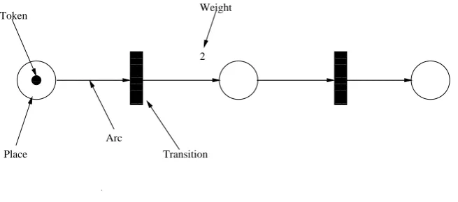
A Petri-net is a directed bipartite graph with two types of nodes, namely places(circles)
and transitions(solid rectangles). Transitions model discrete events that may occur. Places
are pre- or post-conditions for the transitions they are connected to. Places and transitions are
connected via directed weighted arcs and if these arcs are not weighted than the weight is
assumed to be one. These integer weights determine the number of activities that flow from
places along the arcs per transition. These activities are calledtokens(small solid circles that
reside by places). The distribution of tokens over places is called amarking. Figure 3.1 shows
the structure of a Petri-net.
Arcs connect places to transitions and transitions to places but they never connect two
13 00 00 00 11 11 11 00 00 00 00 00 00 00 00 00 00 11 11 11 11 11 11 11 11 11 11 0 0 0 0 0 0 0 0 0 0 1 1 1 1 1 1 1 1 1 1 0000000
1111111 000000111111000000111111
000 000 000 000 000 000 000 000 111 111 111 111 111 111 111 111 000 000 000 000 000 000 000 000 000 111 111 111 111 111 111 111 111 111 000 000 000 000 000 000 000 000 111 111 111 111 111 111 111 111 0000 0000 0000 0000 0000 0000 0000 0000 1111 1111 1111 1111 1111 1111 1111 1111 00 00 00 00 00 00 00 11 11 11 11 11 11 11 000000 111111 Place Token Arc Transition Weight 2
Figure 3.1: The structure of a Petri-net.
nodes of the same type together. When arcs run from places to a transition, these places are
input places to this transition, and, when they run from a transition to places, these places
are output places to this transition. A transition in a Petri-net is enabledif and only if there
are tokens in all the input places to this transition and each input place contains a number of
tokens that is greater than or equal to the weight of its connecting arc to this transition. After
a transition is enabled, it will eventually fireby consuming tokens from its input places and
producing tokens in its output places. The number of produced/consumed tokens per place is
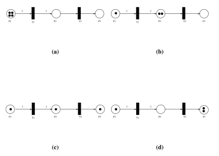
equal to the weight of the arc that connects this place with this transition. Figure 3.2 shows
the firing process of a Petri-net. Figure 3.2(a)shows a petri-net with an initial marking of 4
tokens in placeP1. TransitionT1is enabled because placeP1has more tokens than the weight
of the arc toT1. In figure 3.2(b), transitionT1 fires and 3 tokens are consumed fromP1 and
2 tokens are produced in place P2 because the weight of the arc that goes fromT1 toP2 is 2.
TransitionT2is then enabled. Consequently, in figure 3.2(c), transitionT2fires and a token is
still enabled and another token is consumed fromP2and a new token is produced inP3. Notice
that transitionT1 is never enabled again during the scenario because the number of tokens in
placeP1is less than the weight of the arc that joinsP1andT1.
00 00 00 11 11 11 00 00 11 110 0 0 1 1 1 0 0 1 1 0 0 0 0 0 0 0 0 0 0 1 1 1 1 1 1 1 1 1 1 00 00 00 00 00 00 00 00 00 00 11 11 11 11 11 11 11 11 11 11 000000
11111100000001111111 00000001111111 0000011111
3
P1 T1 P2 T2 P3 2 0 0 0 1 1 1 00 00 00 11 11 11 00 00 00 11 11 11 0 0 0 0 0 0 0 0 0 0 1 1 1 1 1 1 1 1 1 1 00 00 00 00 00 00 00 00 00 00 11 11 11 11 11 11 11 11 11 11 000000
11111100000001111111 00000001111111 0000011111
3
P1 T1 P2 T2 P3 2 (a) (b) 0 0 0 1 1 1 0 0 0 1 1 1 0 0 0 1 1 1 0 0 0 0 0 0 0 0 0 0 1 1 1 1 1 1 1 1 1 1 00 00 00 00 00 00 00 00 00 00 11 11 11 11 11 11 11 11 11 11 0000000
111111100000001111111 00000001111111 0000011111
3
P1 T1 P2 T2 P3 2 0 0 0 1 1 1 0 0 1 1 0 0 0 1 1 1 0 0 0 0 0 0 0 0 0 0 1 1 1 1 1 1 1 1 1 1 00 00 00 00 00 00 00 00 00 00 11 11 11 11 11 11 11 11 11 11 000000
11111100000001111111 00000001111111 0000011111
3
P1 T1 P2 T2 P3 2
(c) (d)
Figure 3.2: The firing of a Petri-net:(a)A petri-net with an initial marking of 4 tokens in place
P1. (b) TransitionT1fires and 3 tokens are consumed from P1 and 2 tokens are produced in
placeP2. (c)Transition T2 fires and a token is consumed from P2 and a token is produced in
P3. (d)TransitionT2 is still enabled and another token is consumed fromP2and a new token
is produced inP3.
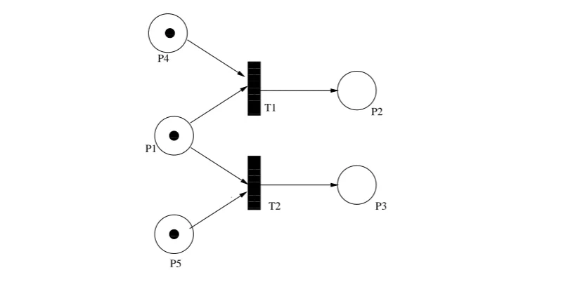
Two transitions that have the same input place are called choice-dependent and in this
15
fired while the other has to wait to be re-enabled again. Figure 3.3 shows a Petri-net of two
transitions that are not choice-free (choice-dependent).
0 0 0 1 1 1 00 00 00 11 11 11 0 0 0 1 1 1 0 0 0 0 0 0 0 0 0 1 1 1 1 1 1 1 1 1 0 0 0 0 0 0 0 0 0 1 1 1 1 1 1 1 1 1 0000000 1111111 0000000 1111111 P3 P2 T2 T1 P1 P4 P5
Figure 3.3: Transitions T1 and T2 are choice-dependent because if one of them fires, it will
disable the other from firing. This is a non-deterministic case of Petri-nets, any one of them
could fire before the other.
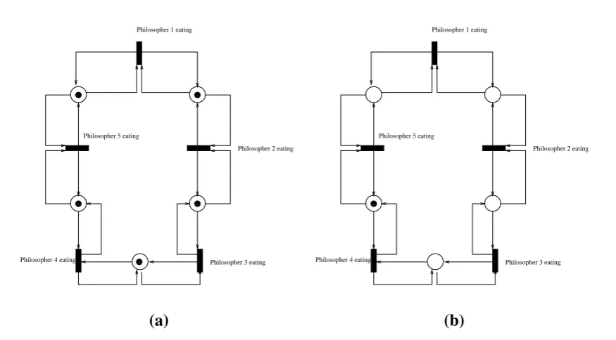
Consider a Petri-net for the famous dining philosopher’s problem as shown in Figure 3.4.
This problem illustrates a common multi-process synchronization problem first presented by
Dijkstra and Hoare [61, 24]. The dining philosophers problem is summarized as five
philoso-phers sitting at a circular table to either eat spaghetti or think. Eating and thinking actions in
this problem are mutually exclusive and therefore any philosopher can either eat or think at
any point of time. Between each pair of adjacent philosophers there is a fork that is placed
and therefore, each philosopher has a fork on his left hand side and another one on his right
to eat and a philosopher can only use the forks on his immediate left and right. In Figure 3.4,
0 0 0 1 1 1 0 0 0 1 1 1
0 0 0 1 1 1 0 0 0 1 1 1
00 00 00 11 11 11
Philosopher 1 eating
Philosopher 2 eating
Philosopher 3 eating Philosopher 4 eating
Philosopher 5 eating
0 0 0 1 1 1
Philosopher 1 eating
Philosopher 2 eating
Philosopher 3 eating Philosopher 4 eating
Philosopher 5 eating
(a) (b)
Figure 3.4: The Petri-net that models the dinning philosophers problem. Tokens in this case
represent forks. (a)The initial state of the five philosopher model with forks on the right and
left-hand sides of each philosopher.(b)The Petri-net marking when philosophers one and three
eating. After they finish eating the transitions consume the tokens and the marking becomes
like that shown in(a).
forks are represented by tokens. Transitions represent the action of eating. When a transition is
enabled and consequently fires (consumes two token from the two input place, one from each
place) then the philosopher that is represented by this transition is eating. If the transition is
enabled but did not fire yet or is not enabled at all then the philosopher represented by this
transition is thinking.
17 00 00 00 11 11 11 00 00 00 11 11 11 00 00 00 11 11 11 00 00 00 11 11 11 0 0 0 0 0 0 1 1 1 1 1 1 0000 0000 1111 1111 0000 0000 1111 11110 0 0 0 0 0 1 1 1 1 1 1 0 0 0 0 0 0 1 1 1 1 1 1 0 0 0 0 0 0 1 1 1 1 1 1 0 0 0 0 0 0 1 1 1 1 1 1 0 0 0 0 0 0 0 1 1 1 1 1 1 1 0000 0000 1111
1111 0000000011111111
0 0 0 0 0 0 1 1 1 1 1 1 0 0 0 0 0 0 1 1 1 1 1 1 000 111 0000 1111 00000 00000 00000 11111 11111 1111100
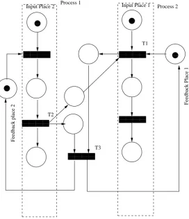
0 0 0 0 1 1 1 1 1 1 0000 1111 Process 1 Process 2 T1 T2 T3
Input Place 1 Input Place 2
Feedback place 2
Feedback Place 1
Figure 3.5: Two processes are modeled by a Petri-net. The two processes can not accept
any new input unless both transitionsT1 andT2 have been executed. Such synchronization is
achieved by using transitionT3, which only becomes enabled when both T1 and T2 are fired.
WhenT3is fired, it enables one or both transitions (T1andT2) depending on which input places
have tokens. Note that Process 2 can not deliver an output token unless Process 1 is executed.
The 2 processes are delimited by the dashed lines.
modeling. This Petri-net can model two processes working together. The second feature is
process reaches a certain point in its execution, as defined by the model. The third feature is
execution dependency. Note that Process 2 can not be executed until Process 1 is finished. Also
note that the marking in the feedback places must be as shown for the very first execution.
3.1
Characteristics of Petri-nets
Characteristics of Petri-nets can be classified intostructuralandbehavioralproperties.
Struc-tural properties are those that describe how the Petri-net is built and how the topology describes
the execution of tasks within the system. An example of these characteristics is boundness.
Some higher level structural description for Petri-nets are state machine, marking graph, and
siphons. Behavioral properties are those properties that describe how the machine will
be-have during run time. The behavioral properties depend on the structural properties and initial
marking of the Petri-net. Examples for these properties are reachability, soundness, livness,
serializability, separability and Controlled Siphons. In this Section, we describe some of the
structural and bevabioral properties of the Petri-nets that is discussed through out this thesis.
3.1.1
Reachability
Thereachability of a Petri-net depends on whether a certain marking can be obtained in the
Petri-net from an initial marking. To study such a feature of Petri-nets, a reachability graph is
constructed to determine all possible marking in this net, given some initial marking. Examples
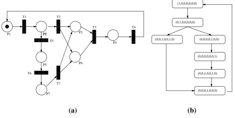
of reachability are shown in Figures 3.6 and 3.7. As shown in the Figure 3.6,T3 needs tokens
in bothP3andP6to be enabled and consequently fired. T2andT5are competing for the token
3.1. Characteristics ofPetri-nets 19 0 0 0 1 1 1 00 00 00 00 00 00 00 11 11 11 11 11 11 11 0 0 0 0 0 0 0 1 1 1 1 1 1 1 00 00 00 00 00 00 00 11 11 11 11 11 11 11 000 000 000 111 111 111 000 000 000 111 111 111 0 0 0 0 0 0 0 1 1 1 1 1 1 1 0 0 0 0 0 0 0 1 1 1 1 1 1 1 000
111000111 001100001111
000 000 000 111 111 111 000 000 000 000 000 000 000 111 111 111 111 111 111 111 0000
1111 000111 0 0 0 1 1 1 0 0 0 0 0 1 1 1 1 1 0 0 0 0 0 1 1 1 1 1 0 0 0 0 0 1 1 1 1 1 0000 0000 0000 0000 0000 0000 1111 1111 1111 1111 1111 11110000 0000 0000 0000 0000 0000 1111 1111 1111 1111 1111 1111 P2 P3 P5 P7 P6 P4 P1 P1 T1 T2 T3 T4 T5 T6 T7 (1,0,0,0,0,0,0) (0,1,0,0,0,0,0) (0,0,1,0,0,0,0) (0,0,0,0,1,0,0) (0,0,0,0,0,0,1) (0,0,0,0,0,1,0) (a) (b)
Figure 3.6: Non-reachable markings in a Petri-net.(a): A Petri-net with an output place that is
not reachable and(b): A reachability graph for the Petri Net shown in(a).
reside in eitherP3 orP6, depending on whetherT2 orT5 will fire, and therefore,T3will never
be enabled with this marking, and therefore,P4 will never be marked. Figure 3.7, on the other
hand, shows a case of reachability. The output of this Petri-net is reachable provided that
transitionT5consumes the token in placeP2 before transitionT2does. The Petri-net in Figure
3.8 isstrongly connectedin that every node in the Petri-net is reachable from any other node
in this Petri-net and therefore this net represents full reachability.
3.1.2
Livness
Thelivnessof a Petri-netℵis a property that indicates whether all the transitions that belong to
ℵcan be enabled or not. A Petri-net with fully reachable transitions is an example of liveness.
0 0 0 1 1 1 00 00 00 00 00 00 00 11 11 11 11 11 11 11 0 0 0 0 0 0 0 1 1 1 1 1 1 1 00 00 00 00 00 00 00 11 11 11 11 11 11 11 000 000 000 111 111 111 000 000 000 111 111 111 0 0 0 0 0 0 0 1 1 1 1 1 1 1 0 0 0 0 0 0 0 1 1 1 1 1 1 1 000
111000111 001100001111
000 000 000 111 111 111 000 000 000 000 000 000 000 111 111 111 111 111 111 111 0000
1111 000111 0 0 0 1 1 1 0 0 0 0 0 1 1 1 1 1 0 0 0 0 0 1 1 1 1 1 0 0 0 0 0 1 1 1 1 1 0000 0000 0000 0000 0000 0000 1111 1111 1111 1111 1111 11110000 0000 0000 0000 0000 0000 1111 1111 1111 1111 1111 1111 P2 P3 P5 P7 P6 P4 P1 P1 T1 T2 T3 T4 T5 T6 T7 (1,0,0,0,0,0,0) (0,1,0,0,0,0,0) (0,0,1,0,0,0,0) (0,0,0,0,1,0,0) (0,0,0,0,0,0,1) (0,0,1,0,0,1,0) (0,0,0,1,0,0,0) (a) (b)
Figure 3.7: Reachable markings in a Petri Net. (a): A Petri Net with an output place that is
reachable and(b): A reachability graph for the Petri Net shown in(a).
enabled or fired. Figure 3.8, on the other hand, shows a live Petri-net because all transitions
can be enabled.
3.1.3
Boundness
Boundnessis a structural property of a Petri-net. It indicates how many tokens can reside in
each place at any time. The maximum capacity for all places is the boundness of a Petri-net. If
a Petri-net is 1-bound (the capacity for every place is a single token) then the Petri-net is said
3.1. Characteristics ofPetri-nets 21 0 0 0 0 0 1 1 1 1 1 0 0 0 0 0 0 1 1 1 1 1 1 0000 0000 0000 0000 0000 1111 1111 1111 1111 1111 000 000 000 000 000 000 000 111 111 111 111 111 111 111 0 0 0 0 0 0 1 1 1 1 1 1 P2 P3 P5 P7 P6 P4 P1 P1 T1 T2 T3 T4 T5 T6 T7 0 0 0 1 1 1 0 0 1 1 00 00 00 00 00 00 11 11 11 11 11 11 0 0 0 0 0 0 1 1 1 1 1 1 0 0 0 0 0 0 0 1 1 1 1 1 1 1 0000 0000 0000 1111 1111 1111 0000 0000 1111 1111 0 0 0 0 0 0 0 1 1 1 1 1 1 1 0 0 0 0 0 0 0 1 1 1 1 1 1 1 000
111000111 0011 000111
000 000 000 000 111 111 111 111 000 000 000 000 000 000 000 111 111 111 111 111 111 111 000
111 00001111
(0,0,1,0,0,1,0) (0,0,0,0,0,0,1) (0,0,0,0,1,0,0) (0,0,1,0,0,1,0) (0,1,0,0,0,0,0) (1,0,0,0,0,0,0) (0,0,0,1,0,0,0) (a) (b)
Figure 3.8: A strongly connected Petri-net. (a): Every node in this Petri-net is reachable from
any other node that belongs to this net. (b): A reachability graph for the Petri Net shown in
(a). The graph shows that any marking can be reached from any other marking.
3.1.4
State Machine
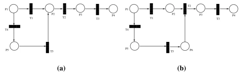
A Petri-net is said to be astate machineif and only if for every transition there is a single input
place and a single output place. Figure 3.9(a)shows a Petri-net that is a state machine while
Figure 3.9(b)shows a Petri-net that is not a state machine (transitionT2 has 2 input places).
3.1.5
Marking Graph
A Petri-net is said to be amarking graphif and only if for every place there is a single input
transition if any, and a single output transition if any. Figure 3.9(b)is a marking graph. Figure
00 00 00 00 00 00 11 11 11 11 11 11 00 00 00 00 00 00 11 11 11 11 11 11 0 0 0 0 0 0 1 1 1 1 1 1 0000
1111 00001111 00011100001111 000111 000111
000 000 000 111 111 111 0 0 0 0 0 0 1 1 1 1 1 1 0 0 0 0 0 0 0 0 1 1 1 1 1 1 1 1 0 0 0 0 0 0 0 0 0 1 1 1 1 1 1 1 1 1 000000000 1111111110 0 0 0 0 0 0 0 0 0 0 0 0 0 0 0 0 0 1 1 1 1 1 1 1 1 1 1 1 1 1 1 1 1 1 1 P3 P4 T1 T2 T3 P1 P2 T5 P5 T4 00 00 00 00 00 00 11 11 11 11 11 11 00 00 00 00 00 00 11 11 11 11 11 11 0 0 0 0 0 0 1 1 1 1 1 1 0000
1111 00001111 00011100001111 000111 000111
000 000 000 111 111 111 0 0 0 0 0 0 1 1 1 1 1 1 0 0 0 0 0 0 0 0 1 1 1 1 1 1 1 1 0 0 0 0 0 0 0 0 0 1 1 1 1 1 1 1 1 1 000000000 11111111100001111
P3 P4 T1 T3 P1 P2 T5 T4 T2 P5 P6 (a) (b)
Figure 3.9: Different Petri-net structure nets. (a): A State Machine Petri-net and(b): A
Mark-ing Graph Petri-net.
00 00 00 00 00 00 11 11 11 11 11 11 00 00 00 00 00 00 11 11 11 11 11 11 0 0 0 0 0 0 1 1 1 1 1 1 0000
1111 00001111 00011100001111 00001111 000111
P2 P3 P4
T1 T2 T3
P1
Figure 3.10: A Petri Net that is both a state transition and a marking graph.
3.2
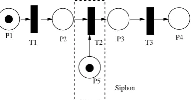
Siphons
A Siphon is a place that is if insufficiently marked; it will never receive new tokens. An
example of a siphon is placeP5 as shown in Figure 3.11.
3.3
Petri-net Symbols
The following Petri-net symbols occur most often in the literature and are used through out this
3.3. Petri-netSymbols 23
P1
T1 P2 T2 P3 T3 P4
P5
Siphon
Figure 3.11: An example of a Siphon. When placeP5loses its marking, it will never again be
sufficiently marked.
- •tis the set of input places to transitiont
- t•is the set of output places from transitiont
- •pis the set of transitions that are connected to place pas input
- p•the set of transitions that are connected to place pas output
- |Niis the reachable set of nodes from nodeN
- | •t|is the number of input places to transitiont
- |t• |is the number of output places to transitiont
- Pis the set of places
- T is the set of transitions
- pk is the place numberk
- iis the set of input places of a Petri-net
- ois the set of output places of a Petri-net
- M(k) orMk is the Petri-net marking in step numberk
- M(0) is the initial marking of the Petri-net
- Mois the output marking of the Petri-net
- A∈ |BimeansAis reachable from B.
Mathematically, a Petri-net is a 4-tuple:
ℵ =< P,T,F,W >, (3.1)
wherePis a set of places,T a set of transitions, Fa set of arcs between transitions and places,
expressed asP×T ∪T ×P, andW is a vector containing the weights of the arcs inF.
3.4
Workflow-nets
Workflow management and business engineering processes consider industrial systems
com-posed of business processes competing for resources [35]. The workflow space is spanned by
three dimensions [35]. The 1st dimension is the control flow dimension, which is concerned
with the partial ordering of tasks. The 2nd dimension is the resource dimension, in which
resources are classified by identifying roles and organization units. The 3rd dimension of a
workflow is concerned with individual cases. Figure 3.12 shows the different dimensions of
3.4. Workflow-nets 25
Control
Case
Workflow Activity Resources
Figure 3.12: The three dimensions of a Workflow-net.
Workflow-nets (WFnet) are used to model the structural and dynamic behaviors of
work-flows. The structural behavior of a workflow defines task dependencies and their structure
which guarantees the desired output. The dynamic behavior is how the structure reacts online
with activities which are handled by the workflow. A workflow-net is a special type of
Petri-net that has two special places,iando, wherei is the only place that does not have any input
transitions andois the only place that does not have any output transitions. Nodesiandoare
called the source andsink nodes. Workflow-nets are preferred over normal Petri-nets in
in-dustrial applications because they guarantee the success of the inin-dustrial process (soundness).
The following are definitions for Workflow-nets and their characteristics.
Definition 1 A Petri-netℵis a WFnet if and only if
2. ℵhas an output place o, where o•=φand
3. if a transition t∗ is added toℵ such that •t∗ = o and t∗• = i, the Petri-net ℵ∗ becomes
strongly connected.
Note that t∗is a transition which connects the input to the output of the WFnet.
In the above definition, •i is the set of all input transitions to placei ando• is the set of
output transitions from place o. When a Petri-net is strongly connected, there is a sound path
between any two transitions in the net.
One of the Petri-net properties that is considered essential to workflow-nets is the property
of soundness. Soundnessguarantees that the Petri-net will eventually terminate and, at this
moment, there will be tokens in the output place and all other places will be empty. This
signifies that all activities will reach the output place and none of them will be ”lost” inside the
net. When automating a process, it is essential to make sure that the Workflow-net is sound.
Definition 2 A WFnetℵis sound if:
1. ∀M ∈ |Mii, Mo∈ |Mi,
2. ∀Mk ∈ |Mii,i f Mk ∈ |Moi then Mk = Moand
3. ∀t ∈T, ∃M ∈ |Mii, t∈ |Miand Mo ∈ |ti
whereM is a marking of the WFnet,Mi is the input marking,Mo is the output marking,Mk is
the marking at timekandtis a transition.
Other important properties of Petri-nets are SafenessandQuasi-Liveness. A Petri-net is
3.4. Workflow-nets 27
means that∀ti ∈T,tiis firable in a finite time given marking M. In other words, all transitions
will eventually be enabled and fired. If a transitionT can not be enabled, then this transition is
said to bestarving. To guarantee the success and the feasibility of applying workflow-nets in
industry the following three definitions are needed.
Definition 3 The Controlled Siphons property (CS-property) states that a siphon is controlled,
if and only if, for each reachable marking, the siphon remains sufficiently marked. A Siphon is
a place that is, if insufficiently marked, will never again get new tokens.
Figure 3.13 shows placeP5as controlled siphon. This place is guaranteed to remain sufficiently
marked through the firing ofT3.
P1
T1 P2 T2 P3 P4
P5
T3
Controlled siphon
Figure 3.13: Controlled Siphon.
Definition 4 Separability is a behavioral property which states that the behavior of a
workflow-net with k tokens in the initial node is seen as a combination of the behavior of k copies of the
net, each of them with one token in the initial node.
Figure 3.14 shows a workflow-net that is not separable. Th two transitionsT1 andT2 have
T1
T2 P1
P2
P3
T3 P4
P5
P6
T4
T5
Enabling T5 depends on the firing of T3 and T4
Figure 3.14: Non-Separable workflow-net.
So the two activities represented by the two tokens depend on each other for them to reach the
output.
Definition 5 Serialisability requires that the set of traces of a workflow-net with id-marking
(in this case each token has an identifier) is equal to the set of traces of an abstraction of the
workflow-net. In other words, an activity that exists in a workflow does not effect any other
activity that co-exists in that same workflow.
In other words, Serializability is the ability of seeing the execution of cascaded activities in a
workflow-net as if each of them owns the workflow-net execlusively at any time.
Figure 3.15 shows a workflow-net that is not serializable. it is also not separable. A token
needs to be consumed byT3in order to enableT2. This means that the marking of one activity
depends on the marking of the other.
Serialisability and Separability are related. Serialisability views the workflow as a pipeline
3.4. Workflow-nets 29
T1
T2 P1
P2
P3
P4
P5
P6
T4
T5 T3
P7
Critical Section Workflow-nets
The concept of workflow management systems first appeared in the field of business process
management [1]. Since then, workflow management has been applied to a wide spectrum of
applications. Kotbet al. proposed a workflow management based health care operating system
[35, 38, 37]. In later research, Kotbet al. proposed a workflow based cooperative platform for
multi-robot systems [36]. Since there is a large diversity of scientific applications, each field
presents its own view of workflow.
A Scientific Workflow Management System (SWMS) is a group of software modules that
handles the modeling and the execution of a scientific experiment. It also models the
dependen-cies among experiment activities and processes and manages resource allocation and utilization
during the experiment [69]. In the last decade, this type of research has been done in the grid
computing field and has made complex and intensive experimental processing feasible [68, 69].
4.1. CriticalSections andWorkflow-nets 31
4.1
Critical Sections and Workflow-nets
One of many things that makes applying workflow-nets on scientific applications infeasible is
Workflow-net constraints. One of these constraints is that feedback and loops1 are not
per-mitted, as it threatens the soundness of the system [1]. Some workflow systems have critical
sections, a set of tasks that can only be executed by one activity at a time. This type of
work-flow needs very careful handling so that the critical sections are maintained. Real time
require-ments are fulfilled if and only if the soundness property is guaranteed. We control a critical
section in a workflow-net using a special feedback net. This net controls the flow of activity
in the workflow-net while maintaining system soundness. We call this net a critical section
workflow-net (denoted CSnet). This net is itself a workflow with special tokens known as
con-trol tokens. The original workflow-net and one or more of the concon-trol nets constitute what we
call a workflow-net with critical sections (denoted WFCSnet). An example of a WFCSnet is
shown in Figure 4.1. The following are definitions for our proposed WFCSnet:
Definition 1 A critical section is a workflow-net or a sub-workflow-net that can not serve more
than n activities at a time, where n is an integer,1 ≤ n ≤ k, and k is the maximum number of
activities that can flow in the critical section at any point of time.
Definition 2 A CSnetΨis a control net for WFnetℵif:
1. Ψis a sound WFnet,
2. iΨis the input place of Ψsuch that∃ ti ∈ ℵwhere iΨ∈ti•,
3. oΨis the output place of Ψsuch that∃ to ∈ ℵwhere oΨ ∈ •to and
0 0 0 1 1 1 0 0 1 1 0 0 0 0 0 0 0 1 1 1 1 1 1 1 0 0 0 0 0 0 0 1 1 1 1 1 1 1 0 0 0 0 0 0 0 1 1 1 1 1 1 1 0 0 0 0 0 0 0 1 1 1 1 1 1 1 0 0 0 0 0 0 0 1 1 1 1 1 1 1 P5 Pc1 Pc2 Tc T4 P4 T3 P1 T2 P2 T1 P1 Workflow net Control net
Figure 4.1: A critical section workflow-net denoted as WFCSnet. The WFnet is defined by
{P1,T1,P2,T2,P3,T3,P4,T4,P5}. The input place isP1and the output place isP5. The control
net CSnet is defined by{Pc1,Tc,PC2}. Note thatM(Pc2) is part of the initial marking, otherwise
the net is not sound. After an activity is executed,PC2must have the same inital marking. This
is the minimum sufficient marking forPC2as a controlled siphon. The initial marking of PC2
determines the number of activities that can flow in the controlled workflow-net at any point of
time.
4. Ψ∩WFnet= {iΨ×ti∪to×oΨ}where ti ∈WFnet and to ∈WFnet and ti ∈ | toi.
Definition 3 A WFCSnet can be described in terms of a WFnet and a CSnet as follows:
WFCSnet=WFnet [
CSnet. (4.1)
Definition 4 A WFCSnetℵis a 5-tuple:
4.1. CriticalSections andWorkflow-nets 33
where P is a set of resource token places in the WFnet, Pc is a set of control places in the
CSnet,T is a set of transitions in the WFnet, andTc is a set of transitions in the CSnet,
F = Fr∪Fc∪Fcr,
Fr =T ×P∪P×T,
Fc =Tc×Pc∪Pc×Tc,
Fcr =T ×Pc∪P×Tc∪Pc×T ∪Tc×P,
W is the set of weights of the arcs of the WFnet,Wc is the set of weights of arcs of the CSnet,
M(0) is the initial marking of WFnet, andMc(0) is the initial marking of CSnet. The weights
ofFcr andFc are bound to 1. Figure 4.1 shows a simple WFnet.
0 0 1 1 0 0 0 1 1 1 0 0 0 0 0 0 1 1 1 1 1 1 0 0 0 0 0 0 0 1 1 1 1 1 1 1 0 0 0 0 0 0 0 1 1 1 1 1 1 1 0 0 0 0 0 0 0 1 1 1 1 1 1 1 0 0 0 0 0 0 0 1 1 1 1 1 1 1 000 000 000 111 111 111 0 0 0 0 0 0 0 1 1 1 1 1 1 1 000 000 000 111 111 111 Pc1 Tc Pc2 Control net P5 T4 P4 T3 T2 P2 T1 P1 Workflow net T5 T6 P3 0 0 1 1 0 0 0 1 1 1 0 0 0 0 0 0 1 1 1 1 1 1 0 0 0 0 0 0 0 1 1 1 1 1 1 1 0 0 0 0 0 0 0 1 1 1 1 1 1 1 0 0 0 0 0 0 0 1 1 1 1 1 1 1 0 0 0 0 0 0 0 1 1 1 1 1 1 1 000 000 111 111 00 00 00 00 00 00 00 11 11 11 11 11 11 11 000 000 000 111 111 111 Pc1 Tc Pc2 Control net P5 T4 P4 T3 P1 T2 P2 T1 P1 Workflow net (a) (b)
Figure 4.2: WFCSnet: Workflow-nets using control nets. a): A WFCSnet that is not sound,
as it violates the 4th condition in Theorem 4.1.1 and hence, the control token is consumed by
T4from placeP3resulting in an insufficient marking in the siphonPc2. b): A WFCSnet that is
Definition 5 The following conditions must exist for a WFnet ℵ = ℵf ∪Ψto be a WFCSnet,
whereℵf is the original WFnet andΨis the CSnet:
1. ℵf =hP,T,Fr,Wiis a sound WFnet,
2. Ψ =hPc,Tc,Fc,Wciis a sound CSnet,
3. P, ∅and Pc ,∅and P∩Pc =∅,
4. T ,∅and Tc ,∅and T ∩Tc =∅,
5. ∀Mk ∈[M(0)iand Mck∈[M(0)i, if Mk = M(0)then Mck= Mc(0)and
6. ∀f ∈Fcr, f is sound.
As stated earlier, it is essential to guarantee soundness in workflow systems. In Figure 4.2,
there are two models of WFCSnet. The model on the left-hand side is a WFCSnet that is not
sound, whereas the one on the right-hand side is sound. The following Theorem defines the
soundness of the WFCSnet.
In the following Theorem, we are adopting the following symbols:
- ℵis the controled WFnet
- Ψis the control net CSnet that is applied onℵ
- ℵf is WFCSnet whereℵf =ℵ ∪Ψ
- Pciis the input place ofΨ
4.1. CriticalSections andWorkflow-nets 35
- iis the input place forℵ
- ois the output place forℵ
- tiis a single transition that hasPcoamong its input places
- tois a single transition that hasPciamong its output places
- is a non-empty set of tokens
- M(W F) is the marking of Workflow-netW F
- T is the set of transitions inℵ
- Pis the set of places inℵ
- TC is the set of transitions inΨ
- PC is the set of places inΨ
Theorem 4.1.1 A WFCSnetℵf is sound if and only if:
1. ∀ Mk such that Mk ∈ | M(0)∪Mc(0) i, Mo ∈ | Mk i,
2. Ψ is a sound WFnet with Mc(0)= Mc(Pco) andMc(0)> 0,
3. ℵ ∩Ψ ={Pco×ti∪to×Pci}and
4. ∀ tk ∈ | ti i, to ∈ |tk i or ∃ tj | tj =• •tk and to < | •tk i.
Proof 1. Since Ψ is a sound WFnet with Mc(0) = Mc(Pco) and Mc(0) > 0, and
2. therefore∃ ∈ •ti.
3. Since∀ tk ∈ | ti i, to ∈ |tk i or ∃ tj | tj =• •tk and to < | •tk i,
4. therefore will not deviate to a non-sound path and will always be in a state that yields
Mo.
5. Since∀ Mk such that Mk ∈ | M(0)∪Mc(0) i, Mo ∈ | Mk i,
6. therefore∀ ∈ M(0), will eventually be inMo,
7. therefore if the conditions of Theorem 4.1.1 are satisfied, thenℵf is a sound WFnet.
We now show the converse, namely that if the WFCSnet is sound, then these conditions are
satisfied:
Proof 1. Sinceℵf is sound,
2. therefore tokens will always reach placeo.
3. Since all tokens will eventually be part ofMo,
4. therefore∀ Mk such thatMk ∈ | M(0)∪Mc(0) i, Mo∈ | Mk i, and ∃ ti|Pco =•ti
and
5. Pco is sufficiently marked.
6. SincePcois sufficiently marked,
7. thereforeΨis a sound WFnet and ∃to ∈ ℵ|to =•Pci.
4.1. CriticalSections andWorkflow-nets 37
9. Sincetois always reachable fromti,
10. therefore tokens do not move through a route that does not lead toti.
11. therefore∀ tk ∈ | ti i, to ∈ |tk i or ∃ tj | tj =• •tk and to < | •tk i.
Hence,ℵf is sound when thesenecessaryconditions are satisfied.
Figure 4.2 shows a case when condition 4 of the Theorem is violated. Note that the number
of activities allowed in the critical section is equal toM(Pco), which determines thebandwidth
of the critical section. To extend the Theorem to allowNtokens to coexist in the critical section,
Ψis anN-bound WFnet. To allow a single activity at a time,Ψmust be safe.
Lemma 4.1.2 If a WFCSnet ℵf is sound then its WFnet ℵ is sound and its control net Ψ is
also sound.
We do not need to demonstrate this Lemma as the proof is implicit in the Theorem.
Lemma 4.1.3 For a sound WFCSnetℵf, if the marking ofℵisM(0) then the marking ofΨis
Mc(0).
Proof 1. Sinceℵf is sound:
2. thereforeti will eventually be fired and will consume a token fromPco, and,
3. to ∈ |ti i2.
4. Sincetowill eventually fire,
5. therefore a tokenwill be produced inPci.
6. Sinceℵis sound, thereforeo ∈ |toi.
7. Hence the marking ofℵwill eventually be iniandoonly,
8. SinceΨis sound,
9. therefore the marking ofΨwill be inPcoonly.
10. therefore ifM(ℵ)= M(0) then M(Ψ)= Mc(0).
4.2
Quasi-Liveness and CS-property
The following Theorem binds between the soundness, Quasi-liveness and the CS-property of a
WFCSnet:
Theorem 4.2.1 A WFCSnet is sound if and only if it is Quasi-Live and it satisfies the
CS-property.
We start with proving that if a WFCSnet, ℵ is sound, then it is Quasli-liveand satisfies the
CS-property.
Proof 1. Sinceℵf is sound,
2. therefore∀Mk ∈ | Mi, Mo ∈ |Mki,
3. therefore∀tk T, tk is firable in a finit time,
4. thereforeℵf is quasi-live.
4.3. Separability andSerializability 39
6. therefore∀ •tk ∈P,•tk is sufficiently marked,
7. therefore the CS-property is maintained.
Now we show the converse, namely, if the critical section workflow-net is quasi-live and
maintains the CS-property then it is sound.
Proof 1. Since CS-property is satisfied,
2. therefore∀ •t ∈ T, •tis always sufficiently marked.
3. Sinceℵf is quasi-live,
4. therefore∀t∈ T, T is firable given marking M,
5. therefore•ois firable,
6. therefore∀, will evenyually be ino,
7. thereforeℵf is sound.
4.3
Separability and Serializability
Separability and serializability are two dynamic behavior properties in workflow-nets as stated
in definitions 3.4. Feedback affects such properties and therefore we investigate these features
in this Section.
We define the N-Separability for a WFCSnet as follows:
Definition 7 Thedegree of Separabilityis the maximum number of activities that can be
Definition 8 N-Separability is a behavioral property which states that the behavior of a
workflow-net withktokens in the initial node can be seen as a combination of the behavior ofN copies
of the net, each of them with an average of Nk tokens in the initial node, whereN is the number
of control tokens inPco.
Note that N-Separability is fully maintained ifK ≤ N, whereKis the number of activities
in the system andNis the number of control tokens inPco.
Theorem 4.3.1 For a WFCSnet, ℵf, if ℵf is sound, then it also satisfies the properties of
Serialisability and N-Separability.
Proof 1. Sinceℵf is sound,
2. therefore∃Mk such thatMk ∈ | M(0)∪Mc(0)iandMo ∈ | Mk i,
3. therefore∃σsuch thatσis a firing sequence, whereM(0)−→σ Mo.
4. Since ℵf is Quasi-live3, then ∃ {t1,t2, ...,tn} ∈ T, such that t1
σ1
−−→ t2
σ2
−−→ t3...
σn−1
−−−→ tn,
wherenis a finite integer number andσn−1 yields the system for markingMo,
5. thereforeσ1 →σ2 →... →σn−1 ≡σ,
6. thereforeℵis serializable.
7. Since it is serializable and from Lemma 4.1.3, It is anN-Separable.
Lemma 4.3.2 A WFCSnet ℵf with m critical sectionsΨi is k-separable, where k is the
mini-mum initial marking of Ψi andΨi ∈ Ψand1 ≤ i≤m.
4.4. Conclusion 41 0 0 1 1 00 00 11 11 00 00 00 11 11 11 0 0 1 1 0 0 0 0 0 0 1 1 1 1 1 1 0 0 0 0 0 0 1 1 1 1 1 1 0 0 0 0 0 0 1 1 1 1 1 1 0 0 0 0 0 0 1 1 1 1 1 1 00 00 00 00 00 00 11 11 11 11 11 11 0 0 0 0 0 0 1 1 1 1 1 1 P5 T4 P4 T3 P1 T2 P2 T1 P1 Workflow net
1 token bandwidth 2 tokens bandwidth
A B
Figure 4.3: Bandwith of critical sections. Critical section A has a bandwidth of two tokens.
Critical section B has a bandwidth of 1 token. The overall bandwidth of the workflow-net is
then 1-token.
Lemma 4.3.2 shows that the bandwisth of the whole controlled workflow-net is equal to the
minimum bandwidth of its critical sections as shown in figure 4.3.
4.4
Conclusion
In this Chapter a solution for introducing feedback and controlled loops into workflow-nets is
presented. A Theorem of soundness for the proposed WFCSnet is given. We also proposed
a Theorem for Quasi-Liveness and CS-property satisfaction. Serializability and separability
Cooperation Algebra
This Chapter describes our cooperative algebra for solving workflow problems. We propose
operators that join a number of workflow-nets into a larger one. The algebra describes exactly
how we build incident matrices that describe the Workflow-net compositions.
5.1
Cooperation Algebra
In this Section we show how a logical description of a plan is converted into our chosen
rep-resentation of workflow-nets using the cooperative operator⊗, as applied to create the incident
matrices corresponding to logical operators. These are the and (∧), the or (∨), the then (→)
’ and the critical section (den) operators1. In this Chapter, we also study commutativity,
as-sociativity, and distributivity properties of the operators in two aspects, logical and structural.
An operator can be logically associative but structurally non-associative. This applies to other
1Thenotoperator or any higher level operator based on it (such asxor) are not used within this framework due
to their lack of meaning in the workflow.
5.1. CooperationAlgebra 43
properties as will be seen later in this Chapter. An operator has a structural property if and
only if applying this property on the operands does not affect the incident matrix built with the
operator.
5.1.1
Predicates
In this framework, every predicate is transformed into a unit with a single input and a single
output place. For instance, given predicateA, its incidence matrix is formed as
IA =
1
−1
. (5.1)
Initially, all predicates within the logical description of a cooperative plan are given incident
matrices. Given an incident matrixI, we adopt the following definitions:
p(I) ≡ number of rows inI, equivalent to the number of places,
t(I) ≡ number of columns inI, equivalent to the number of transitions,
po(I) ≡ row number of the output place inI and
pi(I) ≡ row number of the input place inI,
which are used in the construction of incident matrices, resulting from applying the cooperation
operator⊗.
5.1.2
The
∧
Operator
Theandoperator∧joins the incident matrices of its predicates, yielding a new incident matrix
equivalent to the following:
IA∧IB =
1 −1 ∧ 1 −1
= IA∧B, (5.2)
where IA∧B is the incident matrix. It is the ∧ operator that gives rise to parallelism in the
resulting workflow-net. For example, A∧ B signifies that A and B can be accomplished in
parallel, given that enough resources with the required task coverage are available.
00 00 00 00 00 00 00 11 11 11 11 11 11 11 0 0 0 0 0 0 0 1 1 1 1 1 1
1 0000
00 00 00 00 00 11 11 11 11 11 11 11 0 0 0 0 0 0 1 1 1 1 1 1 0 0 0 0 0 0 0 1 1 1 1 1 1 1 00 00 00 00 00 00 00 11 11 11 11 11 11 11 B A A and B
A B
Figure 5.1: The application of AND operator to two workflow-nets.