Design study and Modeling of Surface
Plasmon Resonance (SPR)-based Optical
Fiber Sensor Utilizing Zinc Oxide and Gold
Layers
Murtadha F.S. Al-saaidy1, Shehab A. Kadhim2, Ali A.D. Al-Zuky3, Anwar H.M. Al-saleh4
Department of physics, Collage of Science, Al-Mustanasiya University, Iraq 1,3,4
Laser & Optoelectronics Research Center, Ministry of Science & Technology, Iraq2
ABSTRACT:A surface plasmon resonance (SPR) based fiber optic sensor for physical, chemical and biological
sensing applications using a gold layer coated around a small unclad portion of an optical fiber and the zinc oxide layer
coated over it has been presented and theoretically analyzed using four layer model designed and modeled using Matlab. The complete analysis of the sensitivity of sensing for various values of gold and zinc oxide layer thickness has been done numerically within the range of refractive index between 1.3 and 1.4. In this study the optimized values of gold and zinc oxide layer thicknesses were 40nm and 20nm respectively and the sensitivity was 3.556µm/RIU.
KEYWORDS: surface plasmon resonance, sensor, fiber optic, zinc oxide.
I. INTRODUCTION
the suitable material limited by some limitations like it is chemically vulnerable against oxidation and corrosion, therefore, its protection is required for a stable sensing application. Gold has a good feature in these types of sensors. Zinc oxide has also attracted the significant interest of research, community due to being widely used in numerous applications such as transparent conducting films, photonic crystals, gas sensors, bio sensors, light emitting diodes, solar cells, lasers, photo electrochemical cells and electrodes [9,10,11,12 ]. Besides, zinc oxide does not get easily oxidized when comes in contact with the surrounding ambience.
II. THEORETICAL CONCEPTS
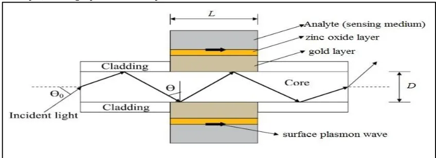
The principle of surface plasmon resonance sensor based on attenuated total reflection (ATR) with Kretschmann’s configuration. This configuration consists of a coupling prism, which can be replaced by the core of optical fiber, a metal layer of thickness (d1) and dielectric function (Ԑm) and an outermost absorbing medium of dielectric function (Ԑs). The cladding around the core from the middle portion of an optical fiber is removed and coated with a thin film of metal like gold, this film is finally surrounding by the sensing medium. The light from polychromatic source is launched into one end of the fiber using proper optics (lens) and the transmitted light is detected and analyzed at the other end of the fiber. The idea, is when the incident light makes total internal reflection at the metal-dielectric interface, the evanescent waves excite the surface plasmons on the metal surface and when the propagation constant of the wave of these plasmas matched to that of the evanescent wave, a strong absorption of light takes place as a result of energy transferring and then the output signal demonstrates a sharp dip at certain wavelength known as resonance wavelength.
III. MODELING AND SIMULATION
As shown in figure (1) the sensing region of SPR-based optical fiber sensor can consist of four layers mainly are Fiber core, Metal layer, Sensing layer and the analyte.
Figure (1): schematic diagram of four layer SPR-based fiber optic sensor.
III.I.I. THE CORE OF OPTICAL FIBER
The core of optical fiber considered to be made of fused silica in which the refractive index variation with wavelength as shown in the dispersion relation [13].
n1 = 1 + + + ………..…… (1)
Where: a1=0.6961663, a2=0.4079426, a3=0.8974794, b1=0.0684043, b2=0.11622414, and b3=9.896161 are slimmer coefficients.
And λ is the wavelength (in µm) of light propagating in the medium.
III.I.II.THE METAL LAYER
silver (Ag) and gold (Au) have ability to be used for an SPR sensor. The copper has some limitations like silver, it is chemically vulnerable against oxidation and corrosion. The gold is the most sensitive, whereas the aluminum is lost. The dielectric constant of any metal can be calculated according to the Drude model as[14]:
Ԑ (λ) =Ԑ + iԐ =Ԑ −
( ) ……… (2)
Where Ԑmr and Ԑmi are the real part and imaginary part of the metal dielectric constant and λp and λc are the plasma
wavelength and collision wavelengths of the metal respectively.
λp =1.6826 x 10⁻⁷ and λc = 8.9342x10⁻⁶ for the gold metal.
Ԑ∞ is the infrared constant and it is equal to one for the Au, Ag, Cu, and Al metal and equal to 3.8 for ITO.
III.I.III. SENSING LAYER
In four layer model, over the metal layer there is the sensing layer. This layer should have a reversible reaction with the analyte.
The dielectric constant of this medium is (Ԑs). If (ns) is the refractive index of the sensing medium, then Ԑs= ns2. The resonance condition for the excitation of surface plasmon wave is given by:
n sinθ= Re{K } ………. (3)
Where Re {Ksp} is a real part of the propagation constant of the surface plasmon wave which can be written as:
K = = ………. (4)
Where c, ω, λ are the speed of light in vacuum, angular frequency and wavelength of incident light respectively.
The left hand side of equation (3) denotes the propagation constant of the light incident at an angle θ and the right hand
side is the real part of the propagation constant of the surface plasmon wave.
III.I.IV. THE ANALYTE
Chemical, biological, or environmental element that needs to be sensed are called the analytes and it is the surrounding material over the sensing layer. The reaction between this material and the material of the sensing layer result in a new material of different refractive index which leads to shifting in resonance wavelength.
III.II. TRANSMITTED POWER
The p-polarized from a collimated source is launched into the fiber at an axial point through a microscope objective (lens). The power, dP, arriving to the fiber end between the angle θₒ and θₒ+dθₒ is given by [15]:
dp∝
( ) ……. (5)
Where θ is the angle of the ray with the normal to the core-cladding interface, and n1 is the refractive index of the core of the fiber.
For p-polarized light, the general expression for the normalized transmitted power in an SPR-based optical fiber sensor is given by:
P =∫
( )
[ / )
/
∫ / [ / ) …. (6)
Where Nref (θ) is the total number of reflections performed by a ray making an angle θ with the normal to the core -metal interface in the sensing region, and given as:
N (θ) = …………. (7) Where L and D: are the length of sensing region and the fiber core diameter respectively.
The critical angle of the fiberθc is given by:
θ = sin ( ) …. …….. (8)
Where ncl and n1 is cladding and core refractive index, respectively.
any layer are: the thickness (dk), dielectric constant (Ԑk), permeability (µk) and refractive index (nk). The tangential fields at the first boundary z=z1=0 are related to those at the final boundary z=zN-1 by the relation:
U
V = M
U
V ………… (9)
Where U1 and V1 are the tangential components of the electric and magnetic fields respectively at the boundary of the first layer. UN-1 and VN-1 are the corresponding fields at the boundary of Nth layer. M is the characteristic matrix given by:
M =∏ M = MM MM ………. (10)
With
M = −iq sincosβ β (−isincos ββ)/q ..…….. (11)
Where q = cosθ =
( )
………… (12)
and
β = n cosθ (z −z ) = (ε −n sin θ ) ………. (13)
The amplitude reflection coefficient of p-polarized incident light is given by:
r =( ) ( )
( ) ( )…………..…. (14)
The reflectance of the p-polarized incident light is given by:
R = r ………. (15)
IV. THE SENSITIVITY
The sensitivity of surface plasmon resonance sensor is given by [18]:
S = ……… (16)
Where λres is the resonance wavelength corresponding to the refractive index of the sensing medium ns.
V. RESULTS AND DISCUSSION
For theoretical calculations, the refractive index of the sensing medium is changed from 1.30 to 1.4 in steps of 0.02 and the values of the parameters have been used are Numerical aperture of the fiber =0.77, fiber core diameter D=600 µm
and length of the exposed sensing region L=10 mm.
To optimize the thickness of the gold and ZnO layer, the transmitted output power of SPR based fiber optic sensor has
Figure (2): surface plasmon resonance curve at different refractive index values (1.3, 1.32, 1.34, 1.36, 1.38, and 1.4 from left to right) for thicknesses 40nm and 20nm for gold and ZnO layer respectively.
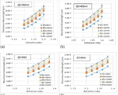
Figure (3) shows the plot of SPR resonance wavelength for 30nm, 40nm, 50nm and 60nm thickness of gold layer and for 0nm, 10nm, 15nm, 20nm, and 25nm thickness of ZnO layer. The resonance wavelength increases linearly with the increase in refractive index of the sensing medium. The slope of each curve in the figure (3) represents the sensitivity of sensing.
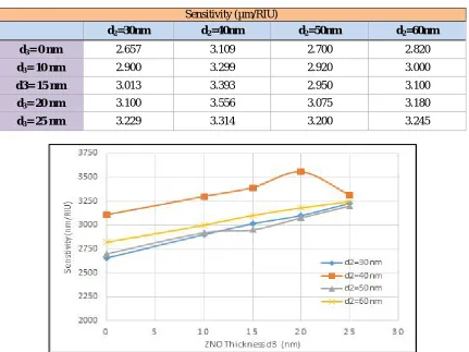
As shown in the table (1) and also in figure (4) the sensitivity increase with the increasing of the thickness of ZnO layer. The largest value of the sensitivity gets in this study were 3.556 µm/RIU at the thicknesses 20nm and 40nm of the ZnO and gold layer respectively.
Table (1): Sensitivity at different thicknesses of gold and ZnO layers.
Sensitivity (µm/RIU)
d2=60nm
d2=50nm
d2=40nm
d2=30nm
2.820 2.700
3.109 2.657
d3= 0 nm
3.000 2.920
3.299 2.900
d3= 10 nm
3.100 2.950
3.393 3.013
d3= 15 nm
3.180 3.075
3.556 3.100
d3= 20 nm
3.245 3.200
3.314 3.229
d3= 25 nm
Figure (4): sensitivity variation with the ZnO thickness (d3) for different values of gold thickness (d2).
VI. CONCLUSION
SPR-based optical fiber sensor utilizing gold and ZnO layers has been theoretically studied. The varying of ZnO and gold layer thicknesses leads to changing of the sensitivity of sensing. The sensitivity, increase as ZnO thickness increase for each thickness of gold layer within the studied ranges. The optimum thicknesses were 40nm for gold and 20nm for ZnO.
REFERENCES
1. Gupta, B.D.; Verma, R.K. Surface plasmon resonance –based fiber optic sensors: Principle, probe, designs and some applications. J. Sens. (2009) dio:10.1155/2009/979761.
2. Alireza, H.; Bertrand, G.; Majid Fassi, F.; Andrei, K.; Maksim, S. Photonic crystal fiber and waveguide-based surface plasmon resonance sensors for application in the visible and near-IR. Electromagnetics" (2008) 25, 198-213.
3. Homola, J.; Yee, S.; Gauglitz, G. Surface plasmon resonance sensors: Review. Sens. Actuators B: Chem. (1999), 54, 3-15. 4. Barnes, W.L.; Dereux, A.; Ebbesen, T.W. Surface plasmon subwavelength optics. Nature (2003), 424, 824-830.
5. Coelho, L.; de Almeida J.M.; Santos, J.L.; Ferreira, R.A.; Andre, P.S.; Viegas,D. Sensing structure based on surface plasmon resonance in chemically etched single mode optical fibers. Plasmonics (2014), doi: 10.1007/s11468-014-9811-3.
7. Jorgenson, R.C.; Yee, S.S. A fiber-optic chemical sensor based on surface plasmon resonance, Sensors and Actuaors B 12 (1993) 213-220. 8. Sharma, A.K.; Jha, R.; Gupta, B.D. Fiber-optic sensors based on surface plasmon resonance: a comprehensive review, Sensors Journal, IEEE7 (2007) 1118-1129.
9. Ma, Y.; Du, G.T.; Yang, S.R.; Li, Z.T.; Zhao, B.J.; Yang, X.T.; Yang, T.P.; Zhang, Y.T.; Liu, D.L., Control of conductivity type in undopedZnO thin films grown by metalorganic vapor phase epitaxy, J. Appl. Phy.95 (2004) 6268-6272.
10. Gupta, S.K.; Joshi, A.; Kaur, M. Development of gas sensors using ZnO nanostructures, J. Chem. Sci. 122 (2010) 57-62.
11. Sharma, R.K.; Patel, S.; Pargaien, K.C. Synthesis, characterization and properties of Mn-doped ZnO nanocrystals, Adv. Nat. Sci. 3 (2012) 035005.
12. Wang, J.X.; Sun, X.W.; Wei, A.; Lei, Y.; Cai, X.P.; Li, C.M.; Dong, Z.L. Zinc oxide nanocomb biosensor for glucose detection, Appl. Phys. Lett.88 (2006) 233106.
13. Kimure, T. Basic concepts of the optical waveguide in optical fiber transmission, K.Noda (Ed), North Holland (1986). 14. Maier, S.A. Plasmonics: Fundamentals and applications, Springer (2007).
15. Gupta, B.D.; Sharma, A.; Singh, C.D. Evanescent wave absorption sensors based on uniform and tapered fibers: a comparative study of their sensitivities. Int. J. Optoelectronic. 8 (1993) 409-418.
16. Hecht, E. Optics, Addison- Wesley Publishing Company (1990).
17. Gupta, B.D.; Sharma, A.K. Sensitivity evaluation of a multi-layered surface plasmon resonance based fiber optic sensor: A theoretical study, Sensors and Actuators B 107 (2005) 40-46.