CDT Analysis as a Diagnostic Parameter for
Evaluating Unbalance Response
Abdul Harees1, Sajeena Harees2
Laboratory Engineer, Department of Mechanical Engineering, The Petroleum Institute, Abu Dhabi, UAE1 Instructor, Department of Physics, College of Arts & Science, Abu Dhabi University, UAE2
ABSTRACT: Coast Down Time Analysis is one of the monitoring technique used in condition-based maintenance of
machinery. Coast down phenomena is the inherent behavior of any rotor systems during the deceleration period. Coast down time (CDT) can be explained as the exact time lapsed between the power cutoff and precise haulting of the system. So the total time taken by the system to dissipate the momentum acquired during sustained operation make the coast down time.
KEYWORDS: Coast down time, Fast Fourier Transform, Vibration monitoring, condition- based maintenance,
deceleration period.
I. INTRODUCTION
The different choices like routine maintenance, condition based maintenance etc was in front of industrial engineers to choose from to make the machinery up and running with maximum productivity. Different techniques are tried around the globe for diagnosing the problems at the initial stages. The most common are vibration analysis and wear monitoring.
The general application of monitoring methods to the detection and definition of machine problems.
Vibration analysis is a powerful tool in the field of condition- based maintenance. It mainly involves the extraction of the diagnostic vibration signal from complex machinery. Vibration analysis can be effectively used to determine the health of the machine and sources, which cause mechanical defects to machine.
Vibration monitoring is a method in which vibration signals from machinery are acquired and using them as information carriers. It is considered as a good indicator of machine health status as most of the machinery problems produce abnormal vibration.
The vibration data is usually collected with a portable device for periodic monitoring, or a continuous monitoring system may be installed for costly or critical systems. Analysis of the vibration data requires a detailed understanding of machinery operations and of vibration analysis techniques.
The instruments used to measure vibration have advanced tremendously in the past three decades. Most important one is the Fast Fourier Transform (FFT) spectrum analyzer, which represents the state of art in vibration measurements. A large portion of the lubricated machinery components will experience wear damage through lubrication failure. Bearings are no exception; lubrication related bearing problems are most frequently caused by lack of lubrication or lubricant contamination.
Tribo monitoring through wear / lubricant analysis can detect lubricant contaminants, machine malfunctions or lubricant deterioration. When the speed of rubbing is considerable and the contamination film is liable to be destroyed, resort is had to lubricants, which possess the power of keeping the surfaces apart, and thereby reducing the friction. Lubricating oil analysis is performed for three reasons: to determine the machine mechanical wear condition, to determine the lubricant condition, and to determine if the lubricant has become contaminated.
total time taken by the system to dissipate the momentum acquired during sustained operation make the coast down time et al [1]. Coast down time in any rotary system depends on following things: Inertia of system components, tribological behaviour of the machine elements like bearings, seals etc
Coast down time reveals the feasible performance of bearings with respect to the lubricating conditions and the lubricants used at given operating conditions if other mechanical conditions are isolated at el [2]. In this project a horizontal rotor system has been fabricated with a shaft supported on both ends on an antifriction bearings. The steady state vibration readings at each rotating speed of the rotor and the lubricants are recorded using an FFT analyzer. The rotor power is cutoff at each speed and deceleration of the rotor is recorded using a non-contact digital tachometer with PC interface. The exact time elapsed between the power cut off and the stoppage of the rotor is therefore obtained. The experiments have been conducted at various cut off speeds and lubricating condition and also for mechanical conditions. The objective is here to evaluate the significance of CDT with respect to various conditions and thereby compare it with steady state vibration
II. CONDITIONBASEDMAINTENANCE
Condition Based Maintenance is a common umbrella referring to Condition Monitoring, Predictive Maintenance, or "Just-In-Time" Maintenance. Condition Based Maintenance is technique related with the identification and measurement of parameters that could be used to identify or predict the chance of failure. This is used to make equipment condition perfect before the failure actually happens. Rotary equipment is important right from concept stage of a project to installation, commissioning and commercial operation. Condition-Based Maintenance enables us to make maintenance decisions based on actual condition, rather than time or usage interval. We can identify equipment problems at an early stage, when they are less costly to correct, and perform maintenance only when needed, and hence increases asset utilization, extends equipment life, and reduce costs of maintenance.
Condition based maintenance is a very effective technique to defend against the risks of unplanned equipment failures. To gain good diagnostic information a combination of measurement parameters appropriate to the machine operating conditions and failure characteristics will be required. Sound engineering judgment and good plant experience is needed for accurate analysis of the data and effective recommendations for corrective actions et al [10].
There is an increasing need for utilities to optimise their expenditure in an increasingly liberalized market. One of the ways to achieve this is through condition-based maintenance instead of the normal time-based maintenance. Condition-based maintenance could help to reduce both maintenance as well as unplanned interruption cost et al [6].
III. VIBRATIONMONITORINGANDANALYSIS
Vibration analysis is the dominant technique used for predictive maintenance management. The vibration from plant machinery can provide direct correlation between the mechanical condition and recorded data of
each machine in the plant. Any degradation of the mechanical condition in the plant machinery can be detected using vibration-monitoring techniques.
Recent advancement in microcomputers technology has simplified the vibration data acquisition, automate data management and minimize the need for vibration experts to interpret data. Commercially available systems are capable of routine monitoring, trending, evaluating and reporting the mechanical conditions of all the equipment. This type of program can be used to schedule maintenance on all rotating and reciprocating process mechanical equipments. Most vibration based predictive maintenance program rely on one or more monitoring techniques such as broadband trending, narrow band trending and signature analysis.
Any malfunction or deterioration of machine health will produce an increased vibration.
Vibration frequencies differ according to the operation.
Individual frequency information is not lost even if mixed vibration data is obtained
Individual component of system has its own frequency and it changes only when the system parameters are affected.
Two strategies for vibration monitoring programme are
1. Condition checking- Condition checking is followed when acceptable vibration levels are fixed.
2. Trend monitoring- Trend monitoring is adopted when it is difficult to get acceptable vibration standards. So in this case vibration is continuously monitored and trend is analyzed.
The technology and techniques have been developing for over 30 years and most of the manufacturing or processing plants use vibration analysis. Vibration analysis of rotating machines such as motors, pumps, fans, and gears is widely accepted as a viable technique to identify changing conditions. Reduced costs of test equipment and data management (primarily computers), availability of training, and development of computer-based expert systems are all contributing to this acceptance. Vibration parameters considered are (i) Amplitude, (ii) Frequency, and (iii) Vibration form.
The technique measures machinery vibration, typically through the use of an accelerometer, and examines the vibration spectrum to identify and trend frequencies of interest. Some frequencies are associated with the machine design, regardless of its condition. For example, a healthy fan or rotary compressor may have a frequency that is equal to the machine speed times the number of fan blades. The vibration analysts may monitor this frequency to note changes in the amplitude indicating a degrading condition. Other frequencies, for example, those associated with rolling element bearings, may be a sign of bearing damage and will alert the analysts to the start of bearing failure. It is common for electric motor problems, such as broken rotor bars or stator eccentricity, to be seen in vibration associated with electrical line frequency. In new equipment, vibration analysis can identify defective bearings and confirm proper alignment and balance at installation et al [5].
Vibration data is usually collected and analyzed on a monthly to quarterly basis on continuously running equipment. Types of vibration monitoring equipment are
1. Portable vibration meters, which are not associated with an external data storage or analysis system. 2. Portable vibration meters, with digital memory and information management systems.
3. Permanently installed monitoring systems with online computer connected.
Vibration in mechanical equipments is not considered as good. It causes excessive wear of bearings, cause cracking, makes fasteners to come loose, solder joints develops crack and results in electronic malfunctions. It also abrades insulation around electrical conductors causing shorts, and finally causes noise et al [8].
The major things behind vibration generation are
Mass imbalance
Misalignment
Resonance
o An audible pure tone
o A clear sine wave in the time domain
o A single tall peak in the frequency domain
Bearings
o Contamination including moisture
o Overstress
o Lack of lubrication
o Defects created after manufacturing.
IV. FASTFOURIERTRANSFORM(FFT)ANALYZERS
A significant role in the way engineers and scientists who measure and analyze signals is being played by Fourier transforms. Even before computers became as accessible as they are today engineers and scientists have used these methods. Computers have significantly improved our ability to analyze and process signals, as Fourier transform calculation requires a tremendous number of multiplication calculations, still it is a daunting and laborious task. During 1960s, a new method known as the fast Fourier transform (FFT) was introduced, and it reduced the number of individual calculations required. The FFT is actually an umbrella term for a class of fast algorithms for computation of the discrete Fourier transform. The mathematical steps employed by fast Fourier transform could be attributed to Gauss in about 1805. The fast Fourier transform is the basis for computer-based spectrum analysis, which relies on the representation of a signal in the frequency domain and is one of the most-commonly used methods to analyze signals and waveforms. It works on the principle that you can express any waveform as a sum of sinusoids. But, it makes one important assumption that the waveform is periodic. i.e. the signal is composed of the same waveforms repeated. When we apply the FFT to the signal of interest, it is broken up into the sum of these sines and cosineset al [11].
V. ROLLINGELEMENTBEARINGFAILURESANDCAUSES
Defective rolling element in a bearing generate vibration frequencies at the rotational speeds of each bearing component and rotational frequencies are related to the motion of the rolling elements, cage and races. The time and frequency domain vibration analysis are widely accepted for detecting incipient malfunction in the bearing.
The first step in designing the bearing mounting is to decide which type and size of bearing shall be used. The choice is generally based on a certain desired life for the bearing. The next step is to design the application with allowance for the prevailing service conditions. Usually too many of the ball and roller bearings installed never attain their calculated life expectancy because of something done or left undone in handling, installation and maintenance.
The calculated life expectancy of any bearing is based on the assumptions that good lubrication in the proper quantity will always be available to that bearing, that the bearing will be mounted without damage,
that dimensions of parts related to the bearing will be correct, and that there are no defects inherent in the bearing et al [9].
The commonly found bearing failures are attributed to the following causes: -
Defective bearing seats on shafts and housing
Misalignment
Faulty mounting practice
Incorrect shaft and housing fit
Inadequate lubrication
Ineffective sealing
Vibration while the bearing is not rotating
Passage of electric current through bearing
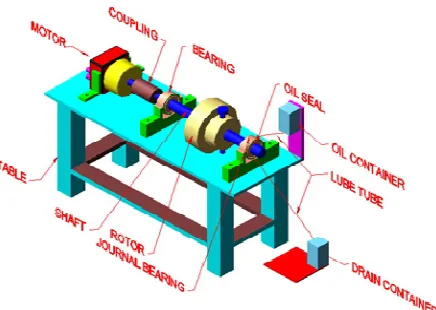
Figure 1 et al [12]
The inherent behavior of any rotating system after the supply is cut off is called as the coast down phenomena. The CDT is the total time taken by the system to dissipate the momentum acquired during sustained operation.
CDT in any rotating system is dependent on 1.Inertia of the system components
2.The tribological behavior of the machine elements. 3.Operating conditions, and
4.Environmental effects such as fluid drag.
During the coast down period the entire system is completely free from the power source, which is an external disturbing parameter. Fluctuation in power source voltage, frequency etc can have appreciable effect et al [4].
The bearing operation and maintenance play a prominent role in machinery reliability, efficiency and safety. Hence the technique to evaluate the performance of a bearing is significant and is also worthwhile to assess the exact tribological process and their mechanical degradation. The tribological process in a bearing is basically related to the mode of lubrication and the most important property of a lubricant for the plain bearing is the viscosity. The recent technique CDT has made its mark for bearing performance evaluation et al [1].
When the power supply to the system is cutoff, the system begins to lose the momentum gained during sustained operation and finally comes to a halt. The behavior of the system during this period is known as coast down phenomena. The exact time lapsed between power cut off and precise halting of the system is called coast down time. The CDT in many instances depends upon the inertia of the system component and the tribological effects of elements like bearings, seal etc. and other malfunctions et al [3].
The experimental investigation conducted on a journal has revealed that CDT can be used as an important machine condition parameter, to detect the mechanical problem and it is most economical and easy to implement in comparison with vibration analysis. Further, the CDT reveals the feasible performance of bearing with respect to the lubrication conditions and lubricant used at given operating condition, if other mechanical conditions are isolated. The effect of misalignment in CDT was investigated and found that the results were comparable with the analysis of vibration and orbit et al [7].
VI. OILANALYSIS
Two methods of analysis are usually done.
Analysis of the lubricant sample to determine the concentration of chemical elements, which it contains.
Analysis of the sample to determine the amount, size and shape of contaminant particles in the lubricant sample
So the properties of wear debris like size, amount, physical and chemical form is analyzed. Most machinery generates more amount of debris and larger particle of debris as they approach failure. This is taken as an indicative factor.
VII. CDT(COASTDOWNTIME)ASATOOLFORCONDITIONMONITORING
The inherent behavior of any rotating system after the supply is cut off is called as the coast down phenomena. The CDT is the total time taken by the system to dissipate the momentum acquired during sustained operation. CDT in any rotating system is dependent on inertia of the system components, the tribological behavior of the machine elements, operating conditions and Environmental effects such as fluid drag.
When the power supply to the system is cutoff, the system begins to lose the momentum gained during sustained operation and finally comes to a halt. The behavior of the system during this period is known as coast down phenomena. The exact time lapsed between power cut off and precise halting of the system is called coast down time. The CDT in many instance depends upon the inertia of the system component and the tribological effects of elements like bearings, seal etc and other malfunctions.
The experimental investigation conducted on a journal has revealed that CDT can be used as an important machine condition parameter, to detect the mechanical problem and it is most economical and easy to implement in comparison with vibration analysis.
Further, the CDT reveals the feasible performance of bearing with respect to the lubrication conditions and lubricant used at given operating condition, if other mechanical conditions are isolated. The effect of misalignment in CDT was investigated and fund that the results were comparable with the analysis of vibration and orbit.
VIII. EXPERIMENTALSETUP
Figure 10 Experimental Test rig. 1. Motor; 2. Variable speed controller 3. Tachometer 4. Safety cover 5. Flexible coupling 6. Bearing housing
7. Bearing 8. Shaft 9.Loader 10. Disk 11. Extended rotor deck 12. Base 13. Accelerometer 14. Rubber isolators.
Figure 11 Test rig schematic
steady state operation. With its tunable filter, the instrument automatically measures amplitude and plot a vibration frequency spectrum over an operator-selected range of frequencies. The rotor power is cutoff at each speed and deceleration of the rotor is recorded using a non-contact digital tachometer with PC interface. The exact time elapsed between the power cut off and the stoppage of the rotor is therefore obtained. The experiments have been conducted at various cut off speeds and lubricating condition and also for mechanical conditions. The objective is here to evaluate the significance of CDT with respect to various conditions and thereby compare it with steady state vibration
Further CDT data and vibration characteristics were extracted after introducing unbalance of 46 grams
at
a radius of 17.5mm in the rotor. The purpose was to understand the influence of unbalance on CDT and to compare the CDT information with respect to vibration reading.IX. CONCLUSION
The experiment conducted reveals following evidences:
1. The CDT at higher cut off speed found to be more compared to the lower cut off speeds as shown in Figure 2 to 4. It suggests that CDT has an effect on cut off speed and found to be changing in relation with the cut off speed.
2. The thicker oil is (SAE 140) at lower speed is exhibiting reduced value of CDT due to the effect of operating speed in lubrication shows in Figure 2. However, the CDT of thicker oil found improving substantially at higher cut off speed shown in Figure 4.
3. The steady state vibration at different cut off speeds and corresponding CDTs are comparable i.e. when the CDT is increased, the steady state vibration amplitude is reducing. However, the changes are not very much significant as shown in Figure 5.
4. It is observed that the unbalance introduced in the rotor has not provided a substantial change in CDT but for the vibration amplitude doesn’t have much variation as shown in Figure 6.
5. The thicker oil with unbalance at low cut off speed has reduced, but improved drastically at higher speed. The CDT with unbalance at higher cut off speed, exhibiting almost same behavior for all lubricants as shown in Figures 7 to 9.
X. SUMMARY
The CDT can be used an effective and diagnostic parameter when the mechanical problems (unbalance, effect of power supply etc) are isolated and canprovide pertinent information regarding the tribological behavior, degradation and the effectiveness of lubricants. If one or more mechanical problems such as unbalance are present in the rotor then, the CDT together with the other monitoring parameters could play a prominent method for machine monitoring
XI. FUTUREWORK
The major problem was the unavailability of a variable speed DC motor with a magnetic clutch. This has made to change the drive option and the provision for limited option in isolating the problems associated with the motor. In the future work, the test rig could be fabricated with a variable speed DC drive and magnetic clutch.
It was not possible to isolate and eliminate the mechanical problems as identified from vibration signature analysis technique due to time constraints and limitation of facilities. This could be addressed in the future work. The mechanical problems such as misalignment and bearing defects could have been investigated. This could be a major dissertation work that could be integrated with other monitoring techniques.
REFERENCES
2. K.P Ramachandran, M. Mahadevappa, M.K Ravishankar & A. Ramakrishna, An approach to machine misalignment studies using vibration, orbit and coast down phenomena, Proceedings of international conference on advances in mechanical and industrial engg., pp 251-258, 1997.
3. Rao. B.V.A, Condition monitoring: An Indian perspective; IIPE workshop on maintenance engineering, pp 9-14, 1987.
4. K.P Ramachandran, Dr. A. Ramachandra & S.M Murigendrappa, Condition Monitoring of Machinery Using Vibration Signature Analysis: Some case studies, proceeding of national symposium on acoustics, pp 1.9.1 - 1.9.7, 1997.
5. K.P Ramachandran and A Ramakrishnan, On evaluation of bearing lubrication using CDT and Tribo monitoring, Indian journal of maintenance, National productivity council, vol.11, pp 45-46, 1992.
6. Prabhu. B.S, Machinery diagnostic through vibration analysis – prediction, detection and case studies, Proceeding of national conference on improved maintenance strategy in power plant, Hyderabad, pp 66-73,1995.
7. Collacot R.A, Vibration monitoring and analysis, ISBN 040265248, George Goodwin, London, 1979.
8. John. S. M, Introduction to machinery analysis and monitoring, ISBN 0-87814-401-3, Pennwell publicatons, 1993
9. T.L. Dangherty & R.T. Craig – Coast down time as mechanical condition indicator for vertical axis machine – Asle Transactions – vol. 22.44, pp 349- 357,
10. Bloch H.P and Geitner F.K, Machinery Component Maintenance and Repair,ISBN: 0-7506-7726-0, vol. 3, pp 484–488.2, Gulf Professional Publishing, 1997
11. Wowk. V, Machinery Vibration – Measurement and Analysis, ISBN10 0070719365, Published by McGraw-Hill Professional, vol. 1, 1991
12. Bloch H.P and Geitner F.K, Machinery Failure Analysis and Troubleshooting, Practical Machinery Management for process Plants, ISBN 0-88415-662, Gulf Professional Publishing, vol.2,Sep 11, 1997
BIOGRAPHY
Mr. Abdul Harees working as Senior Laboratory Engineer in the Department of Mechanical Engineering at The Petroleum Institute, Abu Dhabi, UAE. He is having 22 years of professional work experience in both the industry and academia in UAE, Oman and India. He graduated from Glasgow Caledonian University, UK in Computer Aided Mechanical Engineering. He also holds a post graduate diploma in Operation Management from ICFAI University, India. His research interests are Vibration analysis, Computer Aided Manufacturing, Production planning and scheduling and Automation. He published many journal papers and conference proceedings in the area of vibration and acoustics, planning and scheduling and tribology.
![Figure 1 et al [12]](https://thumb-us.123doks.com/thumbv2/123dok_us/1581958.1194817/5.595.221.380.202.378/figure-et-al.webp)