Xilinx Based Simulation of Line detection
Using Hough Transform
Vijaykumar Kawde1
Assistant Professor, Department of EXTC Engineering, LTCOE, Navi Mumbai, Maharashtra, India1
ABSTRACT: In auto focusing camera sensors line detection is main job that has to be done in less time. Hough Transform provide fast and accurate line detection in given Images. Basic type of Hough Transform is fast and efficient in small scale images. In this paper provides Xilinx simulation details of basic type of Hough transform. Hough transform algorithm is first simulated in MATLAB and then it is verified on Xilinx 13.2 design suite. Maximum image size can be of resolution 512X512.
KEYWORDS:Line detection, Voting Algorithm, Xilinx Simulation.
I. INTRODUCTION
This system uses Normal representation of a line. The parametric equation of Hough transform is given by equation
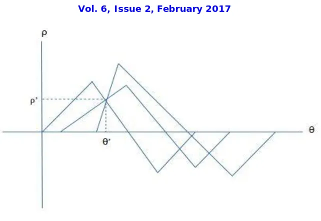
ρ=X*cosθ + Y*sinθ [2]. Here ρ and θ are the parameters of line to be found by Hough transform. Image is captured by
camera which is color image, it is converted to binary feature image using MATLAB functions. When this binary feature image is represented firstly in x-y plane shown in fig. 1.
Fig. 1. Image shown in X-Y plane
Each pixel of image in x-y plane have some x-y co-ordinate value. By putting each x-y co-ordinate value in equation
one, ρ-θ plane is obtained. Suppose a line in present in X-Y plane, each and every point of that line is transformed to
Fig. 2. Image shown in ρ-θ plane
II. RELATEDWORK
Hough Transform have more computations, other line-detection schemes such as gradient-based Hough transform and kernel-based transform. These systems require fewer computations than Hough transform, but they still require a high-end CPU, which is often unavailable in practical applications, or special hardware devices to achieve real-time performance. The gradient-based Hough Transform has been implemented in special hardware, but kernel-based Hough transform, which adopts a link-list data structure, is difficult to implement efficiently in hardware. There has been some research to implement the Hough Transform on special hardware, such as graphic processors, scan line array processors, and pyramid multiprocessors. However, these devices are unsuitable for low-cost embedded systems [2]. One straightforward method to implement Hough Transform is using multipliers. However, multipliers are less available on low-end FPGAs. Hence, some researchers implement Hough transform using a coordinate rotation digital computer (CORDIC) or a simplified CORDIC algorithm such as the multiple sector algorithm. CORDIC is an arithmetic technique developed by Volder to solve trigonometric problems by rotating a vector in small angles until the desired angle is achieved. The CORDIC algorithms for FPGA are surveyed in. CORDIC could implement the Hough transform using only shifters and adders rather than multipliers. FPGA platform is proposed to implement Hough transform by using hybrid-log arithmetic. Distributed arithmetic (DA) architecture is proposed to implement Hough transform with shift–add operations [2]. But it also requires multiple iterations to obtain one in the parameter space. An accumulator-based architecture is proposed. This system gives simulation of Hough transform using locality property on FPGA using Xilinx.
III.XILINXSIMULATION
matrix getting maximum votes for that particular angle are nothing but the final parameters of a line present in an input image.
IV.SYSTEMALGORITHM
1. Initialize all votes to zero
2. Perform voting procedure and store votes in Registers
3. for all feature points (x, y) of input image perform vote algorithm
4. now image can be any where in x-y plane between angles 0° to 90° means for every 0° ≤ θ≤ 90°
5. calculate rho value using equation one
6. Round rho value to integer using equation ρ‘=round(ρ) 7. Let rho value obtained is 670 and index of vote matrix [670,0] will get one vote because angle in loop now is 0°
8. increase vote of ρ, θ value obtained in voting algorithm using equation votes (ρ‘, θ‘) = Votes (ρ, θ) + 1 9. Finally index of vote matrix (ρ‘, θ‘) getting maximum votes are the output of the system
10. Block programming of Verilog is used in simulation code 11. Firstly input and output ports of the system are given
12. Then signal flow direction and data-types of I/O ports are given 13. Registers, wires, global variables and constants variables are defined
14. Cardiac core 4.0 is used to find sine and cosine values of input angles as well as maximum rho value 15. always block is defined which repeat itself at positive edge of system clock
16. All loops used in code are initialized
17. Then voting procedure is given in code and votes are stored in registers
V. EXPERIMENTALRESULTS
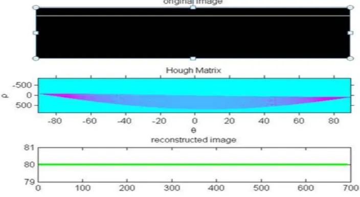
Complete steps of system's code is explained in section IV along with voting algorithm. Firstly system algorithm is simulated in MATLAB R2012a. First image shown in fig. 3 is given as input, Then voting algorithm is performed. Final vote matrix called here as Hough Matrix is shown in second image of fig. 3. Final rho and angle value (ρ‘, θ‘)
obtained from voting algorithm is given further to MATLAB Standard functions for finding lines with exact location in given image. Final output image is constructed with output parameters obtained in voting algorithm, shown in third image of fig.3.
Table one shows MATLAB simulation results, Image shown in fig. 3 is given as input and final rho value obtained is 774 for angle 90°. Third and fourth row gives details computations of voting algorithm.
Parameters Values
ρ Value 774
θ Value 90°
Additions in lac's 2.48
Multiplications in lac's 12.44
Table 1. Computation results
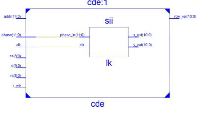
After verifying the voting algorithm of this system in MATLAB it is simulated in Xilinx. Fig. 4 shows schematic diagram of UUT. It shows input ports, system clock, signal flow, output ports and various blocks used in system.
Fig. 4. Schematic diagram
System code is written using Verilog module and it is synthesized. Then implement design operation is performed after that timing constraints are generated. System clock chosen is of 20 ns. Timing details are given in table 2.
Met Constraints Check
Worst Case Slack
Best case achievable
Timing Errors
Timing Score Yes Autotimespec constraints for clock net clk_BUFGP SETUP HOLD 0.392 ns 3.509 ns 0 0
Table 3 gives details about device utilization of this system. This values are taken from synthesis report generated after synthesis of code. Values shown here are used values out of total available devices in XC6SLX45.
Devices Used Values
Slice Registers 516
Slice LUTs 601
LUT-FF pairs 468
Bonded IOBs 13
Buffers 1
Table 2. Device Utilization
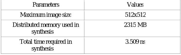
Input binary image obtained from MATLAB prepossessing of size 20x2 is stored first in distributed register bank memory and then voting algorithm is executed in always block of code. System analysis values are given in table 3. Maximum image size that can be processed is of 512x512. Total distributed register bank memory used by this system for input image is of 2315 MB and totla time required in synthesis is 3.509 ns.
Parameters Values
Maximum image size 512x512
Distributed memory used in synthesis
2315 MB
Total time required in synthesis
3.509 ns
Table 3. System analysis
VI.CONCLUSION
Hough transform is used to detect various shapes in an image. Xilinx simulation result is obtained and FPGA can be used to provide real time implementation of Hough transform. This system can process maximum images size of 512x512. Images with complex image size require more Computations and processing time so this system is useful for images with small sizes.
REFERENCES
[1] Lewis Baker,Steven Mills,Tobias anglotz,Carl Rathbone, “Power line detection using Hough transform and line tracing techniques”, IEEE
Conference Publications, 10.1109/IVCNZ.2016.7804438
[2] Zhong-Ho Chen, Alvin W. Y. Su, and Ming-Ting Sun, “Resource-Efficient FPGA Architecture and Implementation of Hough Transform”,
IEEE Transactions on VLSI systems, vol. 20, no. 8, August 2012
[3] Subbiah, A.Rega, “Implementation of Hough Transform Using Resource Efficient FPGA Architecture”, International Journal of Advanced
Information Science and Technology (IJAIST), ISSN: 2319:2682, Vol.14, No.14, June 2013
[4] Jagdish shete, Sunil kore and Vijaykumar S. Kawde, “Pipe-lined VLSI Architecture for CDF (2, 2) Lifting Based 1-D Discrete Wavelet
Transform” , International Journal of Engineering Associates (ISSN: 2320-0804) # 45 / Special Issue -1 (Volume 3) NC- EMPIRES
[5] Karthik Mayasandra, Hanif M. Ladak, Wei Wang, “A Distributed Arithmetic hardware Architecture for Real-Time Hough Transform Based
Segmentation”, 0-7803-8886-0/05/$20.00 2005 IEEE
[6] R. Andraka, “A survey of CORDIC algorithms for FPGA based computers”, in Proc ACM/SIGDA 6th Int. Symp Field Programmable Gate
Arrays, Monterey, pp. 191–200
[7] Costin-Anton Boiangiu, Bogdan Raducanu, “Robust Line Detection Methods”, 9th WSEAS International Conference on Automation and
[8] R. Andraka, “A survey of CORDIC algorithms for FPGA based computers”, in Proc ACM/SIGDA 6th Int. Symp Field Programmable Gate Arrays, Monterey, pp. 191–200
[9] M.-Y. Chern and Y. H. Lu, “Design and Integration of Parallel Hough Transform Chips for High Speed Line Detection”, in Proc. 11th Int.
Conf. Parallel Distrib. Syst. Workshops, 2005, vol. 2, pp. 42–46
[10] O. Djekoune and K. Achour, “Incremental Hough transform: An Improved algorithm for Digital Device Implementation”, Real-Time Imaging,
vol. 10, no. 6, pp. 351–363, 2004
[11] J. D. Bruguera, N. Guil, T. Lang, J. Villalba, and E. L. Zapata, “Cordic based parallel/pipe-lined architecture for the Hough transform”, J. VLSI Signal Process.,vol. 12, no. 3, pp. 207–221
[12] Vijaykumar S. Kawde and Jagdish shete, “Line detection using Hough transform technique with two different approaches”, International