ABSTRACT
HAN, KOOHEE. Field-Driven Reconfigurable Assemblies and Self-Propelling Microbots Engineered from Anisotropic Particles (Under the direction of Dr. Orlin D. Velev).
Colloidal systems of anisotropic particles in external fields represent a rapidly emerging area in soft matter, evoking intense interest due to their unusual interactions, dynamics, and structure
formation abilities. From an engineering perspective, a variety of field-driven dynamic responses can be encoded in the design of anisotropic particles, thereby forming the basis of developing structures with on-demand functionality. Early examples of such structures have shown promise
for making of materials with simple responses, such as one-dimensional contraction and translational motion in a single direction. However, encoding more sophisticated functionalities
into colloidal structures has been challenging.
This dissertation presents engineering strategies to formulate a new class of dynamic structures capable of precise microscale operations. Our approaches are based on using anisotropic
colloidal particles with tailored form factors and surface polarizabilities. To gain fundamental insights into their complex field-driven dynamic behaviors, we focus on particle-particle and
particle-medium interactions at the microscale level. Building upon the identified fundamental breakthroughs, we develop concepts for miniaturized machines that could potentially address critical challenges in science and medicine.
First, we introduce self-reconfiguring microbots made by magnetic assembly and actuation of one-side cobalt coated patchy microcubes. Assemblies of the patchy microcubes can store
energy through magnetic polarization of the cobalt patches and release it by microscale reconfiguration. These reconfiguration patterns are determined by the sequence of the cube orientations within the assemblies. We demonstrate microbot prototypes that can be used to
folding actuation with a gradient field for spatial maneuvering.
We extend the use of the sequence-encoded reconfiguration function of the multi-cube assemblies to make self-propelling microswimmers. Single-hinged “microscallop” assemblies can
be directionally motile when suspended in non-Newtonian fluids and actuated by cyclic time-asymmetric magnetic fields. The field-controlled time-time-asymmetric flapping strokes of the
microscallops create a local viscosity gradient and generate propulsive thrust. We demonstrate that the viscophoretic swimming motility of microscallop assemblies depends not only on the type of time-asymmetric flapping strokes, but also on their geometric length and sequence.
Lastly, we present another class of motile externally powered microdevices that controllably spin about their central axis in AC electric fields. The rational design of these “microspinners” enables the conversion of electrical energy into active rotation. Multiple
electrokinetic mechanisms operating at different frequency ranges can be programmed via the anisotropy of the particle shape and polarizabilities. We demonstrate that the microspinners can
switch their direction of rotation on-demand by changing the frequency of the electric fields. The principles and engineering strategies identified in this dissertation could be extended
to design dynamic structures with more elaborate functions and higher degree of controllability by using more complex particle shapes, compositions, and field parameters. We believe the scientific principles for making such advanced dynamic structures could be used to address a broad range of
© Copyright 2018 by Koohee Han
Field-Driven Reconfigurable Assemblies and Self-Propelling Microbots Engineered from Anisotropic Particles
by Koohee Han
A dissertation submitted to the Graduate Faculty of North Carolina State University
in partial fulfillment of the requirements for the degree of
Doctor of Philosophy
Chemical Engineering
Raleigh, North Carolina 2018
APPROVED BY:
_______________________________ _______________________________ Dr. Orlin D. Velev Dr. Carol K. Hall
Committee Chair
ii
DEDICATION
BIOGRAPHY
Koohee Han was born in Seoul, South Korea to Sang Hyuk Han and Eunhee Lim. He grew up with his older brother Kwanhee Han in Janghowon, a small town in Icheon-si, Kyunggi-do, South
Korea, while attending Janghowon Elementary, Middle, and High School. After obtaining his B.S. in 2011 and M.S. in 2013 in Chemical Engineering from the University of Seoul, Seoul, South
Korea, he joined the Department of Chemical and Biomolecular Engineering at North Carolina State University, Raleigh, NC in Fall 2013. Since joining the group of Prof. Orlin D. Velev in Dec. 2013, his PhD research has focused on understanding the fundamentals behind the dynamic
behaviors of anisotropic colloidal particles in external fields under the guidance of Prof. Velev. During his graduate pursuit, he had an internship in Panel Process and Optics Engineering team of
ACKNOWLEDGMENTS
This work would not have been possible without the help and support of many people. First and foremost, I would like to thank Prof. Orlin D. Velev, who has been an exceptional advisor and a
wonderful role model. He has guided me in the right direction with his enthusiasm, insight, and positive attitude while helping me to seek intellectual curiosity and creativity by providing a lot of
interesting research opportunities.
I respectfully thank Prof. Carol K. Hall, Prof. Jan Genzer, and Prof. Michael D. Dickey, for serving as my committee members and for providing helpful advice throughout my PhD
studies. I am very honored to have such a committee composed of very accomplished scientists who are also very kind and friendly people.
I am grateful to past and present members of the Velev research group. I appreciate Prof. Bhuvnesh Bharti who shared his knowledge and research experience with me when I first joined the group. I thank Dr. C. Wyatt Shields IV and Dr. Ugonna Ohiri who have been an excellent
colleague and collaborator to work with. I thank Dr. Fuduo Ma who taught me his expertise in AC electrokinetics.
I would like to thank the Research Triangle MRSEC for the financial support and for the education and outreach opportunities throughout my PhD studies. I sincerely appreciate Mrs. Amy Alexander for her kind help with taking care of all administrative services of MRSEC. I would
also like to thank the staff members, Mrs. Sandra Bailey, Mrs. Angela Efimenko, Mrs. Joan O’Sullivan and Mr. Mike Mantini, from our department for their kind help and support.
TABLE OF CONTENTS
LIST OF TABLES ... viii
LIST OF FIGURES ... ix
Chapter 1 – Introduction: Field-Directed Manipulation and Control of Colloidal Systems ... 1
1.1Introduction: from Static to Dynamic Colloidal Systems ... 2
1.2Anisotropic Particles for Colloidal Systems ... 3
1.3Field-Directed Assembly of Colloidal Systems ... 9
1.3.1 Magnetic Field-Driven Reconfigurable Assemblies ... 13
1.3.2 Electric Field-Driven Reconfigurable Assemblies ... 16
1.4Field Powered Self-Propelling Particles ... 22
1.4.1 Magnetic Field-Driven Self-Propelling Particles ... 28
1.4.2 Electric Field-Driven Self-Propelling Particles ... 32
1.5Layout of this dissertation ... 37
1.6References ... 38
Chapter 2 – Sequence-Encoded Reconfiruable Assemblies in Magnetic Fields ... 49
2.1Introduction ... 50
2.2Materials and Methods ... 51
2.2.1 Particle Fabrication ... 51
2.2.2 Experimental Setup ... 51
2.2.3 Numerical Simulation... 52
2.3Results and Discussion ... 53
2.3.1 Magnetic Field Driven Assembly of Multi-Cube Clusters ... 53
2.3.3 Configurational Interaction of Cube Doublets ... 56
2.3.4 Cluster Folding Rules: Identifying Reversibly Reconfigurable Cube Triplets ... 60
2.3.5 Sequence-Controlled Assembly of Multi-Cube Clusters ... 62
2.3.6 Sequence-Encoded Dynamic Reconfiguration of Cube Quadruplets ... 64
2.3.7 Examples of Microbots and Colloidal Origami with Sequence-Encoded Function ... 66
2.4Conclusion ... 68
2.5Acknowledgements ... 69
2.6References ... 70
Chapter 3 – Active Swimming of Self-Assembled Microbots in Non-Newtonian Fluids ... 72
3.1Introduction ... 73
3.2Materials and methods ... 74
3.2.1 Materials ... 74
3.2.2 Experimental Setup ... 75
3.2.3 Numerical Simulation... 76
3.3Results and Discussion ... 76
3.3.1 Self-Propulsion Principle of Microscallops ... 76
3.3.2 Active Swimming Modes of Microscallops ... 80
3.3.3 Effects of Time-Asymmetric Flapping Strokes on Swimming Dynamics ... 81
3.3.4 Effects of Geometric Designs on Swimming Dynamics ... 84
3.4Conclusions ... 87
3.5Acknowledgements ... 88
Chapter 4 – Active Rotation of Engineered Particles Powered by AC Electric Fields ... 91
4.1Introduction ... 92
4.2Materials and methods ... 94
4.2.1 Particle Fabrication ... 94
4.2.2 Experimental Setup ... 95
4.2.3 Ionic Content of Deionized Water Exposed to the Atmosphere ... 96
4.3Results and discussion... 97
4.3.1 Electrokinetic Rotation of Non-Patchy Microspinners ... 97
4.3.2 Electrokinetic Rotation of Patchy Microspinners ... 100
4.4Conclusions ... 106
4.5Acknowledgements ... 107
4.6References ... 108
Chapter 5 – Summary and Outlook ... 111
5.1Summary ... 112
5.2Future Outlook ... 114
LIST OF TABLES
LIST OF FIGURES
Figure 1.1: Conceptual framework of representative types of anisotropic particles. Key anisotropy attributes of particles are vertically presented where each row
shows homologous series of anisotropic particles. Reproduced with
permission.[31] Copyright 2007, Nature Publishing Group. ... 4
Figure 1.2: Representative methods for the fabrication of engineered anisotropic particles. (a) Fabrication of asymmetric helical structures by glancing angle deposition (GLAD) and substrate rotation. Metal vapor is deposited onto a monolayer of
spherical particles on a motorized substrate at an angle, 𝛼. (b) Fabrication of
bimetallic rods using anodic aluminum oxide (AAO) template-assisted electrodeposition. After electrodeposition, the AAO template is removed to
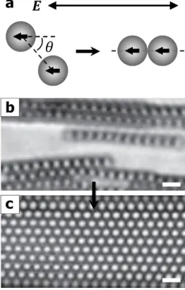
obtain, in this case, Au/Pt bimetallic rods. (c) Fabrication of anisotropic patchy particles using alignment photolithography and metal deposition. ... 7 Figure 1.3: External field-driven assembly of isotropic particles. (a) Electric dipole
polarization of micron-size spherical particles by application of an external alternating current (AC) electric field. Once polarized, two particles
self-assemble into a linear chain (i.e., 𝜃→ 0) to minimize their dipolar interaction
potential. (b) Assembly of linear chains of particles by application of a horizontal AC electric field. (c) Formation of a 2D colloidal crystal from multiple chains by continuous application of the external field. Scale bar: 3
µm. Reproduced with permission.[88] Copyright 2006, Royal Society of
Figure 1.4: External field-driven assembly of anisotropic particles. (a) A snapshot (left) and a schematic illustration (right) of a crystal structure assembled from hexnuts in a horizontal AC electric field. Scale bar: 5 µm. Reproduced with
permission.[94] Copyright 2008, American Chemical Society. (b) A snapshot (left) and a schematic illustration (right) of staggered chains assembled from
metallo-dielectric Janus particles in a horizontal AC electric field. Strong electric polarization (white arrow) of the metallic patches (black hemisphere) leads to the formation of staggered chains where the metallic patches are
connected in series along the center of the chains. These staggered chains can be further assembled into a crystal structure resulting from the interactions
between polarized dielectric bodies (grey hemisphere; black arrow indicates weak electric polarization). Scale bar: 5 µm. Reproduced with permission.[95]
Copyright 2008, American Chemical Society. ... 12
Figure 1.5: Magnetic field-driven reconfiguration of assemblies of Janus particles. (a–b) Assembly of Janus particles in a horizontal magnetic field: (a) the formation of
linear chains of Janus particles by application of the magnetic field and (b) reconfiguration of the chains by removal of the field. The inset in (b) displays the disassembled Janus particles after demagnetization. Reproduced with
permission.[102] Copyright 2009, Royal Society of Chemistry. (c–d) Assembly of Janus particles in a rotating magnetic field: (c) the formation of a monolayer
clusters by increasing the strength of the rotating field to 300 Gauss. Scale bar:
5 µm. Reproduced with permission.[105] Copyright 2015, Wiley. ... 14 Figure 1.6: Linker-mediated assembly of magnetic particles into flexible filaments. (a–d)
Assembly of linear chains from micron-size magnetic particles connected by DNA linkers. Depending on the length of the DNA linkers and the field
strength, the assembled chains were: (a) rigid (564 bp, 140 Gauss), (b) semi-flexible (2000 bp, 140 Gauss), (c) semi-flexible (4000 bp, 19 Gauss), and (d) depleted semi-flexible; the depletion of long flexible linkers (8000 bp) by a
strong magnetic field (140 Gauss) resulted in a semi-flexible chain.
Reproduced with permission.[106] Copyright 2014, American Chemical Society.
(e–f) Assembly of ultra-flexible filaments from magnetic nanoparticles connected by capillary bridging: (e) formation of flexible linear filaments of magnetic nanoparticles by application of a horizontal magnetic field, (f)
assembled filaments were fractured locally with a sharp stylus, and (g) self-repaired by the reintroduction of the magnetic field. Reproduced with
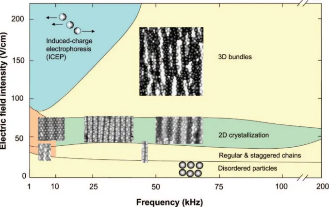
permission.[108] Copyright 2015, Nature Publishing Group. ... 16 Figure 1.7: A variety of assembly patterns formed from metallo-dielectric Janus particles
in an AC electric field depending on the field strength and frequency.
Reproduced with permission.[95] Copyright 2008, American Chemical Society. ... 17 Figure 1.8: Electric field-directed control of assembly patterns of anisotropic particles. (a–
Scale bar: 3 µm. Reproduced with permission.[110] Copyright 2014, Royal
Society of Chemistry. (c–d) Assembly of symmetric dimers under a vertical electric field: (c) formation of close-packed standing dimers (perpendicular to
the surface) at ~6 kHz where each dimer viewed from above appears as a circle in the assembled structure because its long axis aligns in the applied field
direction and (d) reconfiguration of packed standing dimers into close-packed lying dimers (parallel to the surface) at ~0.6 kHz. Scale bar: 3 µm.
Reproduced with permission.[111] Copyright 2012, Wiley. ... 19
Figure 1.9: Electric field-driven directional reconfiguration of assemblies of anisotropic particles. (a–b) Contraction of a chain of Janus spheres in overlapping
magnetic and AC electric fields: (a) formation of a staggered chain from Janus spheres in an AC electric field and (b) contraction of the staggered chain into a double chain (L1 > L2) upon subsequent application of a parallel magnetic
field. Scale bar: 10 µm. Reproduced with permission.[119] Copyright 2013, American Chemical Society. (c-d) Reversible elongation and contraction of an
assembly of Janus ellipsoids by toggling an external AC electric field: (c) self-assembly of an ordered fiber (OrF) structure with a four-particle unit cell (a represents the unit cell size) from Janus ellipsoids at a salt concentration of 5
mM and (d) reconfiguration of the OrF structure into a chain-link (CL)
structure with elongation of the unit cell from a to 2a upon application of an external AC electric field. The CL structure snapped back into the OrF
structure upon removal of the field. Scale bar: 3 µm. Reproduced with
Figure 1.10: Schematic example of a field-powered, self-propelling particle with
representative design elements. A hypothetical engineered particle may self-propel by transducing energy, in this case, from an external electric field along
the x-axis (black dotted lines), into a local gradient. A magnetic patch can be used as an additional means of control (e.g., to impart torque) for steering, in
this case, via an external magnetic field that rotates around the x/y-plane (blue lines). The bulk material of the particle can be modified (e.g., doped to form a p-n semiconductor junction) to rectify an external electric field, as in this case,
towards a microdiode particle. A sensor connected to the circuit can be used to control the motion of the particle (e.g., turning on or off the diode) by
responding to external stimuli (e.g., light). Bioaffinity tags (e.g., antibodies or aptamers), as shown along the front of the particle, can be used to capture bioanalytes in solution, allowing the particle to serve as a self-propelling
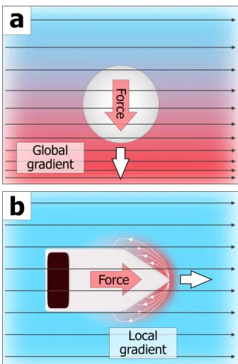
biosensor. ... 23 Figure 1.11: Schematic comparison of the origin of motion of a non-active (global field
gradient-driven) and an active (local field gradient-driven) particle in an external field. (a) A non-active, spherical particle with tri-axial symmetry is pulled by a positive gradient toward the field maximum (downward). (b) An
engineered active particle moves itself rightward by transducing energy from a uniform external field to generate a local field gradient. The gradient is
indicated by a change in color from blue to red, which is global for (a) and
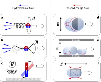
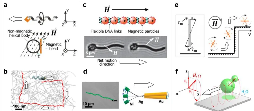
Figure 1.12: Methods for powering the active propulsion of particles by magnetic and electric fields. (a-c) Asymmetric hydrodynamic flows generated by external magnetic fields. (a) Axial propulsion of a rigid helical body by a rotating
magnetic field. (b) Traveling-wave propulsion of a flexible magnetic flagellum by an oscillating magnetic field. (c) Surface-assisted propulsion of a magnetic
rod by a rotating magnetic field. (d-f) Asymmetric induced-charge flows generated by external AC electric fields. (d) Induced-charge electroosmosis of a metallo-dielectric Janus particle. In a horizontal AC electric field, the more
strongly polarizable metallic side (black hemisphere) generates a stronger electroosmotic slip (red arrows), resulting in motion toward the dielectric side
(gray hemisphere). (e) Asymmetric surface electrohydrodynamic (EHD) flows of a fused particle dimer. In a vertical AC electric field, the dimer experiences surface EHD flows adjacent to the conducting surface (red arrows).
Unbalanced EHD flows around the dimer leads to motion, in this case, in the direction of the smaller particle. (f) Self-rectified electroosmosis of a diode
particle. The embedded diode rectifies an external AC electric field into a local DC electric field, leading to self-electroosmotic flows (red arrows). ... 28 Figure 1.13: Representative examples of magnetically powered self-propelling particles.
(a-b) Helical propulsion. (a) Artificial bacterial flagellum (ABF) consisting of a magnetic head bound to a non-magnetic helical tail. In a continuously rotating
swimmer passing through a gelatinous network. Adapted with permission.[167]
Copyright 2014 American Chemical Society. (c-d) Traveling-wave propulsion. (c) A flexible artificial flagellum consisting of a chain of magnetic particles
connected by flexible DNA linkages. Under an oscillating magnetic field, the flexible magnetic tail that is attached to a red blood cell moves in the direction
of its free end by a field-induced undulating motion. Adapted with
permission.[168] Copyright 2005 Nature Publishing Group. (d) A magnetic nanowire swimmer consisting of an Au head and Ni tail is linked by a flexible
Ag bridge. Under a rotating magnetic field, the flexible bridge allows the tail to freely rotate and as the head rotates at a different amplitude, the breaking of the
symmetry of the system leads to propulsion. Reprinted with permission.[185] Copyright 2010 American Chemical Society. (e-f) Surface-assisted propulsion. (e) A rigid Ni nanowire near a solid surface in water. When subjected to a
rotating magnetic field, the asymmetric boundary condition around the particle, as shown in the inset, allows the particle to propel along the wall. Reprinted
with permission.[152] Copyright 2010 American Chemical Society. (f) A paramagnetic, asymmetric dimer on a glass plate. Under a magnetic field precessing about the y-axis, the dimer propels along the x-axis due to the
periodic rotation of the small lobe in the x/z-plane (i.e., about the y-axis).
Reprinted with permission.[176] Copyright 2008 American Physical Society. ... 31
double layer for one half cycle of an AC electric field. Under a horizontal AC
electric field with a low frequency (e.g., 0.1–10 kHz), a stronger slip from ICEO around the Au side drives the JP to propel in the direction of the
polystyrene (PS) side. Adapted with permission.[158] Copyright 2008 American Physical Society. (b) Self-dielectrophoresis of a JP. Under a vertical electric
field at a high frequency (i.e., > 100 kHz), the JP travels with its Au side facing forward due to strong induced field gradients between the Au hemisphere and the conducting substrate (bottom, right inset). Adapted with permission.[188]
Copyright 2016 American Chemical Society. (c-d) Asymmetric surface electrohydrodynamic (EHD) flows for particle self-propulsion. (c) An
asymmetric PS dimer self-propels by asymmetric EHD flows in a vertical electric field, in this case, at frequencies between 1.4 and 6.0 kHz. The top schematic illustrates a dumbbell model where two spheres, A and B, are
connected by an imaginary rod. The dimer moves toward the B end since the B particle generates stronger attractive EHD flows. Adapted with permission.[161]
Copyright 2015 American Physical Society. (d) Circular motion of a L-shaped particle overlaid with its trajectory (left). A schematic of the template used to assemble the L-shaped particle (right). Adapted with permission.[192] Copyright
2017 Royal Society of Chemistry. (e-f) Self-rectified electrophoretic motion. (e) A millimeter-sized diode self-propels on a liquid-air interface due to an
Group. (f) Nanosized-diode self-propulsion. A SEM image (left) and a
schematic diagram (right) of a Cd/Polypyrrole nanowire diode propelling away from its Cd end. Adapted with permission.[195] Copyright 2010 American
Chemical Society. ... 36 Figure 2.1: Schematic of the experimental setup used to assemble and manipulate the
patchy microcubes. A uniform magnetic field was generated by a collinear pair of electromagnets (1 and 2) and a magnetic field gradient was imposed by a
single electromagnet (3). ... 52
Figure 2.2: Example of the assembly of patchy microcubes under a uniform magnetic field. (a) Randomly dispersed microcubes, (b) magnetic polarization of the Co
patches in the direction of the applied magnetic field, leading to either A or B cube orientations, and (c) formation of multi-cube clusters that retain such A or B orientations. The superimposed yellow lines in the experimental micrographs
denote the location of the magnetic patches. Scale bar = 20 μm. ... 53 Figure 2.3: (a) An image from an optical microscope, (b) An image from an SEM and (c)
An EDS recording overlaid on the image shown in (b) (green color indicates
the presence of Co) of an assembled chain of patchy cubes. Scale bar = 20 μm. ... 54
Figure 2.4: Magnetic hysteresis curve of a collection of dried Co-coated patchy
microcubes. Measurements and schematics illustrate: (a) The initial state of randomly dispersed microcubes, (b) The saturated magnetization state of the
microcubes, (c) The saturated residual magnetization state (Mrs) of the
microcubes and (d) The relative residual magnetization (Mr/Mrs, where Mr is
initially applied magnetic field, which is in the range of the field strengths used
in our experiments. ... 55 Figure 2.5: Magnetic field driven self-reconfiguration of an assembled cluster. (a)
Example of a linear chain of patchy microcubes formed upon the application of uniform magnetic field. (b) Reversible self-reconfiguration of the linear chain
in (a) into a structure of two closed loops upon removing the applied field. The superimposed yellow lines denote the magnetic patches. scale bar: 20 μm. ... 56
Figure 2.6: Schematics of the two basic unit doublets, AB and AA, which correspond to assembled particles on the same side or opposite sides of the assembled magnetic films, respectively. Upon removal of an external magnetic field, AB
in (a) shows no reconfiguration while AA in (b) self-folds to minimize the
magnetic interaction energy between the metallic patches. ... 57 Figure 2.7: Calculation of the dipole-dipole interaction energy for patchy microcube
doublets as a function of bending angle in the absence of an external magnetic field. The black solid line represents the trajectory of the spontaneous
self-folding motion of an AA doublet into a C configuration (where the global minimum occurs at δ = 0°). The grey dashed line reveals that the AB doublet
favors its initial configuration of the local minimum at δ = 180°. The top right
inset (indicating the key parameters of Eq. 2.1) illustrates the interaction
between two dipoles of finite length 2l in terms of the unit vector of each
dipole, 𝑛i and 𝑛j, and the position vector 𝑟ij between 𝑛i and 𝑛j, where 𝛼 is the
angle between 𝑛i and 𝑛j, 𝛽 is the angle between 𝑛i and 𝑟ij, 𝛾 is the angle
inset (indicating the key parameters of Eq. 2.2, an equivalent form of Eq. 2.1)
illustrates the interaction between two dipoles of finite length 2l in terms of the
position vector between magnetic charges, 𝑟13, 𝑟14, 𝑟23 and 𝑟24, which are separately distributed along each Co patch. ... 59
Figure 2.8: Reconfiguration patterns of short chains of microcubes driven by dipole-field and residual dipole-dipole interactions. (a) Change in the magnetic dipolar
energy per microcube during the reconfiguration process as a function of the interdipolar angle δ, the angle between planes of magnetic patches on adjacent
microcubes, adapting self-folding toward the ground state. The inset illustrates
the interaction between two dipoles of finite length 2l in terms of the unit
vector of each dipole, 𝑛i and 𝑛j, and the position vector 𝑟ij between 𝑛i and 𝑛j. (b-j) Snapshots of the reconfiguration patterns intrinsic to AA, AAA and AAB
sequences. After the applied field is removed, the microcube chains self-fold (b-c, e-f and h-i) until (i) a ground state configuration is attained (e.g., c), (ii) a metastable structure is formed (e.g., f) or (iii) a sterically restricted
conformation is attained (e.g., i). When the external field is imposed again, (i) the ground state configuration C is retained (e.g., d), (ii) the metastable AAA
structure usually reconfigures into AC (e.g., g), (iii) and the partially wrapped structure AAB re-attains its initial stretched state (e.g., j). Scale bar = 20 µm. ... 61
Figure 2.9: Chain reorientation techniques for reprogramming the relative sequence of a microbot assembly (BAA→BBA→ABB). The first conversion (i.e., BAA→
BBA) is achieved by a 180° z-axis rotation via gradually switching the
→ABB) is achieved by a 180° y-axis rotation via rapidly switching the
magnetic field from +0.8 kA/m to -0.8 kA/m. The numbers 1, 2 and 3 on the
schematic are correspondingly reoriented along with the cubes during the
conversions. Scale bar = 10 μm. ... 62
Figure 2.10: Chain reorientation technique to program the sequence of a microbot. A BBA chain is reoriented into an ABB chain by a y-axis rotation via rapidly changing the magnetic field strength from -0.8 kA/m to +0.8 kA/m. The continuous field
application then leads to the assembly of an ABBA chain from the newly oriented ABB chain and a single cube with an “A” orientation. Scale bar = 10 μm. ... 63
Figure 2.11: Examples of dynamic reconfiguration of chain sequences comprising four microcubes. (a) Snapshots of field-on and -off states of the four particle
colloidal isomers, i.e., ABBA and BBAA. Scale bar = 20 µm. (b) Dependence of folding rate measured for the initial 0.5 s of the ABBA microcube sequence on
the applied magnetic field strength after the field is removed. The folding rate is linearly dependent on the square of the strength of initially applied magnetic field. The error bars correspond to the standard deviation of the folding rate per
the square of the field strength from 5 different ABBA structures. ... 64 Figure 2.12: The kinetics of the self-reconfiguration of four particle clusters expressed by
mean interparticle (≡ interdipolar) angle δ. Changes in the interdipolar angle
for clusters with an ABBA, ABBB and BBAA sequence from two consecutive
Figure 2.13: Microcube assemblies as prototypes of microbots for transporting cells and as colloidal origami. (a-e) Snapshots of a microbot comprising six microcubes (BABBAB) used for transporting a yeast cell. (a) Spatial migration of the
assembly in its open state under uniform external magnetic field with longitudinally imposed gradient. (b) The microcube chain is brought to the
yeast cell by attraction along the gradient. (c) The cluster self-closes upon removing the uniform field, which results in the capture of the yeast cell. (d) The microbot is transported to the target location by a magnetic gradient force.
(e), Finally, the cell is released by re-activating the uniform magnetic field. (f-j) Distribution of magnetic field intensity around the BABBAB assembly during each stage of manipulation shown in (a-e), as calculated by COMSOLTM
Multiphysics. (k-l) Snapshots of a repeatedly self-reconfigurable multi-cube chain as an example of programmable colloidal origami. Scale bars in (a) and
(k) = 20 µm. ... 67 Figure 3.1: Shear-rate dependent viscosity data of water and 0.01wt% xanthan gum
solution. Water exhibited constant viscosity regardless of shear rate. The xanthan gum solution exhibited a lower viscosity at a high shear rate revealing shear-thinning non-Newtonian rheological behavior. ... 75
Figure 3.2: (a) Schematic of the experimental setup, comprising an assembly cell and a collinear pair of electromagnetic coils connected to a function generator. (b-d)
slow decrease in the field strength; (d) Time asymmetrical slow increase and
sudden increase in the field strength. ... 76 Figure 3.3: Self-propulsion mechanism of a magnetically reconfigurable self-assembled
microscallop based on cyclic time-asymmetric reciprocal strokes in non-Newtonian fluids. (a) A schematic illustration and a snapshot of a scallop-like
assembled cluster exhibiting the closing stroke (i→ii) and the opening stroke (ii→i) by application and removal of an external magnetic field, respectively. Scale bar: 10 µm. The xy-coordinate plane is presented in the snapshot of (ai).
(b) A diagram depicting the change in the strength of a magnetic field for slow opening and rapid opening stroke. (c-d) Displacement of the central hinge (red circle) of the self-assembled microscallop along y-axis under the slow opening
and rapid closing stroke by the applied magnetic field in (b): (c) linear displacement in a Newtonian fluid; (d) nonlinear displacement in a
non-Newtonian fluid. ... 78
Figure 3.4: Tracking analysis on displacement of the central hinge of the 4-cube
symmetric cluster as a function of the angle of closing stroke for strokes in NF
(grey line), slow strokes in nNF (blue line) and rapid stroke in nNF (red circle; net displacement). Note: nF represents Newtonian fluid (water in this case);
nNF represents non-Newtonian fluid (shear-thinning fluid in this case). ... 79
Figure 3.5: Directional active swimming modes of self-assembled microscallops. (a) No net displacement of a 10-cube cluster and a 4-cube cluster under a
Both the (ii) 10-cube and (iii) 4-cube clusters reveal no net displacement after
10 cycles of the time-symmetric stroke. (b-c) Net displacement of the 10-cube and 4-cube clusters under time-asymmetric reciprocal actuations: (bi) rapid
opening & slow opening strokes; (ci) slow opening & rapid opening strokes. A snapshot of the 10-cube cluster overlaid with 5 frames at an interval of 1 sec.
reveals the net (bii) upward and (cii) downward displacement under the applied magnetic field in (bi) and (ci), respectively. A snapshot of the 4-cube cluster overlaid with 5 frames at an interval of 4 sec. reveals the net (biii)
downward and (ciii) upward displacement under the applied magnetic field in (bi) and (ci), respectively. Duty cycle of the signal in (ai), (bi), and (ci): 1 sec. Scale bar: 10 µm. ... 81
Figure 3.6: The effect of time-asymmetric strokes on the net displacement of a long cluster. (a) No net displacement of a cluster with long flapping arms because
of lack of local viscosity gradient. The diagram in (i) depicts the change in the strength of a magnetic field for time-symmetric actuation. Schematic
illustrations of the long cluster with a local viscosity distribution during the (ii) opening and (iii) closing stroke under the applied magnetic field in (i). (b-c) Net displacement of the cluster because of a local viscosity gradient induced
by a rapid stroke. A diagram depicting the change in the strength of a magnetic field for time-asymmetric actuation: (bi) rapid opening & slow closing strokes;
opening strokes under the applied magnetic field in (bi); during the (cii) rapid
closing and (ciii) slow opening strokes under the applied magnetic field in (ci). ... 83 Figure 3.7: Tracking analysis on net displacement of the central hinge of the 10-cube
cluster as a function of time for the applied signals in Figure 3.6ai, bi and ci. Duty cycle of the signal in (ai), (bi), and (ci): 1 sec. ... 84
Figure 3.8: Tracking analysis on displacement of the central hinge of the 4-cube (light red) and 10-cube (light blue) clusters during the slow opening (0−0.8 s) followed by rapid closing (0.8−1.0 s) stroke. For both 4-cube and 10-cube clusters, the
central hinge moves downward under the slow opening stroke and then upward under the followed rapid closing stroke while the 4-cube and 10-cube clusters show net upward and downward displacement, respectively... 85
Figure 3.9: The effect of the cluster length on the direction of net displacement. (a-b) Integrated area of numerically simulated high shear rate region (> 30 s-1
calculated by ANSYS; represented by the green color in the insets) around the (a) 4-cube and (b) 10-cube clusters over the rapid closing stroke (0.8−1.0 s).
As shown in the insets, a snapshot of ANSYS simulation reveals the
generation of an instantaneous high shear rate (the green color) induced by the stroke. A top scallop and a bottom scallop are represented by white arms and
grey arms, respectively, in the insets. These coupled scallops concurrently contribute to generate a high shear rate region where the top and bottom
Figure 4.1: Electrically switchable rotation of supercolloidal spinners. (a) Schematic illustration of a particle microspinner consisting of a transparent polymer body (shown in gray) and a gold patch along the distal end of each of its three arms.
(b) Micrograph of three particle spinners rotating in a vertical electric field (right). Note: the orientation of the spinner in (a) is flipped and mirrored; the correct chirality is shown in (b), whereby the metallic patches face downward. ... 93
Figure 4.2: Microspinner fabrication. (a) UV light selectively exposes spin-coated photoresist through a patterned photomask. (b) Particles are obtained after
washing off uncross-linked photoresist. (c) A scanning electron microscope (SEM) image of anisotropically shaped particles after their removal from the
substrate. (d) While still on the wafer, the formed particles can be coated with a second layer of photoresist, where alignment photolithography is used to create exposed regions along the tops of the particles in discrete regions for
metal deposition. (e) Particles with metallic patches are recovered by removal of the second layer of photoresist. (f) A SEM image of the anisotropic patchy particles before removal from the substrate. ... 95
Figure 4.3: Schematic of the experimental setup used to investigate the rotation of the spinners, powered by a vertical AC electric field between the ITO-coated
slides. ... 96 Figure 4.4: Rotation dynamics data for non-patchy polymer microspinners. (a) Angular
speed of non-patchy microspinners as a function of E2 at 2.0 kHz; positive values indicate clockwise rotation. (b) Angular speed of non-patchy
6.4x10⁵ V2/cm2). (c) Two non-patchy microspinners lock at low field strengths
(E2 = 1.6x10⁴ V2/cm2) and at 2 kHz. Microspinners disassemble and separately rotate at high electric field strengths (E2 = 6.4x10⁵ V2/cm2). ... 98
Figure 4.5: Locking and unlocking behaviors of two non-patchy microspinners. The microspinners lock at low field strengths (E2 = 1.6x10⁴ V2/cm2) and at 2 kHz.
Microspinners disassemble and separately rotate at high electric field strengths (E2 = 6.4x10⁵ V2/cm2). ... 100 Figure 4.6: Schematic of the effect of the electric field frequency on the direction of
particle rotation, where the direction of motion of each particle section is indicated with a black arrow; flow lines (blue and red) are hypothesized. Thus,
particle spinners display four modes of rotation, whereby motion occurs due to (in order of increasing frequency): EHD flows, reversed EHD flows, ICEP,
and sDEP. ... 101
Figure 4.7: Rotation dynamics of patchy metallodielectric microspinners. [Top] Schematics display the direction of particle rotation (clockwise and
anti-clockwise rotations are indicated by red and blue arrows, respectively).
[Middle] Angular speed of patchy microspinners as a function of electric field frequency (at a constant E2 = 6.4x10⁵ V2/cm2); positive values indicate
clockwise rotation. Theoretical trend lines are fitted to the experimental results (symbols) with Eqn. (1) for EHD (solid black line), Eqn. (2) for ICEP (red
line), and Eqn. (3) for sDEP (blue line). The dipolophoresis (DIP) angular velocity (green line) is obtained by summing the ICEP and sDEP
the sum of the DIP and EHD contributions. [Bottom] Expanded view of the
graph above, displaying values between 2 and 500 kHz. ... 103 Figure 5.1: Schematics of expected assembly and disassembly behaviors of two-side
coated microcubes. (a) Dispersed non-magnetized cubes and (b) Formation of rigid crosslinked lattices. Remote magnetization and demagnetization enable
the transition between the state (a) and (b). ... 115
Figure 5.2: (a) Schematic and (b) snapshot of the bending of an anionic hydrogel in a global DC electric field. The hydrogel bending is attributed to the osmotic
pressure difference (π1 > π2) by electrophoretic migration of mobile cations
toward the cathode in the global DC electric field. The schematic in (a)
reproduced with permission.[5] Copyright 2016, Elsevier. The snapshot in (b) is
reproduced with permission.[6] Copyright 2012, Royal Society of Chemistry. .... 116 Figure 5.3: Bending of anionic hydrogels by remotely powered and controlled diodes in a
global AC electric field. (a) Experimental setup depicting a diode-directed
hydrogel bending system. The diode rectifies the global AC field into a local DC field, thereby inducing hydrogel bending. (b) Hydrogel bending from the
linear to zigzag pattern by three externally powered diodes. (c) Light-responsive hydrogel bending using opposing photodiodes. Selective light
illumination controls the direction of hydrogel bending. Schematics on the right-side illustrate the dependence of hydrogel bending on the diode
Chapter 1
Introduction: Field-Directed Manipulation and Control of Colloidal
Systems*
1.1 Introduction: from Static to Dynamic Colloidal Systems
Colloidal systems, by definition, represent a multiphase mixture within which the dispersed phase is distributed in the continuous phase (e.g., solid particles in a liquid medium).[1] The
classifications of colloidal systems are summarized in Table 1.1. depending on types of dispersed and continuous phases.[2] As colloidal systems are highly relevant to our everyday lives (Table
1.1), many different aspects of the field of colloid science have been explored. The interactions between the components of a dispersed phase as well as between the dispersed and the continuous phase play a particularly important role in determining the function of a colloidal system.[3–9] For
example, when particles in solution are subjected to a net attractive force (e.g., attractive capillary forces during the evaporation of the solvent), they self-assemble into a crystalline structure,[10–12]
termed a colloidal crystal.[13–16] Such colloidal assembly techniques have been widely used to generate hierarchically ordered structures from a variety of building blocks ranging in size from molecular to macroscopic.[17–22] While these self-assembled structures have shown promise for a
wide range of potential applications such as optics (e.g., photonic crystals) and electronics (e.g., electrodes),[23–30] their practical use has been limited mainly because of their "static" structure.
Table 1.1: Classifications of colloidal systems in everyday use depending on the nature of the dispersed and continuous phases.[2]
Colloidal systems Dispersed phase
Gas Liquid Solid
Continuous phase (medium)
Gas n/a Liquid aerosol
(ex: hairspray)
Solid aerosol (ex: smoke)
Liquid Foam
(ex: whipped cream)
Emulsion (ex: milk)
Sol (ex: paint)
Solid Solid foam
(ex: Styrofoam)
Gel (ex: jelly)
The assembly of "dynamic" colloidal systems for the fabrication of structures with complex
on-demand functionality is an emerging topic of intense science interest. In contrast to static colloidal systems stabilized in a global equilibrium state, dynamic colloidal systems involve the
transition between local equilibrium states or remain out-of-equilibrium. The former and latter describe reconfigurable structures and active (or self-propelling) structures, respectively. The
focus of this dissertation is to investigate the dynamic behaviors of anisotropic colloidal particles powered by external fields and stimuli. An experimental system was designed based on the following parameters: 1) Phases—solid particles dispersed in a liquid medium were considered as
a model system. Solid particles can move though the liquid medium in a reasonable time scale (i.e., too slow in a solid medium; too fast in a gas medium), and do not significantly change their
size and shape while interacting with each other; 2) Size—approximately 10 µm particles were used to minimize the undesired effect of thermal Brownian motion and facilitate observing their dynamic behaviors in real time using an optical microscope; 3) External stimuli—external
magnetic and electric fields were used as a means to power and control colloidal particles. Dynamic responses of the particles were remotely and precisely tuned using parameters such as
field direction, frequency, and strength.
1.2 Anisotropic Particles for Colloidal Systems
The advances in micro- and nanofabrication have made the creation of particles with extraordinary complexity a reality. The conceptual framework of anisotropic particles presented by Glotzer and Solomon (Figure 1.1)[31] has helped many researchers to develop new, sophisticated methods to
stimuli depending on their design elements such as shape, polarizability and surface functionality.
These elements may allow the particles to function as complex structures such as microbots, microswimmers, and microdevices.
Figure 1.1: Conceptual framework of representative types of anisotropic particles. Key anisotropy attributes of particles are vertically presented where each row shows homologous series of anisotropic particles. Reproduced with permission.[31] Copyright 2007, Nature Publishing Group.
The simplest type of an anisotropic particle is the Janus particle, where one half is physically and/or chemically disparate from the other.[32,33] Metallo-dielectric Janus spheres can
plane.[35] Pawar and Kretzschmar modified this technique by positioning the monolayer of particles
at an angle from the metal source (non-perpendicular) to produce patchy particles[36] in a method commonly referred to as glancing angle deposition (GLAD).[37] By this technique, the patch
geometry is determined by the angle of vapor incidence and the shadow effects by neighboring particles. Once made, selective chemical modifications can be applied to the metallic side or the
non-metallic side to render the particles, for example, biofunctional.[38,39]
Inspired by the design of the helical flagella of some types of bacteria (e.g., E. coli), several methods have been developed to fabricate particles with helical structures, including GLAD,
self-scrolling of thin films and direct laser writing (DLW).[40] GLAD has been shown to produce large numbers of helical structures with high uniformity.[37,41] A monolayer of silica spheres supported
on a solid substrate acts as a seed layer, where the surface of each sphere serves as a nucleation site. After mounting the seed layer at a sharp, glancing angle from the vapor source (e.g., 𝛼 ≈ 85°),
the substrate continuously rotates with respect to the incoming vapor flux of a magnetic material to allow for the growth of a magnetic helical pillar off of each particle (Figure 1.2a).[42] The
chirality and pitch of the helical structures are adjustable by changing the direction and speed of rotation. Self-scrolling method[43] has also been used to produce helical shaped structures, whereby
conventional thin-film deposition was used to make the base material and a magnetic head was attached to one end using e-beam lithography.[44] Here, a 2D multilayer of monocrystalline thin
films was rolled along their crystalline direction into a 3D helical tail. DLW[45] is another method used to fabricate helical structures. This method is based on 3D laser lithography and allows for the fabrication of arbitrary 3D shapes.[46]
electrodeposition (TAE)[47,48] and by soft lithography.[49] AAO TAE has been used to fabricate
multi-block rods, the most popular of which is the Au/Pt catalytic nanomotor, which propels by decomposition of hydrogen peroxide.[50] A typical AAO template consists of a nanoporous
honeycomb-like structure with pore sizes ranging from 5 to 500 nm in diameter, where the pore diameter determines the rod diameter.[51] As shown in Figure 1.2b, the Au/Pt bimetallic rods are
obtained after the sequential electrodeposition of Au and Pt into the pores, followed by dissolution of the AAO template (usually with a basic solution). A sacrificial layer (e.g., Ag) is usually first deposited onto the working electrode to allow for facile release and collection of the rods (not
shown in Figure 1.2b). Other materials (e.g., metals and polymers) can be used for electrodeposition. Also, structures with a larger number of blocks (e.g., tri-blocks, tetra-blocks)
can be achieved by additional steps of electrodeposition. Another type of multiblock structure can be obtained by sequential UV polymerization of different compounds on a micromold with pre-designed cylindrical wells.[52] Particle replication in non-wetting templates (PRINT), developed
by DeSimone and coworkers, has shown large promise for the generation of anisotropic particles with precise control over their size, shape, composition and surface functionality.[53]
Our group has shown that photolithography in combination with metal evaporation can be used to fabricate a wide range of anisotropically shaped particles with metallic patches.[54] We have recently demonstrated that non-spherical particles with small patches covering small,
well-defined regions along the surfaces of the particles can be made using alignment lithography, metal deposition and solvent decoupling, as shown in Figure 1.2c. Briefly, we spin-coat photoresist on
form defined voids in the second photoresist to create exposed regions on the tops of the particles
underneath. The exposed regions of the particles are then coated by metal evaporation. Finally, we separate the first and second layers of photoresist using a mixture of solvents. Conventional
photography can be combined with other techniques to produce other types of anisotropic particles. For instance, a photolithography-based microfluidic technique has been used to synthesize
polymeric particles with complex shapes and chemistries.[55,56] Shim et al. have recently demonstrated that engineering chemical gradients (e.g., of oxygen) during photolithography can provide a means to spatially control the polymerization rate through growth-guiding patterns,
allowing for the creation of 3D polymeric particles with precisely determined shapes and compositions.[57]
Additionally, simple anisotropic particles can be made from the assembly of isotropic
spheres. Velegol and coworkers developed a so-called “salting out-quenching-fusing” technique to generate homodoublets and heterodoublets from particles of the same or of different size.[58]
They sequentially aggregated particles into doublets at high ionic strengths, quenched the reaction by diluting the ionic strength and fused the assembled doublets by heating them above their glass
transition temperature. Wolf, Isa and coworkers demonstrated sequential capillarity-assisted particle assembly (sCAPA) over topographical templates to assemble isotropic particles into various patterns.[59] Their technique utilizes sequential filling of pre-designed templates with
particles of different composition. Other bulk synthetic methods have been used to fabricate anisotropic particles. For example, isotropic polystyrene spheres can be controllably deformed by
casting the particles into a stretchable film (e.g., polyvinyl alcohol), melting their cores and stretching the film in one or two dimensions (e.g., one dimensional stretching of the film produces ellipsoids).[60] Swelling of cross-linked polymer spheres by the addition of a polymerizable
monomer solution can lead to the controlled deformation of the particles by phase separation and thus the generation of an additional protruding section by further polymerization.[61] If oil is used
to swell polymer spheres, the newly formed protrusions can be removed upon evaporation of the oil phase such that particles with dimples can be formed.[62] Oil can also directly nucleate on the particles and deform them when they are melted due to surface tension forces. The use of a
polymerizable oil allows for the creation of biphasic particles, where each polymer component can be selectively polymerized and dissolved.[63] Seeded growth and polymerization have been widely
and shell materials.[82] An eccentric core-shell structure with a magnetic core is often adopted to
generate anisotropic magnetic particles.[64,65]
1.3 Field-Directed Assembly of Colloidal Systems
Colloidal assembly has been widely used to generate highly ordered suprastructures from a variety
of building blocks through a bottom-up approach.[66–68] One of the most common colloidal assembly techniques is self-assembly, in which disordered components ranging from molecular to macroscopic size form uniformly ordered structures through spatially isotropic interparticle
attractions.[69–72] While colloidal self-assembly has produced a range of well-ordered structures such as molecular crystals[73,74] and nanomaterials,[75,76] the lack of the directionality in
particle-particle interactions may hinder the fabrication of structures with sophisticated functionality. To further extend the role of self-assembly, it is therefore required to utilize a means for introducing directional particle-particle interactions.[77–80] External magnetic and electric fields can be used to
directionally control the assembly of colloidal particles as the field-induced polarization of particles leads to anisotropic interactions between them.[81–86]
When colloidal particles are subjected to external magnetic and electric fields, they polarize and attain a dipole in the direction of the fields.[87] Under both magnetic and electric fields, a significant discrepancy in polarizability between the dispersed (e.g., solid particles) and
continuous (e.g., liquid medium) phase is necessary to drive a strong enough attractive interaction potential between the particles leading to their assembly. In the case of magnetic field-driven
materials exists because the electric polarizability (or permittivity) of most particulate materials is
usually different from that of an aqueous medium (e.g., dielectric or conductive particles in water). Although the physical origin of electric and magnetic dipoles is quite different, once
polarized, particles with either an electric or a magnetic dipole similarly interact with each other by dipole-dipole or dipolar interactions. When particles are uniformly polarized (e.g., when they
are isotropic), their polarization can be approximated as a point dipole. A simplified equation for calculating point dipole-dipole interaction energy is Equation 1.1:[87]
𝐸int= 𝜇0 4𝜋
1 𝑟123
[𝜇⃗1∙ 𝜇⃗2− 3
(𝜇⃗1∙ 𝑟⃗12)(𝜇⃗2∙ 𝑟⃗12) 𝑟122
] (𝐄𝐪𝐮𝐚𝐭𝐢𝐨𝐧 𝟏. 𝟏)
where μ0 is the permeability of free space (4π × 10-7 m kg s-2 A-2), 𝜇⃗⃗
1 and 𝜇⃗⃗2 are the dipole moment vector of particles 1 and 2, and 𝑟⃗12 is the position vector between the centers of the particles 1 and
2. As the application of an external field induces the same magnitude and the same direction of a dipole on the particles, Equation (1) can be further simplified as (Equation 1.2):
𝐸int= 𝜇0 4𝜋
𝜇2 𝑟123
[1 − 3 cos2𝜃] (𝐄𝐪𝐮𝐚𝐭𝐢𝐨𝐧 𝟏. 𝟐)
where 𝜇 is the magnitude of the dipole moment for the particles, 𝜃 is the angle between a dipole and the line connecting two dipoles, and 𝑟12 is the center-to-center distance between the two
dipoles. Such external field-induced dipolar interactions commonly result in the assembly of long linear chains, which agrees well with Equation 1.2; the energy, Eint, is at a minimum when 𝜃
approaches 0° (Figure 1.3a). The simplest example is the formation of “pearl chains” from
into close-packed crystalline structures under the continued application of the external field
(Figure 1.3c).[88]
Figure 1.3: External field-driven assembly of isotropic particles. (a) Electric dipole polarization of micron-size spherical particles by application of an external alternating current (AC) electric field. Once polarized, two particles self-assemble into a linear chain (i.e., 𝜃 → 0) to minimize their dipolar interaction potential. (b) Assembly of linear chains of particles by application of a horizontal AC electric field. (c) Formation of a 2D colloidal crystal from multiple chains by continuous application of the external field. Scale bar: 3 µm. Reproduced with permission.[88] Copyright 2006, Royal Society of Chemistry.
Beyond the simple isotropic particles, the principle of field-induced dipolar interactions
can be extended to many other types of dispersions to create advanced functional materials. For example, the structural diversity of an assembled structure can be enhanced using building blocks
with shape and/or surface anisotropy.[89–93] Particles with anisotropic shape have formed unusual crystal structures with tunable packing density as exemplified in Figure 1.4a.[94] Particles with an anisotropic surface such as Janus particles were used for the assembly of structures with unusual
polarization patterns of the particles can be easily and readily modulated by field parameters
including field frequency, strength, and direction.
A characteristic function of the assemblies is structural change, which is attributed to
modulating the interaction potential between the constituent particles by adjusting the field parameters.[96] If assembled structures have two (or more) equilibrium states and the potential
energy barrier between the equilibrium states is relatively low—for a transition from one to another or a reversible transition between the states—they are considered to be reconfigurable assemblies.[97] In the following sections, representative examples of reconfigurable assemblies
generated by external magnetic and electric fields are presented.
1.3.1 Magnetic Field-Driven Reconfigurable Assemblies
Janus particles, in which one hemisphere is coated with a material different from that of the core (e.g., a half-metallic patch on a dielectric particle), have functioned as useful building blocks to
create hierarchically ordered structures.[98–101] When a magnetic material is used as the coating material, the application of an external magnetic field selectively polarizes the magnetic patch and
imparts directional interactions between the magnetic patches. As a result, as shown by Smoukov et al., magnetic Janus particles self-assemble in pre-programmed patterns such as staggered chains, which would be inconceivable for traditional spherical particles (Figure 1.5).[102] As long as the
field is applied, the assembled structures hold their extended configuration (Figure 1.5a) due to the interaction between the external field and the polarized patches. Even after the field is removed,
the magnetic patches retain residual magnetization, such that the extended structures do not disassemble but relax and self-reconfigure into a new equilibrium state (Figure 1.5b). These permanent structures can be disassembled on demand by demagnetizing the magnetic patches (the
inset of Figure 1.5b) and reassembled by the reintroduction of a magnetic field.
The assembly and reconfiguration of magnetic Janus particles have also been investigated
for the case of application of a rotating magnetic field. As demonstrated in earlier research on the rotating field-driven assembly of isotropic paramagnetic particles,[103,104] magnetic Janus particles can be assembled into a monolayer of hexagonally ordered crystalline structures as shown in
Figure 1.5c. This phenomenon is due to the well-balanced attractive dipolar interactions between the particles upon the application of a rotating magnetic field with a frequency of 10 Hz and
synchronously rotate with the external rotating field while retaining their hexagonal ordering unless the field strength changes. Upon increasing the field strength (≈ 300 Gauss), the hexagonally
packed structure of single particles reconfigures into multiple doublet-clusters as attractive dipolar
interactions between the magnetic patches become strong enough to form dumbbell-like doublets between two neighboring particles (Figure 1.5d). The formed doublets continue synchronously
rotating around their center of mass with the external rotating field of the same strength (Figure 1.5d), which is similar to the case of moderate field strength (Figure 1.5c).
Figure 1.5: Magnetic field-driven reconfiguration of assemblies of Janus particles. (a–b) Assembly of Janus particles in a horizontal magnetic field: (a) the formation of linear chains of Janus particles by application of the magnetic field and (b) reconfiguration of the chains by removal of the field. The inset in (b) displays the disassembled Janus particles after demagnetization. Reproduced with permission.[102] Copyright 2009, Royal Society of Chemistry. (c–d) Assembly of Janus particles in a rotating magnetic field: (c) the formation of a monolayer of hexagonally packed Janus particles in a rotating magnetic field of 20–50 Gauss and (d) reconfiguration of the hexagonal structure into multiple-doublet clusters by increasing the strength of the rotating field to 300 Gauss. Scale bar: 5 µm. Reproduced with permission.[105] Copyright 2015, Wiley.
Linker-mediated assembly of isotropic magnetic particles has shown promise for the generation of reconfigurable structures with larger flexibility than the assemblies of Janus particles. For example, Biswal and co-workers demonstrated the assembly of flexible chains of
uniform magnetic field, the flexibility of assembled chains of particles was determined by the
interparticle distance, which is directed by the length of DNA linkers between the particles and the strength of the external magnetic field. While particles connected by short linkers (564 base pairs
(bp)) formed rigid chains (Figure 1.6a), particles connected by intermediate linkers (2000 bp) formed semi-flexible chains in a field strength of 140 Gauss (Figure 1.6b). The assembled chains
increased in flexibility as the linker length (4000 bp) increased, and the field strength (19 Gauss) decreased as shown in Figure 1.6c. The chains with long linkers (8000 bp) were flexible in a weak field (19 Gauss) and stiffened (e.g., semi-flexible) in a stronger field (140 Gauss) because of
stronger particle-particle attractive interactions leading to the entropic exclusion of the linkers between the particles (Figure 1.6d). The Biswal group recently demonstrated that such
DNA-linked chains (2000 bp) could exhibit a rich variety of dynamic behaviors in a rotating magnetic field where the field frequency determines the dynamics of their rigid rotation, wagging, coiling, and folding.[107]
Velev and co-workers reported that lipid induced-capillary bridging was used as a linker in forming reconfigurable filaments from magnetic nanoparticles.[108] Once magnetic nanoparticles
wetted with liquid lipids were assembled into microfilaments by application of an external magnetic field, the filaments remained connected via interparticle capillary bridge formation (Figure 1.6e). The liquid nature of capillary bridging between the particles rendered the assembled
filaments ultra-flexible. The highly flexible filaments reassembled into bundled filaments as well as unusual structures like ring, infinity, square, and heart shapes in a rotating magnetic field.[109]
bridges between the disconnected ends during the application of a magnetic field (Figure 1.6f→g).
Also, the temperature-driven fluid-to-gel and gel-to-fluid phase transition of the lipids within the bridge acted as a thermal switch for the assembly and disassembly of the filaments.
Figure 1.6: Linker-mediated assembly of magnetic particles into flexible filaments. (a–d) Assembly of linear chains from micron-size magnetic particles connected by DNA linkers. Depending on the length of the DNA linkers and the field strength, the assembled chains were: (a) rigid (564 bp, 140 Gauss), (b) semi-flexible (2000 bp, 140 Gauss), (c) flexible (4000 bp, 19 Gauss), and (d) depleted semi-flexible; the depletion of long flexible linkers (8000 bp) by a strong magnetic field (140 Gauss) resulted in a semi-flexible chain. Reproduced with permission.[106] Copyright 2014, American Chemical Society. (e–f) Assembly of ultra-flexible filaments from magnetic nanoparticles connected by capillary bridging: (e) formation of flexible linear filaments of magnetic nanoparticles by application of a horizontal magnetic field, (f) assembled filaments were fractured locally with a sharp stylus, and (g) self-repaired by the reintroduction of the magnetic field. Reproduced with permission.[108] Copyright 2015, Nature Publishing Group.
1.3.2 Electric Field-Driven Reconfigurable Assemblies
The application of external electric fields to particles with anisotropic features (e.g., shape and/or
phase transitions between various assembled structures as a function of field strength and
frequency, which revealed the critical influence of the field parameters on the patterns of particle assemblies.
Figure 1.7: A variety of assembly patterns formed from metallo-dielectric Janus particles in an AC electric field depending on the field strength and frequency. Reproduced with permission.[95] Copyright 2008, American Chemical Society.
Following this work, Lewis and co-workers demonstrated how to tune assembly patterns using gold-coated Janus silica rods in a transverse AC electric field.[110] Because an external
electric field polarizes both dielectric (e.g., silica) and metallic (e.g., gold) compound, both materials play an essential role in determining the assembly patterns of silica rods. Non-coated
silica rods formed linear chains in the direction of the field regardless of the field frequency as their long axis aligned parallel to the field direction. In contrast, tip-coated Janus rods, which the authors referred to as Janus “matchsticks,” exhibited field frequency-dependent assembly
behaviors. At a field frequency of 100 kHz, the long axis of the Janus matchsticks aligned in the field direction just like the non-coated silica rods. While increasing the field frequency, the Janus
(Figure 1.8b) where the long axis of individual Janus matchsticks aligned perpendicularly to the
field direction. As the field frequency increased, the gold patch of the Janus matchsticks played an increasingly dominant role over their silica body in determining their assembled structure, such
that the gold patches formed a linear conductive pathway along the center of the bilayers. The authors demonstrated that the assembled bilayers were reconfigurable based on their ability to
disassemble and reassemble on-demand. After the field was removed, the bilayers quickly disassembled due to the thermal Brownian motion of each particle. Dispersed Janus matchsticks readily reassembled into a staggered bilayer when the field was reintroduced.
Ma et al. demonstrated the assembly and reconfiguration of symmetric colloidal dimers (i.e., two lobes of the same size) on a conducting substrate in a vertical AC electric field.[111] In a
vertical electric field, spherical colloidal particles can be assembled into close-packed crystalline structures due to the electrohydrodynamic (EHD) attraction between the particles.[112,113] The interaction between a polarized particle and the free ions from an adjacent conducting substrate
generates attracting EHD flows (i.e., induced-charge electroosmotic (ICEO) flows).[114,115] The authors utilized the EHD flows to assemble colloidal dimers and modulated the competition
between the electric and hydrodynamic torques to control assembly patterns by tuning the field frequency. At high field frequencies (~ 6 kHz), they observed close-packed crystals of "standing" dimers (Figure 1.8c) where the electric torque between the substrates was strong enough to align
each dimer in the field direction. As the frequency decreased, the hydrodynamic torque induced by the ICEO flow increased and became strong enough to dominate over the electric torque such