Vol. 4, Issue 4, April 2016
Image Compression Using Adaptive Haar
Wavelet Based Tetrolet Transform
B.Niteesh1, V.Ravi Kumar2, R,Sai Ram3, P.Krishna Sagar4, B.Hemanth Nag5
B.Tech Student, Dept. of Electronics and Communication Engineering, LIET, Jonnada, JNTUK, India1,2,3,4
Assistant Professor, Dept. of Electronics and Communication Engineering, LIET, Jonnada, JNTUK, India5
ABSTRACT: In order to get an efficient image representation a new adaptive Haar wavelet transform, called Tetrolet transform is introduced. Tetrolet transform is a wavelet based efficient and effective transform , utilizes supports formed by connecting four identical squares known as tetrominoes such that each is connected to at least one other square along its boundary. Haar wavelets are defined on these tetrominoes so as to form a localized orthonormal basis. The procedure is applied on small 4×4 partitions of the low pass image and the sparsest covering from each partition is stored the non-redundancy in the wavelet basis result in sparse image representation. Consequently high compression ratio is achieved after the application of a wavelet shrinkage procedure on the Tetrolet coefficients. In order to reduce the processing cost certain modifications in the original Tetrolet transform are also discussed. Tetrolet transform is an effective technique uses tetrominoes for image compression with less edge blurring. The reduction in file size allows more images to be stored in a given amount of disk or memory space.
KEYWORDS: Tetrominoes, sparse image representation, Haar wavelets, image compression, Tetrolet Transform.
I. INTRODUCTION
The main task in every kind of image processing is finding an efficient image representation that characterizes
the significant image features in a compact form. In the last years a lot of methods have been proposed to improve the
treatment with orientated geometric image structures. Curvelets [5], Contourlets [10], Shearlets [12], and Directionlets [13] are wavelet systems with more directional sensitivity than classical tensor product wavelets.
Wedgelets [2] use Haar functions on wedge partitions which is followed by the necessary shrinkage algorithm. Grouplets [15] and Easy Path Wavelet Transform [7], are wavelet based compression techniques which involve the definition of neighborhood by creating association fields and high correlation pathways for the sparse representation of two- dimensional data. Bandelet transform [14] is an adaptive technique which functions by image reduction along multiscale vectors which extend through the path of directional features. An image is reduced in a bandelet basis by employing fast subband filtering schemes. Methodologies such as Shearlets [12], Contourlets [10] and Curvelets [5] are non-adaptive image compression techniques. Shearlets [12], are a system of affine-like functions, that can be employed to represent any two dimensional functions which are separated by an amount of from the discontinuities all along the curves. Contourlet transform [10] is a 2D directional non- adaptive multi-resolution image representation scheme that confines the geometric edges of the image and its additional textural characteristics. The process includes the structuring of a discrete domain multi-resolution and multidirectional expansion by the usage of non-separable filter banks.
We have introduced a new adaptive algorithm called Tetrolet Transform whose constrution is similar to the idea of digital wedgelets where Haar functions on wedge partitions are considered. We divide the image into 4 × 4 blocks, then we determine in each block a tetromino partition which is adapted to the image geometry in this block. Tetrominoes are shapes made by connecting four equal sized squares, each joined together with at least one other square along an edge. On these geometric shapes we define Haar-type wavelets, called tetrolets, which form a local orthonormal basis.
The paper is structured in the following manner. Section II describes the rough idea of Tetrolet Transform and the significant expressions applied in this paper. Section III elaborates the algorithm of the Tetrolet Transform. Section IV deals with the analysis of the adaptivity cost which results in modified versions of the tetrolet transform. Finally,
II. TETROLETTRANSFORM
A. Introduction to Tetrolet Transform:
Tetrolet Transform is an adaptive Haar Wavelet Transform used for efficient image representation. In order to explain the idea of the Tetrolet transform we first need some definitions and notations. For simplicity we restrict our
considerations to two-dimensional square data sets. Let I = {(i,j) : i,j = 0,...,N −1} ⊂ Z2 be the index set of a digital image a = (a[i,j])(i,j)∈I with N = 2J, J ∈ N. We determine a 4-neighborhood of an index (i,j) ∈ I by
N4(i,j) := {(i − 1,j),(i + 1,j),(i,j − 1),(i,j + 1)}
An index that lies at the boundary has three neighbors; an index at the vertex of the image has two neighbors. For our analysis we use a one-dimensional index set J(I) by taking the bijective mapping J : I → {0,1,...,N2− 1} with J((i,j)) :=
jN + i.
A set E = {I0,...,Ir},r ∈ N, of subsets Iν⊂ I is a disjoint partition of I if Iν ∩ Iµ = ∅for ν ≠µ and ∪rν=0 Iν = I. In this paper we consider disjoint partitions E of the index set I that satisfy two conditions:
1. Each subset Iν contains four indices, i.e. |Iν| = 4, and
2. Every index of Iν has a neighbor in Iν, i.e. ∀(i,j) ∈Iν∃(i′,j′) ∈Iν : (i′,j′) ∈ N4(i,j).
We call such subsets Iνtetromino, since the tiling problem of the square [0,N]2 by shapes called tetrominoes is a well-known problem being closely related to our partitions of the index set I = {0,1,...,N − 1}2. We shortly recall this tetromino tiling problem in the next subsection.
B. Tilings by Tetrominoes
Tetrominoes were introduced by Golomb. They are shapes formed from a union of four unit squares, each connected by edges, not merely at their corners. The tiling problem with tetrominoes became popular through the famous computer game classic ’Tetris’. Disregarding rotations and reflections there are five different shapes, the so called free tetrominoes, see Figure 1.
Figure 1.The five free tetrominoes. O-I-T-S-L-tetromino
Taking the isometries into account, it is clear that every square [0,N]2 can be covered by tetrominoes if and only if N is even. In 1937, Larsson showed that there are 117 solutions for disjoint covering of a 4 × 4 board with four tetrominoes. For an 8 × 8 board we compute 1174 > 108 as a rough lower bound of possible tilings. Thus, in order to handle the number of solutions, it will be reasonable to restrict ourselves to an image partition into 4 × 4 squares.
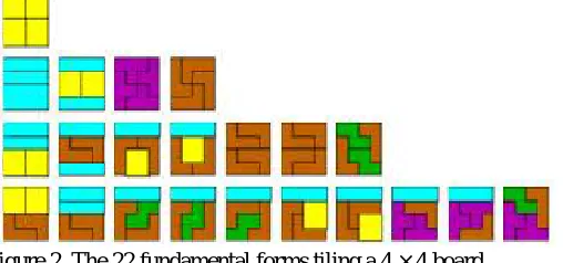
Figure 2. The 22 fundamental forms tiling a 4 × 4 board
Regarding additionally rotations and reflections there are 117 solutions.
As represented in Figure 2, we have 22 fundamental solutions in the 4 ×4 board (disregarding rotations and reflections).
One solution (first line) is unaltered by rotations and reflections, four solutions (second line) give a second version
applying the isometries. Seven forms can occur in four orientations (third line), and ten asymmetric cases in eight directions (last line).
C. Idea of Tetrolets
Vol. 4, Issue 4, April 2016
In the Haar filter bank, the low-pass filter and the high-pass filters are just given by the averaging sum and the
averaging differences of each four pixel values which are arranged in a 2 × 2 square. More precisely, with Ii,j =
{(2i,2j),(2i + 1,2j),(2i,2j + 1),(2i + 1,2j + 1)} for i,j = 0,1,..., N/2 − 1, we have a dyadic partition E = {I0,0,...,IN/ 2 −1,N /2 −1 } of the image index set I. Let L be the bijective mapping mentioned above which maps the four pixel pairs of Ii,jto the
set {0,1,2,3}, i.e., it brings the pixels into a unique order. Then we can determine the low-pass part
a = (a [i, j]), witha [i, j] =∑( , )∈ , ∈[0, L(i , j )]a[i ,j′] eq. (1) As well as the three high-pass parts for l = 1,2,3
= ( [i, j]), with [i, j] =∑( , )∈ , ∈[ , L(i , j )]a[i ,j′] eq. (2) Where the coefficients ∈[l,m],l,m = 0,...,3, are entries from the Haar wavelet transform matrix
= (∈[ , ]), =
1 1 1 1
1 1
−1 −1
1 −1 1 −1
1 −1
−1 1
eq. (3)
Obviously, the fixed blocking by the dyadic squares Ii,jis very inefficient because the local structures of an
image are disregarded. Our idea is to allow more general partitions such that the local image geometry is taken into account. Namely, we use tetromino partitions.
III.TETROLETFILTERBANKALGORITHM
We start with the input image, Then we will be able to apply J − 1 levels of the tetrolet transform. In the rth-level, r = 1, . . . , J − 1, we do the following computations.
Step1: Divide the low-pass image ar−1 into blocks Qi,jof size 4 × 4, i, j = 0, . . . , N/4r− 1.
Step2: In each block Qi,j we consider the 117 admissible tetromino coverings c = 1, . . . , 117. For each tiling c we apply
a Haar wavelet transform to the four tetromino subsets Is(c), s = 0, 1, 2, 3.
In this way we obtain for each tiling c four low-pass coefficients and 12 tetrolet coefficients. More precisely, in Qi,j we compute analogously to eq. (1) and eq. (2) the pixel averages for every admissible tetromino configuration c = 1, . . . , 117 by
,( )= ,( )[ ] ℎ ,( )[ ] =∑ ∈[0, ( , )]
( , )∈( ) [ , ], eq. (4)
As well as the three high-pass parts for l = 1, 2, 3 ,( )
= ,( )[ ] ℎ ,( )[ ] =∑( , )∈( )∈[ , ( , )] [ , ] eq.(5)
where the coefficients ∈[l,L(m, n)] are given in eq. (3) and where L is the bijective mapping mentioned in above relating the four index pairs (m, n) of Is(c) with the values 0, 1, 2, and 3 in descending order. That means, by the
one-dimensional indexing J(m, n) the smallest index is identified with the value 0, while the largest with 3. Then we choose the covering c∗such that the l1-norm of the 12 tetrolet coefficients becomes minimal C∗= gmin∑ ,( )1 = gmin∑ ∑ | ,( )
[ ]|. eq. (6)
Hence, for every block Qi,j we get an optimal tetrolet decomposition[ar,(c∗),w1r,(c∗) ,w2r,(c∗) ,w3r,(c∗) ]. By doing this, the
local structure of the image block is adapted. The best covering c∗ is a covering whose tetrominoes do not intersect an important structure like an edge in the image ar−1. Because the tetrolet coefficients become as minimal as possible a sparse image representation will be obtained. For each block Qi,jwe have to store the covering c∗ that has been chosen,
since this information is necessary for reconstruction. If the optimal covering is not unique, then we take the tiling c∗
that has already been chosen most frequently in the previous blocks. Thus, the coding of the used coverings becomes cheaper.
Step3:In order to be able to apply further levels of the tetrolet decomposition algorithm, we rearrange the entries of the vectors ar,(c∗)
and wlr,(c∗) into 2×2 matrices using a reshape function R,
/ , = ,(
∗)
=
,( ∗)[0] ,( ∗)[1]
,( ∗)[2] ,( ∗)[3] eq. (7)
Step4: After finding a sparse representation in every block Qi,jfor i, j = 0, . . . , N/4r − 1,we store the low-pass
matrix = / ,
, and the high-pass matrices = / , , , l = 1, 2, 3, replacing the low-pass image a
r−1
bythe matrix .
After a suitable number of decomposition steps, we apply a shrinkage procedure to the tetrolet coefficients in order to get a sparse image representation
Step5: Apply step 1 to 4 to the low pass image up to suitable number of decomposition levels.
IV.COSTOFADAPTIVITY
We will address the costs of storing additional adaptivity information. It is well known that a vector of length N and with entropy E can be stored with N · E bits. Hence, the entropy describes the required bits per pixel (bpp) and is an appropriate measure for the quality of compression. In the following, we propose three methods of entropy reduction in order to reduce the adaptivity costs.
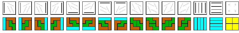
The simplest approach of entropy reduction is reduction of the symbol alphabet. The tetrolet transform uses the alphabet {1,. . . ,117} for the chosen covering in each image block. If we restrict ourselves to 16 essential configurations that feature different directions considerably reduce the entropy’s as well as computation time.
Figure 3. The a priori selected 16 tiling’s with different directions
A second approach to reduce the entropy is to change the distribution of the symbols. Relaxing the tetrolet transform we could ensure that only very few tiling’s are preferred. Hence, we allow the choice of an almost optimal covering ∗ in eq. (6) in order to get a tiling which is already frequently chosen. More precisely, we replace eq. (6) by the two steps:
1.
Find the set of almost optimal configurations that satisfy with a predetermined tolerance parameter .| ,( )[ ] ≤min | ,( )[ ] +
2. Among these tilings choose the covering c which is chosen most frequently in the previous image blocks. Using an appropriate relaxing parameter , we achieve a satisfactory balance between low entropy and minimal tetrolet
coefficients.
The third method also reduces the entropy by optimization of the tiling distribution. After an application of an edge detector we use the classical Haar wavelet transform inside flat image regions. In the image blocks that contain edges we make use of the strong adaptivity of the proposed tetrolet transform.
V. RESULTSANDANALYSIS
A. Standard Tetrolet Transform:
We apply a complete wavelet decomposition of an image and use wavelet shrinkage with global hard
thresholding choosing the threshold λ such that a certain number of largest wavelet coefficients is retained.
Vol. 4, Issue 4, April 2016
(a)
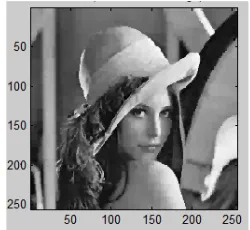
Input Image(b)
Tetrolet Transform PSNR=30.3034(c)
Biorthogonal 9-7 PSNR=28.1926 Figure 4.Reconstruction of ‘Lena’ image using Tetrolet and Biorthogonal Wavelet Transform.The 256 × 256 Lena image in Figure 4 shows that the tetrolet transformation gives excellent results. The reconstructed image achieves a remarkable PSNR of 30.3034 dB because the orientated edges are well adapted. Though the Haar-like tetrolets are not continuous, even for natural images the tetrolet filter bank outperforms the tensor product wavelets
with the biorthogonal 9-7 filter bank.
B. Modified Tetrolet Transform:
In order to reduce the storage costs we had discussed some approaches related to entropy reduction in section IV and those are the modified tetrolet transforms. Figure 5 shows the reconstruction of the lena image using the Modified Tetrolet Transforms.
(a) Tetrolet 16 PSNR=29.757
(b) Tetrolet relaxed PSNR=29.9938
(c) Tetrolet edge PSNR=30.1066 Figure 5. Reconstruction of the lena image using the Modified Tetrolet Transforms.
Tetrolet 16, Tetrolet relaxed, Tetrolet edge are three different methods that are used for adaptivity costs. All those 3 methods can be combinely applied on an input Lena image and results the following image (figure 6) which offers a low storage cost when compared to any other method.
Figure 6. Reconstruction of Lena Image using Tetrolet 16 Relaxed Edge method.
necessary. For a rough estimation of the complete storage costs of the compressed image with N2 pixels we apply a simplified scheme
= + +
Where = 16×M/N2 are the costs in bpp of storing M non-zero wavelet coefficients with 16 bits. The term gives the cost for coding the position of these M coefficients by − log − log . The third component appearing only with the tetrolet transform contains the cost of adaptivity, = E×R/N2, for R adaptivity values and the entropy E.
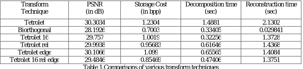
Comparison of Tetrolet transform, Biorthogonal wavelet transform and modified tetrolet transforms regarding quality (PSNR in dB), storage cost ( in bpp), decomposition time and reconstruction time is shown in Table 1.
Transform Technique PSNR (in dB) Storage Cost (in bpp) Decomposition time (sec) Reconstruction time (sec)
Tetrolet 30.3034 1.2304 1.4881 2.1302
Biorthogonal 28.1926 0.7003 0.33405 0.029841
Tetrolet 16 29.757 1.0019 0.32256 1.3728
Tetrolet rel 29.9938 0.95683 0.61646 1.4368
Tetrolet edge 30.1066 1.099 0.65565 1.4084
Tetrolet 16 rel edge 29.4846 0.85469 0.47406 1.3751
Table 1.Comparisons of various transform techniques
From above table, it is observed that the Tetrolets offer better PSNR results than any of the compared techniques by using lesser number of coefficients. It is also observed that the relaxed versions of the tetrolet result in lower Storage compared to the Tetrolet transform. The modified versions of the tetrolet transform offer better reconstruction time and deconstruction time than the tetrolet transform.
VI.CONCLUSIONANDFUTUREWORK
In this thesis we studied an adaptive image compression technique which has non- redundant tetromino basis functions and a fast filter bank algorithm. Implementation results prove that by selecting a suitable relaxing parameter, low cost of adaptivity using minimum Tetrolet coefficients can be achieved. It is also verified that Tetrolet Transform achieves similar reconstruction results as compared to tensor product wavelet transform using lesser number of coefficients. The modified versions of tetrolet transform also offers better results as compared to tetrolet transform. This compression technique can also be used for image denoising. The research could also be well extended to other image processing areas such as face recognition, edge detection and video editing.
REFERENCES
[1]. Jens Krommweh, “Tetrolet transform: A new adaptive Haar wavelet algorithm for sparse image representation,” Journal of Visual Communication and Image Representation, vol. 21, no. 4, pp. 364–374, May 2010.
[2]. D.L. Donoho, Wedgelets: nearly minimax estimation of edges, Ann. Statist. 27(3), (1999), 859–897.
[3]. H. Gu, “Image Compression Using the Haar Wavelet Transform”, Master’s thesis, East Tennessee State University, 2000. [4]. Wavelets and Subband Coding by Martin Vetterli&JelenaKovačević.
[5]. E.J. Cand`es and D.L. Donoho, New tight frames of curvelets and optimal representations of objects with piecewise C2 singularities, Comm. Pure Appl. Math. 57(2) (2004), 219–266.
[6]. Ram, I.; Elad, M.; Cohen, I., "Generalized Tree-Based Wavelet Transform," Signal Processing, IEEE Transactions on , vol.59, no.9, pp.4199,4209, Sept. 2011.
[7]. GerlindPlonka, “The Easy Path Wavelet Transform: A New Adaptive Wavelet Transform for Sparse Representation of Two-Dimensional Data,” Multiscale Modeling & Simulation, vol. 7, no. 3, pp. 1474–1496, Jan. 2009.
[8]. AvinashGhorpade, PriyankaKatkar, “Image Compression Using Haar Transform And Modified Fast Haar Wavelet Transform,” IJSTR volume 3, issue 7, July 2014.
[9]. C.S. Burrus, R.A. Gopinath, and H.Guo. Introduction to Wavelets and Wavelet Transfroms, Englewood Cliffs, NJ: Prentice Hall, 1998. [10]. M.N. Do and M. Vetterli, The contourlet transform: an efficient directional multiresolution image representation, IEEE Trans. Image
Process. 14(12) (2005), 2091-2106.
[11]. C.-L. Chang and B. Girod, Direction-adaptive discrete wavelet transform for image compression, IEEE Trans. Image Process. 16(5) (2007), 1289–1302.
Vol. 4, Issue 4, April 2016
[13]. V. Velisavljevi´c, B. Beferull-Lozano, M. Vetterli, and P.L. Dragotti, Directionlets: anisotropic multi-directional representation with separable filtering, IEEE Trans. Image Process. 17(7) (2006), 1916–1933.
[14]. Erwan Le Pennec and St´ephaneMallat, “Sparse geometric image representation with bandelets,” IEEE transactions on image processing, vol. 14, no. 4, pp. 423–438, 2005.