Influence of the turbulence representation at the inlet on the
downstream flow pattern in LES of backward-facing step
Jaroslav VOLAVY*, Matej FORMAN**, Miroslav JICHA***
Abstract: The impact of the choice of inlet boundary condition treatment on the fluid flow is studied in this work. The correct representation of the turbulence at the inlet to the domain is essential for the accuracy of Large Eddy Simulation. The inappro-priate specification of the inlet velocity has significant effect on the downstream flow pattern. The case of backward-facing step was used as a test case. Three different approaches of the inlet boundary conditions were studied: uniform velocity profile, mean velocity profile of the fully developed channel flow and velocity obtained from mapping velocity from plane positioned behind the inlet back to the inlet. The results of the simulations were compared with experimental results. It has shown, that using uniform velocity profile on inlet and even prescribing turbulent mean velocity profile without proper representation of turbulence fluctuations leads to unrealistic results.
1
INTRODUCTION
In the simulation of turbulent flow, the most important factor seems to be proper choice of turbulence model that will provide good representation of the flow. Another issue of great importance is specification of boundary conditions, especially inlet boundary condition. The velocity and another inflow data linked with turbulence prescribed by boundary condition should be consistent with chosen turbulent model. Description of mean velocity profile and other turbulence variables (turbulent kinetic energy, ...) obtained from analytical solution or from experiments can be regarded as sufficient for the RANS simulations. This approach was justified in [1]. It was shown that RANS model reach universal asymptotic behavior irrespective of the initial conditions. For Large Eddy Simulation, where the field on the inlet is turbulent, the situation is more problematic. Description of the flow is usually limited by knowledge of statistical quantities such as mean velocity profiles and mass fluxes. In LES, the data generated by inlet bound-ary condition should include an unsteady turbulent velocity signal representing turbulence at the inlet. Ideally, the simulation of upstream flow entering the computational domain will provide a good flow rep-resentation. However, unlimited extension in the upstream direction is not possible because of high computational cost. Therefore approximate inlet conditions must be specified.
A lot of methods were developed in the past. Kaltenbach et al. [2] used recycling method. Turbulent fluctuations are specified by running precursor simulation, whose only role is to provide main simulation with accurate boundary data. Another approach is to add synthetic turbulence at the inlet. Lund et al. [3] modified inlet velocity field by adding a random term to all velocity components. Klein et al. [4] proposed digital signal processing procedure to remedy lack of large- scale dominance in the inflow data generated by the random method.
* Jaroslav Volavy, Faculty of Mechanical Engineering, Brno University of Technology, Technická 2896/2, 616 69 Brno, Czech Republic, [email protected]
**Matej Forman, Faculty of Mechanical Engineering, Brno University of Technology, Technická 2896/2, 616 69 Brno, Czech Re-public, [email protected]
***Miroslav Jicha, Faculty of Mechanical Engineering, Brno University of Technology, Technická 2896/2, 616 69 Brno, Czech Republic, [email protected]
∂u¯i ∂t +
∂
∂xj(¯uiu¯j) =−
1
ρ ∂p¯
∂xi +ν ∂ u¯i ∂xk∂xk −
∂τij
∂xj. (1)
For evaluation of subgrid stress tensorτij is used Smagorinsky model:
τij−13δijτkk=−2νtS¯ij, νt= (CSΔ)2|S¯| (2)
¯
Sij= 12
∂u¯i ∂xj +
∂u¯j ∂xi
(3)
where|S¯|=|2 ¯SijS¯ij|1/2.
3
DESCRIPTION OF THE TEST CASE
For testing of different approaches to the inlet boundary condition was chosen backward-facing step flow. This case of flow is good benchmark for validating various models because it contains massive separation and consequent re-attachment. Separation bubble on the wall opposite to the step could appear for some geometrical and flow parameters.
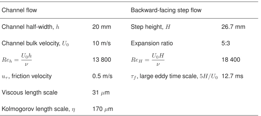
The geometry and flow properties was chosen according to the experimental study done by [6]. The Reynolds number of the inlet channel flow was 13 800, based on the bulk velocity of 10 m/s and the channel half-width of 20 mm. The expansion ratio was 5/3. The flow parameters of the inlet channel and backward facing step flow are in table 1.
Table 1:Flow parameters
Channel flow Backward-facing step flow
Channel half-width,h 20 mm Step height,H 26.7 mm
Channel bulk velocity,U0 10 m/s Expansion ratio 5:3
Reh= Uν0h 13 800 ReH =U0νH 18 400
uτ, friction velocity 0.5 m/s τf, large eddy time scale,5H/U0 12.7 ms
Viscous length scale 31μm
Kolmogorov length scale,η 170μm
Figure 1:The detail of the mesh near the trailing edge.
4
INLET BOUNDARY CONDITION
For the generation of the velocity on the inlet to the domain were used three different approaches. Let them denote as Case A, B and C. All cases have bulk velocity of 10 m/s.
Case A: Uniform velocity profile is prescribed at the inlet to the computational domain. No velocity fluctuations are present.
Case B: Mean velocity profile of fully turbulent channel flow is prescribed on the inlet. No velocity fluctuations are present.
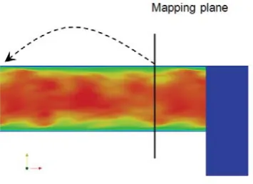
Case C:For the generation of the velocity on the inlet to the domain was used direct mapping approach [2]. The velocity on the inlet is obtained by direct mapping of the velocity from the plane with 3h(60 mm) offset from the inlet plane. The schematic picture of the mapping is shown in the Figure 2 (the placement of the mapping plane in this figure is only schematic). For the flow initialization was used following procedure: First was done simulation of inlet channel only using periodic boundary condition. For faster transition to the fully developed turbulent flow was used forcing scheme based on Ornstein-Uhlenbeck process proposed by [7]. When the fully turbulent regime was reached then the results of this pre-simulation was mapped to the inlet channel of the backward-facing step geometry.
Figure 2: Scheme of inlet data mapping.
5
RESULTS
no separation bubble on the top and the reattachment point is much further from the step.
Figure 3: Instateneous velocity for uniform in-let profile (Case A)
Figure 4: Instateneous velocity for fully turbu-lent flow at inlet (Case C)
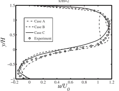
In the figure 5 are velocity profiles in short distance from the step. It could be noticed that the uniform inlet velocity gives nonrealistic results. From the flatness of the profile above the step could be stated that the length of the inlet channel is not long enough in order to develop turbulent velocity profile. Velocity profiles further from the step (x/H = 5) are in the figure 6 . Negative values of velocity at the top of the domain predicted in cases A and B indicates that separation bubble has been formed in this region. It is because of lack of wall-normal velocity fluctuation, which leads to absence of turbulent mixing mechanism and the main stream is bend down due the strong adverse pressure gradient. Case A also fails in prediction of re-attachment of the flow behind the step.
−0.2 0 0.2 0.4 0.6 0.8 1 1.2 −1
−0.5 0 0.5 1 1.5
y/H
u/U
0 x/H=2
Case A Case B Case C Experiment
Figure 5:Velocity profile at position x/H=2
−0.2 0 0.2 0.4 0.6 0.8 1 1.2 −1
−0.5 0 0.5 1 1.5
y/H
u/U
0 x/H=5
Case A Case B Case C Experiment
Figure 6: Velocity profile at position x/H=5
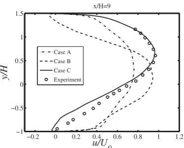
Figures 7 and 8 show situation far behind the step. Case B also fails in prediction of re-attachment. On the other side, case C predicts re-attachment point quite well. Re-attachment point predicted by case C is at position x/H = 9.2 (experiment predicts this point at position x/H=8.4).
6
CONCLUSIONS
−0.2 0 0.2 0.4 0.6 0.8 1 1.2 −1
−0.5 0 0.5 1 1.5
y/H
u/U
0 x/H=7
Case A Case B Case C Experiment
Figure 7:Velocity profile at position x/H=7
−0.2 0 0.2 0.4 0.6 0.8 1 1.2 −1
−0.5 0 0.5 1 1.5
y/H
u/U
0 x/H=9
Case A Case B Case C Experiment
Figure 8: Velocity profile at position x/H=9
simulation. The first two cases were not able to predict these fluctuations what resulted in the inclination of the incoming stream downwards and forming a separation bubble at the top of the domain. This is not in accordance with real experimental study. The inclination of the stream also affected the position of the re-attachment of the stream behind the step, the stream is re-attached too early.
The only proper way of representation of the inlet data presented in this work is running precursor simulation of the inlet channel using turbulence forcing and then mapping resulting fields to the main domain and direct mapping of velocity to the inlet. This is most complicated case but gives accurate results close to the experiment. The prediction of the re-attachment point could be improved by using more advanced subgrid model, for example some variant of localized Smagorinsky model [7].
ACKNOWLEDGMENT
The support of grants GA CR 101/08/0096 as well as the project FSI-S-11-6 is gratefully acknowledged.
REFERENCES
[1] George W.K., Davidson L.: Role of initial conditions in establishing asymptotic flow behavior, AIAA Journal, 42(3), 2004, 438446
[2] Kaltenbach H.J., Fatica M., Mittal R., Lund T.S., Moin P.: Study of flow in a planar asymmetric diffuser using large eddy simulation, Journal of Fluid Mechanics, 1999, 151185
[3] Lund T., Wu X., Squires D.: Generation of turbulent inflow data for spatially-developing boundary layer simulations, Journal of Computational Physics, 1998, 233258
[4] Klein K., Sadiki A., Janicka J.: A digital filter based generation of inflow data for spatially developing direct numerical or large-eddy simulations, Journal of Computational Physics, 186, 2003, 652665
[5] Ghosal S., Lund T., Moin P., Akselvoll K.: A dynamic localization model for large-eddy simulation of turbulent flows, J. Fluid Mech., 286, 1995, 229-255
[6] Fessler J.R., Eaton J.K.: Turbulence modification by particles in a backward-facing step flow, J. Fluid Mech., 394, 1999, 97-117