WIRELESS BASED PROGRAMMABLE ELECTRONIC
DELAY MODULE FOR DEFENCE APPLICATIONS
Akshya Bhujbal
1, Prajakta Gaikwad
2, C. P. Mahajan
3Kameshwar Mishra
4, A. Sudhir
51,2,3,4,5
Department of Electronics and Telecommunication,
Sinhgad Academy of Engineering, Savitribai Phule Pune University, (India)
ABSTRACT
Accuracy is what today’s world is all about. The life of a soldier and the outcome of the war is purely dependent
on the accuracy of the weapons. Protecting soldiers from the enemies on the battlefield is as important as
defeating them. Weapon failures during a war can cause catastrophic consequences.
The solution to these consequences is the Wireless Based Programmable Electronic Delay Module. It controls
the outcome of a smoke grenade when launched from a tank. Smoke grenades can be thrown prior to
movements,such as flanking manoeuvres or retreatin order to provide a wall of visual distraction that reduces
the accuracy of enemy fire and temporarily deceives them. If a mechanical failure occurs during the launch it is
important that the outcome still turns out to be in our favour and no injuries are caused.
Our project incorporates Wireless Based Programmable Electronic Delay in the smoke grenade in order to
resolve mechanicalfailures.
Keywords: ADC, Mechanical Failure,PIC16F877A, Smoke Grenade, Smoke Discharger
I. INTRODUCTION
reasons and hence directly implemented the voltage that it will create from the acceleration using a potentiometer.
II. PROBLEM
Mechanical errors cannot be avoided in battlefields but their outcome can be controlled very carefully to ensure that it works according to the protocol. A mechanism inside the smoke discharger holds the grenade in place, it provides the required thrust for the grenade to launch. This mechanism may act faulty due to various reasons causing variation in the launch (thrust) of grenade. To launch a grenade, explosives are lit. If the tool for launch considerably metal clips are too tight or lose, it may cause the grenade to fall near our own tank or far from target location which will put our own tank in danger.
Now there are three cases according to the mechanical errors:
The thrust formed is too low and hence is predicted that the smoke grenade may fall near our own tank.
This will not provide enough smoke screen and our tank will be exposed. Also the soldiers may get hurt in the explosion.
The thrust is ideal and smoke grenadewill detonate at desired range.
The thrust is more and hence predicted that the grenade will fall way out of desired range.
Also, many times there are live grenades lying on the ground after the war is over. This can be dangerous to the citizens living in that area. Such grenades should be retrieved from the war field but searching for grenades in such big area is a tedious task and exhausting for the soldiers. There should a simpler way to retrieve such live grenades.
III. METHODOLOGY AND IMPLEMENTATION
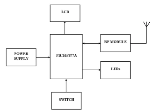
The system can be divided into 2 sub-systems: A) Transmitter
B) Receiver
When the potentiometer value is given from the receiver, the value is sent to the transmitter using the RF module. The microcontroller then takes the decision using the ADC values and decides the case. That information is sent to the receiver using RF module. The switch does nothing but launch the circuit. The circuit has an LCD display that displays the pot value, the latitude, longitude and the time of detonation received from the receiver.
Two LEDs, a green and red are used. Red indicates detonation and green indicates fin movement.
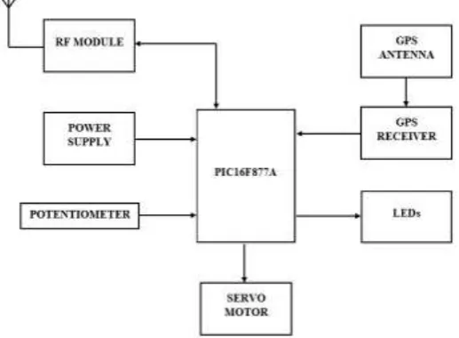
Fig 2. Block Diagram of the Receiver (Grenade circuitry)
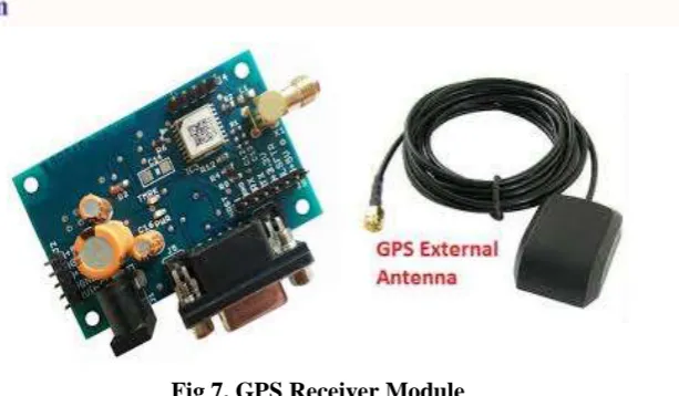
Potentiometer takes value and the value is sent to the transmitter. The case is decided by the microcontroller and the LEDs are lighted according to that. If the case requires, fin movement is enabled using servomotor. Just before detonation, GPS location of grenade is sent to the microcontroller of the transmitter which in turn displays it. The GPS module is connected to a GPS antenna.
On literature survey it was found that in paper [2], ZIGBEE is a new short distance, low data rate wireless network technology. It is built on the IEEE 802.15.4 low rate wireless Personal Area Network standard. PIC16F877A controller is used in a predominant way because it is rich in peripherals and hence many devices can be interfaced at ease, it is also very cheap and can be easily assembled and programmed. The PIC microcontroller controls the devices and sends the sensor values to the PC via ZIGBEE module. In paper [1] it was found that the analog to digital convertor acquisition time selection for the analog to digital convertor specified accuracy. The analog to digital convertor 10 bit result is in analog to digital convertor result register (ADRESH: ADRESL) which is configured for right justification.
3.1Development of hardware:
3.1.1 PIC 16F877A Microcontroller:
PIC is a family of modified Harvard architecture microcontrollers. The acronym PIC
memory, self-programming, an ICD, 2 Comparators, 8 channels of 10-bit Analog-to-Digital (A/D) converter, 2 capture/compare/PWM functions, the synchronous serial port can be configured as either 3-wire Serial Peripheral Interface (SPI™) or the 2-wire Inter-Integrated Circuit (I²C™) bus and a Universal Asynchronous Receiver Transmitter (USART). All of these features make it ideal for more advanced level A/D applications in automotive, industrial, appliances and consumer applications. PIC 16F877A is a size compatible microcontroller that will reduce cost of making and provide just the efficiency needed for this project. [4].Even though this project has a future scope of using any higher end microcontroller too, PIC 16F877A provides the right amount of features to make this project work efficiently.
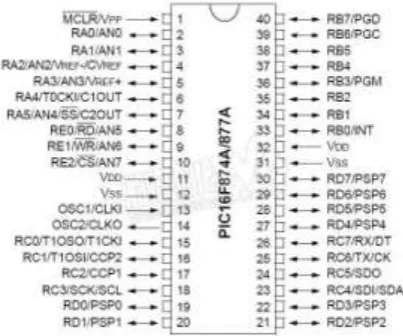
Fig 3. Pin Diagram of PIC16F877A
3.1.2 Voltage Regulator:
Apower supply of 5 volts is required. This can be obtained by using avoltageregulator. A LM7805 Voltage Regulator is a voltage regulator that outputs +5 volts. A LM7805ends with "05", thus, its output is 5 volts. The "78" part is just the convention that the chipmakers use to denote the series of regulators that output positive voltage.Voltage regulator can accept an input voltage of 36 volts, it is recommended to limit thevoltage to 2-3 volts higher than the output regulated voltage. For a 5-volt regulator, not more than 8 volts should be applied as the input voltage. The difference between the inputand output voltage appears as heat. The LM7805 is a three-pin IC.
3.1.3 Bridge Rectifier:
A bridge rectifier is an arrangement of four or more diodes in a bridge circuitconfiguration which provides the same output polarity for either input polarity. It is usedfor converting an alternating current (AC) input into a direct current (DC) output.
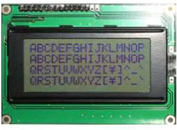
3.1.4 LCD:
We have used 16x4 LCD display module. It means there are 4 lines and each line will display 16 characters.The LCD will display the Pot voltage on line 1, Latitude on line 2, Longitude on line 3 and Time on Line 4. An LCD is used in this project for the sole reason that a person operating from the tank must be aware of the situations at all times. An LCD will display not only the GPS co-ordinates, but also the voltage due to g-sensor/accelerometer. This will help the soldier to be aware of the outcome of the grenade before detonation. LCD is being used in the 4-bit mode [3].
Fig 5. LCD Display module
3.1.5RF module (Zigbee):
The XBee Series 2 OEM RF Modules were engineered to operate within the ZigBee protocol and support the unique needs of low-cost, low-power wireless sensor networks.
The modules require minimal power and provide reliable delivery of data between remote devices. The use of Zigbee for this project will prove the most beneficial as its reliable communication will allow correct decision making. Its range will allow rigid and accurate communication. Its size will ensure that it fits well into the grenade without being an issue. [5]
Fig 6.ZigBee Module
3.1.6GPS Module
Fig 7. GPS Receiver Module
3.1.7Servo Motor
A servo motor is used to move the fin of the grenade at a pre-decided angle which will help in making the path of the grenade shorter in case of getting unnecessarily more thrust. It can be used for its angle accuracy and easy use.
Fig 8.Servo Motor
3.2 Development of software
For proper decision making of the grenade, a firmware was developed in MPLAB X IDE. MPLAB X IDE is a software program that runs on a PC (Windows®, Mac OS®, Linux®) to develop applications for Microchip microcontrollers and digital signal controllers. It is called an Integrated Development Environment (IDE), because it provides a single integrated "environment" to develop code for embedded microcontrollers. The paper [6] presents the design of low cost greenhouse monitoring system to monitor a greenhouse temperature and humidity parameters by applying the ZigBee technology as the WSN system. During the design process, Peripheral Interface Controller (PIC), LCD Display and Zigbee as the main hardware components is used as hardware components while C compiler and MP Lab IDE were used for software elements.
IV. RESULT
This paper has been written to enable accuracy in the working of smoke grenade and Wireless Programmable Electronic Delay Module does just that. Though mechanical errors cannot be corrected, its outcome is controlled in way that ensures ideal working. The voltage is read by the microcontroller and appropriate action is taken in the way of cases. The result can be seen by the LED that is on. Red LED indicates detonation and green LED indicates fin movement. The results for all the cases are:
a) Voltage range indicating low thrust will initiate no detonation mode where the grenade will not detonate. LED indicating detonation will not turn on.
b) Voltage range indicating ideal thrust will initiate detonation at ideal time. Red LED is turned on indicating detonation.
c) Voltage range indicating more thrust will initiate fin movement to drop the grenade before the full path is completed and variable detonation delays are given according to voltage value. Green LED will blink indicating fin movement and red LED will blink programmed seconds later indicating detonation of grenade.
Each time, the GPS module sends the location of the grenade just before detonation. When no detonation takes place, it sends the location co-ordinates at a pre-decided time. This location can be used to collect these live undetonated grenades later.
V. CONCLUSION
This project will work well in a battlefield scenario. It will help control the smoke grenade remotely and at a safe distance. The project is feasible for the army to be implemented. Since we are using a GPS module, we can ensure that no undetonated grenade goes unnoticed. It can be handled by any soldier without any extensive training which makes it very handy. All the decisions will be made by the grenade itself making it reliable considering the amount of time at the soldiers’ hands. This project has a lot of future scope due to adaptability and flexibility.
REFERENCES
[1] “Datasheet of PIC 16F877A microcontroller”, www.microchip.com.
[2] P.V. Mane-Deshmukh, B.P. Ladgaonkar, S. C. Pathan, S. S. Shaikh,“Microcontroller Pic 18f4550 Based
Wireless Sensor Node to Monitor Industrial Environmental Parameters”International Journal of Advanced
Research in Computer Science and Software Engineering Research Paper Volume 3, Issue 10, October 2013 ISSN: 2277 128X.
[3] “Datasheet of LCD”
[4] M Shanmugasundaram1 , G Muthuselvi2 , S Sundar, “Implementation of PIC16F877A Based Intelligent
Smart Home International” Journal of Engineering and Technology Research report ESAII RR-06-12 July
27, 2006.
[6] Salleh, Azahari and Abd Aziz, MohamadZoinolAbidin and Misran, Mohamad Harris and Mohamad, NajmiahRadiah (2013), “Development of Greenhouse Monitoring using Wireless Sensor Network through
ZigBee Technology”. International Journal of Engineering Science Invention (IJESI), 2 (7). pp. 6-12. ISSN
2319 – 6734.
[7] “Datasheet of GPS module”
[8] Abdel IlahNourAlshbatat “Automated Mobility and Orientation System for Blind or Partially Sighted
People”, Department of Electrical Engineering Tafila Technical University, Tafila 66110,