DIFFERENT CODES USED FOR REDUCING
THERMAL HYDRAULICS PROBLEMS IN NUCLEAR
REACTORS: A REVIEW
Deepak Sharma
1, Krishna Murari Pandey
21,2
Department of Mechanical Engineering, NIT Silchar, Assam, (India)
ABSTRACT
The energy released in nuclear fission appears as kinetic energy of fission reaction products and finally as heat
generated in the nuclear fuel elements. This heat must be removed from the fuel and reactor core and used to
produce electrical power. The primary goals of thermal core design include achieving a high power density (to
minimize core size), a high specific power (to minimize fuel inventory) and high coolant exit temperatures (to
maximize thermodynamic efficiency). On the one hand, higher coolant flow rates will lead to better heat transfer
coefficients and higher CHF limits. On the other hand, higher flow rates will also result in larger pressure
drops across the core, hence larger required pumping powers and larger dynamic loads on the core
components. Thus, the role of the hydrodynamic and thermal-hydraulic core analysis is to find proper working
conditions that assure both safe and economical operation of the nuclear power plant. In the last four decades,
large efforts have been undertaken to provide reliable thermal-hydraulic system codes for the analyses of
transients and accidents in nuclear power plants. Whereas the first system codes, developed at the beginning of
the 1970s, utilized the homogenous equilibrium model with three balance equations to describe the two-phase
flow, nowadays the more advanced system codes are based on the so-called “two-fluid model” with separation
of the water and vapor phases, resulting in systems with at least six balance equations. The wide experimental
campaign, constituted by the integral and separate effect tests, conducted under the umbrella of the
OECD/CSNI was at the basis of the development and validation of the thermal-hydraulic system codes by which
they have reached the present high degree of maturity. However, notwithstanding the huge amounts of financial
and human resources invested, the results predicted by the code are still affected by errors whose origins can be
attributed to several reasons as model deficiencies, approximations in the numerical solution, nodalization
effects, and imperfect knowledge of boundary and initial conditions.
Keywords: Thermal Hydraulics Codes, CFD, Coolant, Heat Transfer, Nuclear Reactor.
I. INTRODUCTION
In a power reactor, the energy produced in fission reaction manifests itself as heat to be removed by a coolant
and utilized in a thermodynamic energy conversion cycle to produce electricity. Although this process is
essentially the same as in any other steam plant configuration, the power density in a nuclear reactor core is
typically four orders of magnitude higher than a fossil fueled plant and therefore it poses significant heat transfer
heat transport system rather than nuclear considerations. Various factors that influence the power level include
the coolant type, core configuration to maximize heat transfer surface area, coolant flow rate, thermo-physical
properties of coolant and core materials, and consideration of material compatibilities. Thermal-hydraulics has
played a vital role since the 1950s in the design, operation, performance and safety of nuclear power plants. As
our knowledge in thermal-hydraulics progressed because of intense research and development (R&D)
throughout the world, the design, operation and performance of nuclear power reactors have improved
significantly. Authoritative reviews of role and challenges of thermal hydraulics for operating and advanced
reactors have been conducted in the past. A review is also made of the computer codes developed for
thermal-hydraulic analysis of nuclear reactors. The intention of this review is to compare these codes on the basis of
their numerical method and physical models with particular attention to the two-phase flow and heat transfer
characteristics.The thermal hydraulic analysis of nuclear reactors is largely performed by what are known as
“System Codes”. These codes predict the flows in the complex network of pipes, pumps and vessels that
together form the thermal hydraulic systems of a nuclear reactor. Codes in this category include the US codes
RELAP, TRAC and TRACE and the European codes CATHARE and ASTEC. Best-estimate thermal-hydraulic
codes (e.g., RELAP, TRAC, CATHARE and ATHLET) are, in general, based on equations for two-phase flow
which are typically resolved in Eulerian coordinates.Numerous computer codes have been written to calculate
the thermal-hydraulic characteristics of the reactor core and the primary loop under steady-state and operational
transient conditions as well as hypothetical accidents. New versions of some of these codes are still to come.
The main purposes of the continuing effort in the development of such computer codes have been improved
computational effectiveness and improved ability to predict the response of the core and the primary loop.
Therefore, efforts have been continued to incorporate the recent models and methods of analysis in the areas of
both hydrodynamics and heat transfer in two-phase flow to the extent that their prediction are reasonably
reliable.
II. LIST OF REVIEWED THERMAL HYDRAULIC CODES
Name of Code Reference Number Name of Code Reference Number
COBRA-I 1 RELAP5 12
COBRA- I I 2 WOSUB 13
COBRA-III 3 RETRAN 14
COBRA-IIIC 4 TRAC 15
COBRA-IIIP 5 THERMIT 16
COBRA-IV-I 6 CATHARE 17
COBRA-DF 7 ATHLET 18
COBRA-TF 8 RELAP4-MOD6 19
RELAP2 9 RELAP4-MOD7 20
RELAP3 10 RELAP 4-EM 21
However, such codes are fundamentally limited in that they are at heart only one-dimensional. If a part of the
plant can reasonably modeled as one-dimensional flow in a pipe, these codes are excellent. However, there are
plainly many important phenomena and locations where this one- dimensionality is not a good approximation.
An obvious example of this might be flow within the bulky, 3-dimensional reactor vessel itself. There have been
attempts to extend these System Codes to handle multi-dimensional effects. These have had some success, but
there is naturally a trade-off between the fidelity of the representation and the computational complexity. It is
over-simplified, but one might characterize a "3D System Code" as an array of one dimensional parallel pipes,
allowed to interact „sideways‟ with each other via some „cross flow‟ coupling. The models so produced can be
better than the original one-dimensional ones, but do not represent complex flows well.The most capable tool
available to us for modeling these multi-dimensional effects is computational fluid dynamics (CFD). Modern
CFD is able to produce high-quality predictions flows in complex geometries, but only with the use of large
computing resources. It would be utterly impractical to build a CFD model of, for example, the entire primary
circuit of a PWR.The most widely used of these codes, and the worldwide workhorse of nuclear reactor thermal
analysis, is the RELAP suite, originating with the US NRC.Best-estimate system codes are currently used for
the following:
(i) safety analysis of accident scenarios;
(ii) quantification of the conservative analyses margin;
(iii) licensing purposes if the code is used together with a methodology to evaluate uncertainties;
probabilistic safety analysis (PSA);
(iv) development and verification of accident management procedures;
(v) reactors design;
(vi) analysis of operational events;
(vii) core management investigation.
In the comparison that follows, both the advantages and drawbacks are noted in each code and ultimately it is
attempted to assess the capability of each code for handling a specified case.
III. CLASSIFICATION OF NUCLEAR REACTOR THERMAL HYDRAULICS CODES
The existing thermal hydraulic codes may be classified under several categories as follows:
a)
Capability of the system analysis
This contains two different classes of codes, namely, system component codes and loop codes. Basically, the hot
channel or the fuel behavior codes are system component codes; however, some of these codes are extended to
other situations far removed from subchannel (one channel) geometry. Integration of the down comer, jet pumps
(in BWR's), bottom flooding, UHI and the like models into a component codes, makes itta vessel code. As
distinct from the loop codes which are devised to analyze the whole primary side including reactor core and the
secondary side, a variety of codes ranging from hot channel to vessel codes are called system component codes
b) Type of Two-Phase Flow Modeling
This part deals with the mathematical models used in thermal hydraulic codes to calculate the characteristics of
the two-phase flow either in the reactor core or in the primary loop. The two pertinent methods in this respect,
namely, the homogeneous equilibrium model and the two-fluid model fall in this category.
c) Range of Application
Since the capability of each code to handle flow and fuel rod calculations depends upon the mathematical
models used to represent the physical situations as well as the numerical methods employed, codes can be
classified in these respects into steady-state, transient and accident analysis (such as LOCA) codes. Naturally,
the more demanding codes in this respect are ATWS and LOCA codes.
d) Type of Application
Codes may also be classified based upon their types, i.e., Best Estimate (BE) type and Evaluation Model (EM)
type. The latter group are basically devised for the purpose of licensing. The type of nuclear reactor for which
thermal hydraulic codes are devised (such as PWR, BWR and LMFBR) may be another category.
IV. CLASSIFICATIONS ACCORDING TO SYSTEM ANALYSIS CAPABILITY
4.1 Component Codes
A core thermal hydraulic assessment necessitates analysisof fluid passing axially along the parallel rod arrays.
Suchanalysis is difficult to conduct due to the degree of freedomassociated with parallel rod array and the
two-phase flow andheat transfer involved in nuclear reactors. In addition, a radial and axial variation of the fuel rod
power generation exacerbates this situation.Assumptions have been made to simplify the task of modelingthe
hydrodynamics and heat transfer characteristics ofthe rod arrays.Generally, there are three pertinent
methodsused inrod bundle thermal hydraulic analysis of the nuclear reactorcore as well as heat exchangers,
namely, (a)-subchannel analysis,(b)-porosity and distributed resistance approach and finally(c)-benchmark
rod-bundle analysis which uses a boundary fittedcoordinate system.The first approach is widely used in the
subchannel codessuch as COBRA, FLICA, HAMBO and THINC. Whereas the secondapproach is employed in
THERMIT.The subchannel approach will be more elaborated upon here,while a discussion in detail of these
three concepts is presentedin Ref 21.In the subchannel approach, the rod array is consideredto be subdivided
into a number of parallel interacting flow sub channels between the rods. The fluid enthalpy and mass velocityis
then found by solving the field or conservation equationsfor the control volume taken around the
subchannel.Although a rod-centered system with subchannel boundaries defined by lines of "zero-shear stress"
between rods (Fig. l) seems to be well-defined control volumes, it has become customary to consider a coolant
Fig 1 Coolant Centered Subchannel
4.2 Thermal Hydraulics Codes for Light Water Reactors
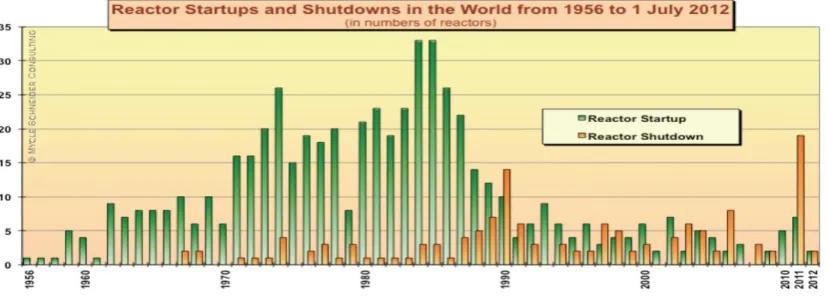
Around 350 Light Water Reactors (BWR and PWR) are operating throughout the world(NN, 2011). Apart from
improvement in their capacity factors, many BWRs and PWRs have been uprated from their Original Licensed
Thermal Power (OLTP). This has been achieved by combination of plant and fuel modifications, and by
application of best-estimate (BE) Modeling and Simulation (M&S) capabilities that have enabled the recovery
of conservatism in safety analysis. Reactor startup and shut down in the world as shown in Fig. 2.
Fig 2 Reactor Startups and Shutdowns in the World
Other BWR and PWR fuel vendors have followed similar approaches with codes such as SRELAP and
WCOBRA/TRAC (Leberig et al., 2009; Curca-Tivig, 2009; Yano et al., 2010; Westinghouse, 2007). The
analytical methods used in the original design and licensing of the early BWRs were relatively simple; typically
a four equation drift flux model was used for the thermal hydraulics, and point kinetics was used for transient
nuclear kinetics. The calculations were done in sequential steps; one code would calculate the system response
for the reactor primary system, one code would be used for the limiting fuel bundle to determine the thermal
margins, and a separate code would be used for containment analysis if needed. Loss of Coolant Accident
(LOCA) analysis is a typical example on such sequential analyses. Significant conservatisms were included in
the analyses; conservatisms were typically included to bind the uncertainties in the analytical models and
correlations. Most plants were therefore LOCA limited. At the same time the development of more advanced
methods, as example based on the TRAC-BWR code (Borkowski et al., 1992) was initiated. These advanced
interfacial and wall shear and heat transfer. The two-fluid model includes both a 1D and a multi-dimensional
formulation. In addition models for non-condensable gasses and dissolved boron in the liquid phase were included. A 3D nuclear kinetics model consistent with GE‟s 3D core simulator PANAC and an improved fuel
thermal-mechanical model were included. The applications abandoned the use of conservative models and
switched to the best-estimate models coupled with a statistical quantification of total uncertainties from models,
initial conditions and plant parameter uncertainties. The application process followed the Code Scaling
Applicability and Uncertainty (CSAU) methodology (USNRC, 1989a) and USNRC RG 1.157 (USNRC,
1989b). TRACG, the GE proprietary version of TRAC-BWR code, was approved by USNRC for the reactor
stability „Detect and Suppress‟ solutions in 1996 (BWROG, 1996) and for operating transients in 2001 (Andersen et al., 2006b). The stability Detect and Suppress Solution – Confirmation Density (DSS-CD) for
Maximum Extended Load Line Limit Analysis Plus (MELLLA+) operation was approved in 2007 (GEH, 2007).
In addition, TRACG has been used and approved by USNRC for transient, LOCA, stability and Anticipated
Transients without Scram (ATWS) applications for the ESBWR (GEH, 2010a,b,c,d). The introduction of better
models combined with the more rigorous statistical method used to quantify the uncertainty generated even
further margin improvement for the BWR.
4.3 Thermal Hydraulic Codes for AHWR
The Indian advanced heavy water reactor (AHWR) is a 920 MW vertical pressure tube type boiling light water
cooled and heavy water moderated system (Sinha and Kakodkar, 2006). Analysis has been carried out for
simulating loss-of-coolant accident (LOCA) at inlet header in a natural circulation type reactor developed as the
advanced heavy water reactor (AHWR). In this research it covers a case of LOCA due to 200% break at inlet
header which is double ended rupture. The maximum clad surface temperature has been predicted in different
cases by using the thermal hydraulic safety code RELAP5/Mod4.0. This reactor is equipped with emergency
core cooling system (ECCS) and isolation condensers (ICs) to remove decay heat during LOCA. This ECCS
provides cooling to fuel in passive mode during first fifteen minutes of LOCA and it is achieved by high
pressure injection from advanced accumulator. Thermal hydraulics parameter analyze by using the advance
RELAP5/MOD 4 simulation code which incorporated these advance models mentioned in below. The effect of
these models are-
Exact simulation of water road.
Conditions in ECCS header.
CCFL (Countercurrent Flow Limitations) model in the reactor core.
Momentum mixing & heat structure model in ECCS header.
Reactor kinetics (neutronics) modeling.
Postulated scenarios during Station Blackout are analyzed and mention in Tyagi et al. (2010b).This Study shows
that the max clad temperature in hot pin and hot channel is within acceptable limit as per ECCS acceptance
criteria during 200% large break LOCA. Results obtained by thermal hydraulic analysis of proposed natural
circulation reactor are found to be within acceptable limits as mentioned above. Conclusion is based on
deterministic assessment. Number of scenarios in different categories having been analyzed in design basis and
analyzed at different location. 200% inlet header break is found to be enveloping initiating event in design basis
category considering events in other categories also. Detailed ECCS acceptance criteria are shown in Fig 3.
Maximum fuel rod clad temperature shall not exceed 1477 K.
Fig 3 Hot Pin Clad Surface Temperature Transient at Maximum Axial Location for Hot
Channel 05 Volume
4.4 Thermal-Hydraulic Code for Lead-Cooled Nuclear Fast Reactors
A new multi-physics simulation tool FRENETIC (Fast Reactor Neutronics/Thermal-hydraulics) is presented for
the quasi-3D analysis of a lead-cooled fast reactor core with the hexagonal fuel element configuration, as
currently proposed within the framework of the European project LEADER. The tool implements coupled
neutronics (NE) and thermal-hydraulic (TH) models. In the NE module, a 2D + 1D full-core multi-group
diffusion solver has been developed based on a coarse mesh nodal scheme and adapted to cope with the
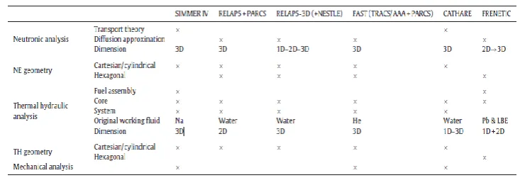
hexagonal geometry. In Fig. 4 we also distinguish between codes (as FRENETIC) applicable to the full core, or
to the whole reactor (i.e., including also the external circuit(s) feeding the core
Fig 4 Representation of Available Tools for Thermal-Hydraulic Modeling
Table 1 Main Features of the FRENETIC Code Compared to the Already Available Tools for
The performance of FRENETIC has been tested in a few selected test cases reported here. The successful
validation of the TH model in the case of a single hexagon, against experimental data from the ICE test section
at the ENEA Brasimone research center, has already been presented elsewhere (Zanino et al., 2012; Bonifetto et
al., 2012b). The fuel is assumed to be UO2 (Popov et al., 2000), while the wrapper material is 18/12 stainless
steel (similar to AISI 316). The number of hexagons (fuel elements) in the fuel region of the reference
configuration is 451, unless otherwise noted, the reactor thermal power is 1500 MW and the axial power form
factor ϕ = 1.3 (Sobolev et al., 2007). The other main geometrical parameters, taken from (Sobolev et al., 2007;
Mansani, 2012). The new code FRENETIC has been presented for the coupled neutronics/thermal-hydraulic
analysis of lead-cooled fast nuclear reactors, as currently foreseen in the European program within the
Generation IV framework. Both the neutronics and thermal-hydraulic modules of FRENETIChave been
benchmarked against analytical solutions. The extension of the neutronics model to include 3D and transient
capabilities is under way. In a separate, parallel effort, the multi-hexagon thermal-hydraulic model will be
validated against experimental data. Eventually, the coupled neutronics/thermal-hydraulic model should also be
validated against experimental data.
4.5 Thermal-Hydraulics Code for High Temperature Gas Cooled Reactor
DYN3D is a nodal diffusion code for 3D steady-state and transient analysis of Light Water Reactor (LWR)
cores with hexagonal or square fuel element geometry. In addition to the neutron kinetics, it comprises of a
thermal-hydraulics model for flow in parallel coolant channels.The possibilities of new computer generations
allow a much more detailed analysis of complex physical and chemical interrelations which play a role in the
determination of the plant behavior in normal operation and under accident conditions. Therefore, by using
existing calculation methods for High Temperature Gas Cooled Reactors (HTGRs) and Light Water Reactors
(LWRs), a new generation of simulation tools can be developed for HTGRs with pebble-shaped and prismatic
fuel assemblies and for related systems for process heat and hydrogen generation. The RPT methodology allows
combining the high spatial resolution of MC codes with the superior computational speed of deterministic lattice
codes. Computational efficiency is essential, since forfew-group cross section sets generation about hundreds to
thousands branch-off calculations are required. At the first stage, a MC code is used to simulate an HTGR fuel
element with explicitly described TRISO particles at the beginning of life (BOL) and at the nominal operational
conditions.
A simplified version of the prismatic HTGR core developed by Idaho National Laboratory (INEEL) in the frame
of Next Generation Nuclear Plant (NGNP) (MacDonald et al., 2003) project was considered as a reference core
in this comparison. The NGNP core includes control rods channels asymmetrically distributed in the fuel blocks
and the outer reflector. However, these control rods channels were not modeled in this study. The modified
HTGR core layout is shown in Fig. 5. Materials specifications, TRISO particle layers dimensions, and packing
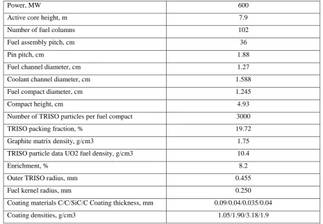
fraction of TRISO particles were adopted from (DeHart and Ulses, 2009). The major core parameters are
Fig. 5 Simplified HTGR Core Model
Table 2: The Simplified HTGR Core Data
Power, MW 600
Active core height, m 7.9
Number of fuel columns 102
Fuel assembly pitch, cm 36
Pin pitch, cm 1.88
Fuel channel diameter, cm 1.27
Coolant channel diameter, cm 1.588
Fuel compact diameter, cm 1.245
Compact height, cm 4.93
Number of TRISO particles per fuel compact 3000
TRISO packing fraction, % 19.72
Graphite matrix density, g/cm3 1.75
TRISO particle data UO2 fuel density, g/cm3 10.4
Enrichment, % 8.2
Outer TRISO radius, mm 0.455
Fuel kernel radius, mm 0.250
Coating materials C/C/SiC/C Coating thickness, mm 0.09/0.04/0.035/0.04
Coating densities, g/cm3 1.05/1.90/3.18/1.9
A preliminary procedure for analysis of HTGR core using HELIOS and DYN3D codes was established and
tested. Good agreement in keff and radial power distribution between DYN3D and reference MCNP results was
observed. Nevertheless, several further steps should be taken in order to improve the accuracy of calculations:
The neutron migration length in graphite moderated cores is significantly higher than that of LWR cores
(~26 cm vs. ~7 cm), which results in a stronger spatial coupling between core regions. Thus, the neutron
spectrum in fuel blocks is more affected by presence of graphite reflectors. Therefore it would be
worthwhile to generate the fuel block cross sections by taking into account surrounding environment.
In order to better account for up scattering events in graphite the number of thermal energy groups has to be
For more realistic core configurations with asymmetrically allocated control rod channels it would be
necessary to perform 3D full core calculations with refined triangular mesh.
In order to better account for the neutron flux anisotropy in the core, the application of transport
approximations higher than diffusion theory should be considered
.
V. MAIN FEATURES AND LIMITATIONS OF THERMAL-HYDRAULIC SYSTEM CODES
The system thermal-hydraulic codes are based upon the solution of six balance equations for liquid and steam
that are supplemented by a suitable set of constitutive equations. The balance equations are coupled with
conduction heat transfer equations and with neutron kinetics equations (typically point kinetics). In the
following sections, main problematic aspects, from the point of view of the user, of a thermal-hydraulic system
code are highlighted.
5.1 System Nodalization
All major existing light water reactor (LWR) safety thermal hydraulics system codes follow the concept of a
“free nodalization,” that is, the code user has to build up a detailed noding diagram which maps the whole
system to be calculated into the frame of a one-dimensional thermal-hydraulic network. Due to the existing code
limitations and to economic constraints, the development of such a nodalization represents always a compromise
between the desired degree of resolution and an acceptable computational effort.
5.2 Code Options: Physical Model Parameters
Even though the number of user options has been largely reduced in the advanced codes, various possibilities
exist about how the code can physically model specific phenomena. Some examples are as follows.
(1) Choice between engineering type models for choking or use of code implicit calculation of critical
two-phase flow conditions.
(2) Two-phase flow characteristics of the main coolantpumps.
(3) Pressure loss coefficient for pipes, pipe connections, valves, branches, and so forth.
5.3 Input Parameter Related to Specific System Characteristics
The assessment of LWR safety codes is mainly performed on the basis of experimental data coming from scaled
integral or separate effect test facilities. Typically in these scaled-down facilities, specific effects, which might
be small or even negligible for the full-size reactor case, can become as important as the major phenomena to be
investigated. Examples are the release of the heat from the structures to the coolant, heat losses to the
environment, or small bypass flows. Often, the quality of the prediction depends largely on the correct
description of those effects which needs a very detailed representation of the structural materials and a good
approximation of the local distribution of the heat losses. However, many times the importance of those effects
is largely underestimated, and consequently, wrong conclusions are drawn from results based on incomplete
5.4 Specification of Initial and Boundary Conditions
Most of the existing codes do not provide a steady-state option. In these cases pseudo-steady-state runs have to
be performed using more or less artificial control systems in order to drive the code towards the specified initial
conditions. The specification of stable initial and boundary conditions and the setting of related controllers
require great care and detailed checking. If this is not done correctly, a large risk, that even small imbalances in
the initial data will overwrite the following transient, exists especially for slow transients and small break LOCA
calculations.
5.5 Specification of State and Transport Property Data
The calculation of state and transport properties is usually done implicitly by the code. However, in some cases,
for example, in RELAP5, the code user can define the range of reference points for property tables, and
therefore, can influence the accuracy of the prediction. This might be of importance especially in more difficult
regions.
5.6 Selection of Parameters Determining Time Step Sizes
All the existing codes are using automatic procedures for the selection of time step sizes in order to provide
convergence and accuracy of the prediction. Experience shows, however, that these procedures do not always
guarantee stable numerical results, and therefore, the user might often force the code to take very small time
steps in order to pass through trouble spots. In some cases, if this action is not taken, very large numerical errors
can be introduced in the evolution of any transient scenario and are not always checked by the code user.
VI. CONCLUSION
In conclusion, the present status, of system codes development,assessment, and related uncertainty evaluation,
isadequate as far as the largest majority of design and safetyproblems of current water-cooled reactors are
concerned.Anyway, new scientific goals must be achieved. To this aim, projects and programmes based on the development of systemcodes with multidimensional and multifluid capabilityand with “open” interfaces for an
easy coupling with othercodes in areas like neutronics (for implementing presentlyavailable 3D codes), CFD,
structural mechanics (e.g., forpressurized thermal-shock studies), and containment constitutethe new frontier of
the scientific and engineering communityin this field. However, taking into account that thedevelopment of such
codes with measurable increased improvementsin their capabilities may need several decades, itis an evident
consequence that the existing system thermalhydrauliccodes are going to be used for one or two decadesin their
present configuration. It is evident that all the progress has been made in the recent past is a consequence of
experimental researches. After 30 years of validation through basic, separate and integral effect tests facilities
and after code improvements, system codes are able to predict main phenomena of PWR & BWR transients
with reasonable accuracy. Nowadays the attention should be focused more on developing procedures for a
consistent application of a thermal hydraulic system code. This need has been highlighted in the paper and
implies the drawing up of specific criteria throughwhich the code-user, the nodalization and finally the
VII. FUTURE DIRECTIONS FOR THERMAL-HYDRAULIC R&D
Modern fuel design depends on a very accurate characterization of pressure drop, flow distribution and heat
transfer characteristics. Computational Fluid Dynamics (CFD) while not suited for system calculations is very
well suited for component performance and design optimization. Current CFD codes do not have adequate
two-phase flow capabilities and Direct Numerical Simulation (DNS) is not a practical option at this time (Bestion,
2011). However, progress is being made and continued R&D is highly recommended. The formulation of a
transport equation for the interfacial area (Ishii, 2011) is an example of promising thermal-hydraulic R&D effort
since about 15 years and that should be further explored. Improved two-phase flow models and closure relations
will allow detailed analysis and optimization of two-phase flow in BWR components, such as fuel bundles,
upper plenum and chimney (for ESBWR), steam separators and steam dryers. Further development and
application of subchannel methods, which are less sophisticated than CFD but more practical because of the
reduced computer requirements, should also be continued for detailed thermal-hydraulic analysis in fuel
assemblies. Thermal hydraulic R&D to improve the understanding and characterization of fluid structure
interactions is needed. The increased power density coupled with the pressure drop characteristics and reduced
thermal time constants of modern 10 × 10 fuels has reduced the margin to thermal-hydraulic instability. These
are the key points for reducing thermal hydraulics problems in nuclear reactors:
Advanced use of system scale codes and couplings.
Optimization of flow.
Design and Integration
Optimization regards to thermal fatigue.
Multi-physics 3 × 3 pin model
Scaling from 3 × 3 pin modeling to larger geometries
REFERENCES
[1]. Boiling Water Reactor Owners‟ Group (BWROG), 1996. Reactor Stability Detect and Suppress Solutions
Licensing Basis Methodology and Reload Applications. NEDO-32465-A.
[2]. Borkowski, J.A., et al., 1992. TRAC-BF1/MOD1: An Advanced Best-Estimate Program for BWR
Accident Analysis, NUREG/CR-4356. Idaho National Engineering Laboratory, USA.
[3]. Bestion, D., 2011. Status and perspective for a multi scale approach to light water reactor thermal
hydraulic simulation, plenary lecture. In: The 14th International Topical Meeting on Nuclear Reactor
Thermal hydraulics (NURETH-14), Toronto, Ontario, Canada, September 2011.
[4]. Curca-Tivig, F., 2009. Advanced codes & methods supporting AREVA fuel solutions. In: Top Fuel 2009,
Paris, France, and September 6–10, 2009.
[5]. DeHart, M., Ulses, A.P., 2009. Benchmark Specification for HTGR Fuel Element Depletion,
NEA/NSC/DOC, p. 13.
[6]. GE Hitachi Nuclear Energy (GEH), 2007. DSS-CD TRACG Application. NEDO-33147-A, Revision 2,
[7]. GE Hitachi Nuclear Energy (GEH), 2010a. TRACG Application for ESBWR. NEDO-33083-A, Revision
1, September 2010.
[8]. GE Hitachi Nuclear Energy (GEH), 2010b. TRACG Application for ESBWR Stability Analysis.
NEDO-33083 Supplement 1-A, Revision 2, September 2010.
[9]. GE Hitachi Nuclear Energy (GEH), 2010c. TRACG Application for ESBWR Anticipated Transient
without Scram Analyses. NEDO-33083 Supplement 2-A, Revision 2, October 2010.
[10]. GE Hitachi Nuclear Energy (GEH), 2010d. TRACG Application for ESBWR Transient Analysis.
NEDO-33083 Supplement 3-A, Revision 1, September 2010.
[11]. Gauthier, J.C., Brinkmann, G., Copsey, B., Lecomte, M., 2006. ANTARES – the HTR/VHTR project at
Framatome ANP. Nuclear Engineering and Design 236 (5–6), 526–533.
[12]. Ishii, M., 2011. Development of interfacial area transport equation – modeling and experimental
benchmark, plenary lecture. In: NURETH14-636, the 14th International Topical Meeting on Nuclear
Reactor Thermal hydraulics (NURETH-14), Toronto, Ontario, Canada, September 2011.
[13]. Kim, Y.H., Park, W.S., 2005. Reactivity-Equivalent Physical Transformation for Elimination of
Double-heterogeneity. Transaction of American Nuclear Society, p. 93.
[14]. Leberig, M., Allenborn, N., Glück, M., Jones, J., Kappes, Ch., Lascar, C., Sieber, G., 2009. AREVA
NP‟s advanced thermal hydraulic methods for reactor core and fuel assembly design. In: Top Fuel 2009, Paris, France, September 6–10, 2009.
[15]. MacDonald, P.E., et al., 2003. NGNP Preliminary Point Design – Results of the Initial Neutronics and