229 |
P a g e
“STUDY OF INDIVIDUAL MICRO-PILES
SUBJECTED TO LATERAL LOADING AND
OBLIQUE PULL”
Deepak Hooda
1, Anupam Mittal
21
Master of Technology Scholar Department of Civil Engineering, NIT Kurukshetra 2
Professor, Department of Civil Engineering, NIT Kurukshetra
ABSTRACT
Micropiles are defined as small diameter, drilled, cast-in-place, or grouted piles that are typically reinforced. It
is widely assumed that the range of diameter of micro piles is limited to less than 300 mm. Micropiles can
withstand axial and/or lateral loads, and may be considered as substitute for conventional piles or as one
component in a composite soil/pile mass, depending upon the design concept employed. Due to its relatively
large flexibility, it can be effective in resisting seismic loads. Construction of micro piles is less limited by site
conditions, so they can be effective for underpinning.
This paper will give idea about the effect of length diameter ration and inclination to which micro piles are
casted on the lateral load capacity of micro piles
Key words:Micro-pile, L/D ratio, Lateral load, Load capacity
I. INTRODUCTION
Bridges, road embankments, and viaduct infrastructure require sound performance of deep foundations. The
increase in static and seismic loading demands imposed by codes in recent years has resulted in the need to
retrofit many of the existing deep foundations. The selection of the type of retrofit is often influenced by site
constraints such as limited access, overhead clearance, proximity to sensitive facilities, and the presence of
hazardous materials in soils. Micropiles are increasingly being used to retrofit deep foundations. This is due in
part to their small boring diameter, which allows their construction with smaller equipment than those used for
traditional piles.
Micro-pile is another type of pile which acts as a supporting structure to transfer the load from building to the
ground. As the name implies, Micro-pile is small diameter piles constructed by the drilling process and are often
keyed to the rock. Micro-pile also known as minipile is deep foundation element constructed using high
strength, small diameter steel casing or threaded bar. Capacities vary depending on the micropile size and
subsurface profile. There is various diameter of micropile can be found in the market ranging from 100mm to
250mm length between 2 to 3m and 300 to 1000 KN in compressive or tensile service load , although far greater
230 |
P a g e
Vertical piles are used in foundations to take normally vertical loads and small lateral loads. When thehorizontal load exceeds the permissible bearing capacity of vertical piles in that situation batter piles are used in
combination with vertical piles. Batter piles are also called inclined piles. The degree of batter is the angle made
by the pile with the vertical. If the lateral load acts on the pile in the direction of batter, it is called an in-batter or
negative batter pile. If the lateral load acts in the direction opposite to that of the batter, it is called an out-batter
or positive batter pile. Mainly micro piles are used for two purpose namely structural support and in situ
reinforcement. As structural support it can be used for underpinning of distressed historical monuments, seismic
retrofit mainly in congested and low headroom areas resisting uplift dynamic loads. As in situ reinforcement it
can be used for slope stabilization, for arresting structural settlement, excavation support in congested areas and
as retaining structures. Micropiles are used for retrofitting and rehabilitating existing foundations due to their
ease of installation. Micropiles are also used to increase the overall capacity and to reduce deflections of
existing foundations subjected to compression and uplift forces. Micropiles can be advantageous for
construction in seismic areas, mainly due to their flexibility, ductility and capacity to withstand extension forces.
Micropiles are also used to support the foundations of both new structures and existing structures which have
suffered seismic damages.
• Foundation for new structures Primary applications of micro piles can be classified into two main categories:
A. As Structural Reinforcement
• Seismic retrofitting
• Underpinning of existing foundation
• Repair / Replacement of existing foundations • Arresting / Prevention of movement
231 |
P a g e
B. For In Situ Reinforcement
• Embankment, slope and landslide stabilization • Soil strengthening and protection
• Settlement reduction • Structural stability.
II. EXPERIMENTAL PROCEDURE:
The present work consists of a model experimental study on single micropile having L/D ratio 10, 15, 20
installed in sand beds. The piles used in the study were of aluminum. These aluminum piles were hollow in
cross section having internal diameter 20mm and 2mm thick. For pile caps mild steel plates were used. The piles
used in every group were placed at 2.5 times diameter of pile centre to centre to each other in both direction and
batter piles used had an inclination of 30 and 45 with the vertical. The micro piles were subjected to lateral
loading conditions. Influence of embedment length to diameter ratio (L/D), influence of relative density on the
ultimate lateral load, mode of failure of the piles and influence of relative density were investigated.
Investigation on single and group of micro piles having different L/D ratio subjected to lateral loads were also
done.
III. INSTALLATION OF THE MICROPILES:
The micro piles were driven manually in the sand keeping the piles vertical. At the lower end of pile a conical
wooden shoe was attached with a steel wire of 2mm fixed in the wood which will act as reinforcement. Then
cement sand slurry with mix ratio of 1:2 (1 part of cement and 2 part of fine sand) with enough water added
until the mixture reaches the consistency of thick mud. Then this cement sand slurry is filled in the micropile
with the help of funnel. The piles were tested after an interval of 2 days.
IV. MEASUREMENT OF LOAD AND DEFLECTION
The dimension of the testing tank was kept large enough to avoid the boundary effect. The testing tank used was
rectangular and had a length 120cm, width 90cm, height 90cm.Thickness of G.I. Sheet of testing tank was 4mm.
The soil was filled up to 80 cm height from bottom of testing tank.
After driving required number of piles at the required spacing and inclination, the top of pile group was
connected by pile cap. Now the free end of wire was attached gently to hook of the pile cap. The other end was
attached to hanger and the wire passed over the pulley was attached at the outer part of the testing tank. A dial
gauge was attached to the bottom of the hanger to note down the horizontal deflection of the pile group. Before
the application of load reading on the dial gauge were noted. This is the initial reading and note down the
readings after every application of load. The difference of these reading gave the horizontal deflection of pile or
group of piles. The load on the hanger was increased in steps (2 kg each time for test series 1 to 14 and 4 kg
each time for test series 15 to 18).
The increment of the load was applied up to the point till total horizontal deflection of group of piles exceeded
15-20 mm. After this, load was brought back to zero in similar steps. Correspondingly readings of dial gauges
232 |
P a g e
V.PROPERTIES OF SANDThe sand used in the present study was taken from the banks of river Yamuna from a village of Yamunanagar
district in Haryana. According to the Indian standard on classification and identification of soils for general
engineering purposes, as per IS: 1498 (1970), the soil is classified as poorly graded sand (SP). The various
properties of sand are calculated and are shown below in tabular form:
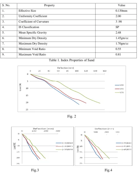
Table 1. Index Properties of Sand
Fig. 2
Fig.3 Fig.4
S. No. Property Value
1. Effective Size 0.130mm
2. Uniformity Coefficient 2.00
3. Coefficient of Curvature 3 .98
4. IS Classification SP
5. Mean Specific Gravity 2.68
6. Minimum Dry Density 1.45gm/cc
7. Maximum Dry Density 1.70gm/cc
8. Minimum Void Ratio 0.55
233 |
P a g e
Fig.5 Fig.6
VI. NOTATIONS
V10, V15, V20: V stand for vertical pile and 10, 15, 20 represent L/D ratio
(+30)B10, 15, 20: (+30) B represent positive batter angle and 10, 15, 20 represent for L/D ratio
(+45)B10, 15, 20: (+45) B represent positive batter angle and 10, 15, 20 stand for L/D ratio
Fig.2 represents variation of lateral load capacity of vertical piles with different L/D ratio
Fig.3 represents variation of load capacity of positive batter piles with batter angle of (+30) with different L/D
ratio
Fig.4 represents variation of load capacity of positive batter piles with batter angle of (+45) with different L/D
ratio
Fig.5 represents variation of load capacity of vertical and positive batter piles
Fig.6 represents variation of load capacity of vertical and negative batter piles.
VII. CONCLUSIONS
1.Individual positive battered micropile is more resistant to lateral loads.
2.Individual negative battered micropile is less resistant to lateral loads.
3.In case of positive battered micro piles lateral load capacity increase with increase in batter angle.
4.In case of negative battered micro piles lateral load capacity decrease with increase in batter angle.
5.Model studies have indicated larger deflection as compared to theoretical values computed by theoretical
analysis. Hence one cannot rely upon model study.
REFERENCES:
Desmukh,A.M. and Ganpule, V.T. (1990):Design and construction of mini grouted piles in Bombay region
IS 2911: Part 4 (1985): Code of Practice of Design and Construction of Pile Foundations-Load Test on Piles,
Bureau of Indian Standard , New Delhi
Karthigeyan, S.Ramakrishna, V.G.S.T and Rajagopal k.(2007) : Numerical Investigation of the Effect of
234 |
P a g e
Rajashree, S.S. and Sundaravadivelu R.(1996): Degradation Model for One way Cyclic Lateral Load on Piles
in Soft Clay
Ramakrishna V.G.S.T. (1997) : Behaviour of Pile Groups under Static and Cyclic Lateral Loading in Soft
Marine Clay
Broms. B. (1964): Lateral resistance of piles in cohesion less soil
Sabini, G. and Sapio, G. (1981):Behaviour of small diameter piles under axial load
Messad, F., Niyama S. and Rocha R.(1981): Vertical load test on instrumented root piles
Bruce, D.A. (1988,1989): Aspects of minipiling practice in the United States
Attwood, S.(1987): Pali Radice their uses in stabilization of existing retaining walls and creating insitu
retaining structures
Duncan, J., Evans, L., Jr., and Ooi, P., Lateral Load Analysis of Single Piles and Drilled Shafts, Journal of
Geotechnical Engineering, Vol.120 (6), 1994, pp 1018–1033.
Mansur C.I. & Hunter A.H., Pile tests- Arkansas River project, ASCE Journal of Soil Mechanics &