Design, Analysis and Testing of Catalytic
Converter for Emission Reduction
Utkarsh Wani1, Rohan Vekaria2, Aditya Chivate3, J.L.Minase4
B. E Student, Department of Mechanical Engineering, SCOE, Pune, India1
B. E Student, Department of Mechanical Engineering, SCOE, Pune, India2
B. E Student, Department of Mechanical Engineering, SCOE, Pune, India3
Assistant Professor, Department of Mechanical Engineering, SCOE, Pune, India4
ABSTRACT:Automobile demand is on the rise, as personal transportation freedom is major sort out luxury. This leads to problem of curbing emission level from increasing number of automobiles. Today most of the automobiles are equipped with catalytic converters which helps meet the strict emission laws of government. These catalytic converters are made of noble elements like Rhodium, Palladium and Platinum. Due scares supply and ever increasing demand for these metals their prices are sky rocketing.This work explores incorporating Nurbs design criteria for catalytic converter and using other cheaper catalyst like Nickel and Copper, to provide same functionality as noble metals. A two way catalytic converter is developed for Honda G200, 197cc engine, used in portable generators. The catalyst converter developed is tested under maximum throttle condition.The HC emission reduction is not achieved but the obtained emission are well within the permissible level as per BS IV emission norms, whilst CO emission reduction is observed in range of 82% across various speeds. This work also attempts to eliminate cold start problems using a thermal energy storage system to keep the catalytic converter hot even under engine off condition. A eutectic alloy of Mg-Zn-Al is used as the Phase Changing Material (PCM) to store the heat around the catalyst which keeps catalyst at 150oC for more than two hours.
KEYWORDS: Honda G200Engine, Nickel and Copper,Mg-Zn-Al Eutectic Alloy, Thermal Energy Storage (TES)
I. INTRODUCTION
Automobiles throughout the world are the primary consumers of fossil fuels, which emit toxic gases when burnt; including HC, CO and NOx. Catalytic converters are developed to detoxify these gases into less harmful gases such as
carbon dioxide, water and nitrogen. OEM catalytic converters are built for commercial vehicles and use noble elements including Platinum (Pt), Palladium (Pd) and Rhodium (Rh). Catalytic Converter is a cylindrical unit about the size of a small silencer and is installed into the exhaust system of a vehicle such as a car, scooter, moped, motorcycle or auto-rickshaw. It is placed between the exhaust manifold and the silencer. Inside the converter there is a honeycomb structure or wire mesh layers made up of a ceramic or metal, which is coated with alumina base materials and thereafter a second coating of precious metals platinum, palladium or rhodium or combinations of the same. This second coating serves as a catalyst.
A catalyst is a substance, which causes a chemical reaction, at lower activation energy henceforth-increasing rate of reaction. As a result of catalytic reaction, as the exhaust gases pass over the converter substrate, toxic gases such as CO, HC and NOx are converted into harmless CO2, H2 and N2. There are two types of catalytic converters; 1) Two-way
converter, which is used to control only CO and HC emissions by oxidation. 2) Three-way converter, which is used almost in all petrol cars. It controls CO and HC emissions by oxidation as well as NOx emissions by reduction.
II. LITERATUREREVIEW
As the design of the catalytic converter was engine based, shell dimensions were calculated using formulas [1]. Computational fluid dynamics (CFD) analysis was performed on catalytic converter to minimize backpressure generation inside the catalytic converter [2].Temperature distribution inside the catalytic converter were obtained using CFD analysis and from the experiment performed, it can be concluded that initial time lag of 41 sec. was required to activate the catalyst [3]. Investigation of non-noble catalyst were required to overcome the use of noble catalyst as they were available in limited amount and causes catalyst poisoning at higher temperature [4].Nickel based catalytic converter was developed. By using nickel-based catalytic converter, HC reduces to 40% and CO reduces to 35% [5]. Copper was used as a catalyst in catalytic converter.By using copper based catalytic converter it was found that HC is reduced by 38% and CO 33% at full load [6].
Phase Changing Material (PCM) was incorporated in concentrated solar power plants to improve the thermal energy storage and therefore, giving maximum efficiency. Mg-Zn-Aleutectic alloy were used. After experimental analysis, a good thermal stability was observed for at least 700 cycles [7].
Heat storage system was designed for a catalytic converter to eliminate the cold start emissions. Mg70Zn5.1Al24.9 eutectic
alloy was used for this purpose [8].
Paraffin was used as a PCM due to its high energy storage capacity, chemically inert and stable nature [9].
III.MODELLINGOFCONVERTER
The objective of this study is to determine the effect of inlet cone geometry and type of substrate on the pressure drop. Different cell shapes such as square and corrugated and cell sizes of 100 and 200 Cells per square inch (CPSI) are considered. CFD analysis enabled to observe the pressure drop in each of these shapes and sizes. The catalytic converter chamber is designed for a single cylinder, four stroke, Honda G200 engine, considering the engine specifications which are mentioned in table 3.1
Table 3.1 Engine Specifications
Space Velocity:
For a Single Cylinder Engine, Space Velocity = 30,000 ℎ
Volume Flow Rate = Swept Volume × No. of intake strokes
= × × × × 60
Catalyst Volume = 0.0007092
Shell dimensions:
Shell of the Catalytic converter holds the substrate coated with the catalyst material for the emission reduction. Assumption of length of shell is twice the diameter is selected. Diameter is calculated from volume of catalyst needed which is 0.0007092 m3.
For, Length = 2 × Diameter
Volume = Area × Length
0.0007092 = × × 2
D = 77mm and L = 154mm
IV.DESIGNFINALIZATIONBASEDONNURBSCRITERIA
Non-uniform rational basis splines have been used to generate a curve using the given constrained tangents .Using the same concept here, the 90° step has been discretised and semi polygonal structure is developed. This structure is then converted to a smooth curve. This has been done using iterative method.
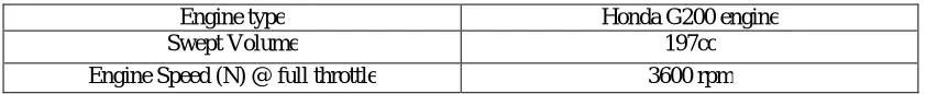
900-step outlet creates higher-pressure drop and resulting in higher backpressure inside the catalytic converter and reducing the effective emission reduction inside the catalytic converter. Fig.4.1 shows the chamber design with 900-step outlet.
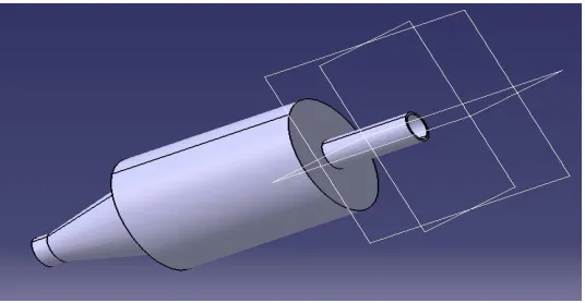
Fig 4.2 shows the discretization of 900-step outlet into the smooth curve, reducing the backpressure generation inside the catalytic converter, increasing the emission reduction.
Figure 4.2 Chamber Design With Fillet
V. CFDANALYSISONCATALYTICCONVERTER
As the performance of catalytic converter is substantially affected by the flow distribution inside the substrate, a uniform flow distribution can increase its efficiency and lower the pressure drop. The flow distribution inside a catalytic converter assembly is governed by geometric configuration of inlet and outlet cone section and the substrate and therefore a better design of catalytic converter is very important.
The main objective of CFD study is to stimulate fluid flow in a catalytic converter in order to determine:
Internal flow pattern inside the converter and its impact on flow distribution.
To determine the flow distribution over the inlet of substrate.
To determine velocity and pressure distribution across the catalytic converter.
CFD analysis is able to predict flow fields, even combined with heat transport, due to recently developed numerical algorithms. The careful choice of physical parameters like inlet and outlet boundary conditions is a pre-condition for reliable simulation results. CFD analysis have been performed on various converter designs integrated with substrates of different CPSI. The considerations for this analysis are the inlet fluid velocity, inlet temperature and outlet relative pressure. The procedure followed includes setting the boundary conditions i.e. inlet and outlet, applying the inlet velocity and temperature, providing time step and initializing the run.
Figure 5.1 Meshed Model of Catalytic Converter
Domain Conditions
:
High Reynolds number k-ε turbulence model has been used as the CFD model. This turbulence model is widely used in industrial applications. The equations of mass and momentum have been solved using SIMPLE algorithm to get velocity and pressure in the fluid domain. The assumption of an isotropic turbulence field used in this turbulence model is valid for the current application. The geometry of the element is made as hex dominant mesh, with a refined mesh near the wall. The model has approximately 0.8 million hex dominant fluid elements.The reference pressure will be set at 1.33 bar and all pressure inputs and outputs will be obtained as gauge values with respect to this. Commercial CFD solver CFX has been used for this study. It is a finite volume approach based solver which is widely used in the industries. Governing equations solved by the software for this study in tensor Cartesian form are:Continuity:
= 0
Momentum:
=− + + +
Where ρ is density, ui and uj Cartesian velocity, p is static pressure, η is viscous stress tensor.
Material: Air has been selected as a working fluid, which is assumed to be steady and compressible and considered to be operating at 3500C and 1.35 bar. The material properties under these condition are given in table 5.1
Table 5.1 Properties of Air
Property Air
Density(kg/m3) 0.7534 Viscosity(Pa.s) 3.0927×10⁻⁵ Specific heat (J/Kg-K) 1056.6434 Thermal Conductivity (W/m-K) 0.0242
Figure 5.2 Comparison between Corrugated and Square Substrate [10]
Fig. 5.3 shows the CFD of catalytic converter containing square shaped substrate to determine the pressure drop within the catalytic converter.
Figure 5.3 CFD of Square Shaped Substrate inside the Catalytic Converter to Determine Pressure Drop
Fig. 5.4 shows the CFD of catalytic converter containing corrugated shaped substrate to determine the pressure drop within the catalytic converter.
From figure 5.3 and 5.4 respectively, it is clearly seen that corrugated substrate shows better flow distribution as well as lesser pressure drop compared to square substrate. Lesser pressure drop leads to lesser backpressure generation inside the catalytic converter and increasing the emission reduction and improvising the overall efficiency of the catalytic converter.
Figure 5.5 shows CFD of square shaped substrate inside the catalytic converter to determine the velocity streamline distribution.
Figure 5.5 CFD of Square Shaped Substrate inside the Catalytic Converter to Determine the Velocity Streamline Distribution
Figure 5.6 shows CFD of corrugated shaped substrate inside the catalytic converter to determine the velocity streamline distribution.
Figure 5.6 CFD of Corrugated Shaped Substrate inside the Catalytic Converter to Determine the Velocity Streamline Distribution
with the surface of the catalyst coated substrate and thus reducing the emissions and improvising overall performance of the converter.
Table 5.2 shows the comparison between square and corrugated substrate based on Turbulence Eddy Dissipation, Pressure Drop, Effective Surface Area per Square Inch(mm2).
Table 5.2 Change In Turbulence, Pressure Drop & Surface Area With Respect To Substrate Type
Comparing the results of the CFD analysis, corrugated shaped substrate provided with 31.96% less pressure drop and better flow distribution. Also, corrugated shape exposes more surface area for catalyst coating which decreases the light-off period and activates the catalyst at a faster rate, resulting in less emissions and stable catalysis. Fig. 5.7 shows the geometry of catalytic converter.
Figure 5.7 Geometry of Catalytic Converter
VI.MATREIALANDCATALYSTSELECTIONFORCATALYTICCONVERTER
Material selection for catalytic converter body: Material selection for the catalytic converter plays a vital role due to the increased warranty requirements and regulatory compliances. Exhaust system materials should possess high temperature oxidation resistance, thermo- mechanical vibration resistance, external salt corrosion resistance and internal acid/base corrosion resistances.
The converter shell holds the internals of the converter. The materials used for the shell should provide good strength, corrosion resistance and relatively low thermal deformation. Inlet and outlet cones are either welded to converter shell or formed. These cones regulate the flow of gases. The cones are designed to maintain the uniformity index of the gas flow. As cones experience high temperature, they should possess high thermal oxidation resistance. Material should provide proper thermal property. Flange is the Component used for interlinking or connecting the exhaust system with pipes. Solid flanges provide better strength than sheet metal flanges. Material used should provide very good mechanical properties.
Based on the aforementioned requirements and availability of the material, SS 441L is used which satisfices all the required properties and thus can be used effectively.
Substrate Turbulence Eddy Dissipation
Pressure Drop
(Pascal)
Effective Surface Area per Square Inch(mm2)
Square 0.89 10.38 698.16
Material selection for substrate: Monolith and wire mesh have been selected as a material for the substrate.
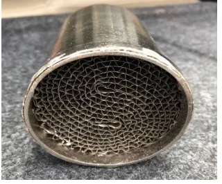
. Monolith: In our daily practice a monolith is a ceramic or metallic block consisting of a large number of small straight and parallel channels. The monoliths are made by extrusion. A special mixture of clay binders and additives is pushed through a sophisticated dye to create the monolith structure. The material is dried cut to the required length and fired at high temperatures. On the walls of the channels a catalytic active layer can be applied in which chemical reactions can take place. Because of the large number of channels the contact area between the catalytic layer and the fluid that travels inside the channels is very large. Further the channels are straight and parallel so that the flow is not obstructed and the pressure drop across a monolith is low. The monolith substrate allows high conversion efficiencies at high gaseous throughput, provides a high geometric surface area with lower pressure drop, excellent high temperature and thermal shock resistance and can be conveniently oriented in the exhaust train in any number of directions. Fig. 6.1 shows the monolith substrate.
Figure 6.1 Monolith Substrate
. Wire Mesh
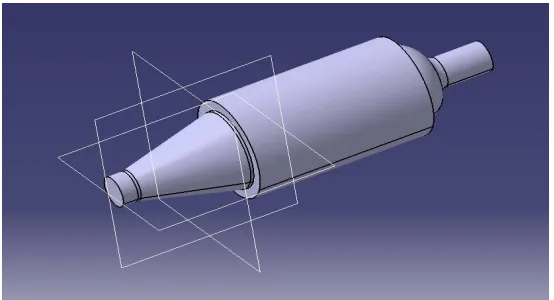
Stainless steel in the form of wire mesh has been selected as the substrate. Stainless steel has been used because of its various mechanical and chemical advantages like high temperature stability, corrosion resistance and high resistance from acid attack. Stainless steel has been Laser Cut into circular shape in order to accommodate into the converter body. Fig. 6.2 shows the wire mesh substrate.
Figure 6.2 Wire Mesh Substrate
Catalyst Selection:Generally catalytic converter uses Pt, Pd and Rh. These noble metals are known to promote the oxidation processes. There are several problems associated with noble based catalytic converter.
The failure of catalytic converter may be due to following factors such as,
Converter meltdown
Carbon deposit
Catalyst fracture
Poisoning
Though not a noble metal, copper and nickel works as a catalyst for the conversion of the pollutants in exhaust but in limited proportion. It is therefore concluded that, development of copper and nickel based catalytic converter is feasible since it has given satisfactory results for the given operating conditions and reduction of HC and CO emissions. A study has been conducted on two types of substrates which consisted of Nickel coated monolith substrate and Copper coated wire mesh. These substrates are assembled in the converter shell and the emissions have been measured with the help of the Gas Analyser equipment.
. Electroplating of monolith substrate with reducing agent Nickel (Ni)
Nickel has proved to be a younger sibling of Palladium in the field of transition metal catalysis. It has number of readily available oxidation states commonly invoked in catalysis. Ni (0)/Ni (II) catalytic cycles are wide spread but the easy accessibility of Ni (I) and Ni (III) oxidation states allows different modes of reactivity and radical mechanisms. Considering this, Ni (III) was chosen.
The Corrugated structure is coated with a 10 microns’ thick layer of Nickel that creates an extremely porous surface with a large surface area. This Corrugated structure, provides the most efficient use of materials while maximizing the surface area of the catalytic converter. It is essential that the catalytic converter has the most surface area possible so that when the automotive exhaust is directed through the converter, there is sufficient room and resources available to transform the toxins into inert gases.Fig 6.3 shows nickel coated monolith substrate.
Figure 6.3 Nickel Coated Monolith Substrate
. Electroplating of monolith substrate with reducing agent Copper (Cu)
Figure 6.4 Copper Coated Wire Mesh
VII. THERMALHEATSTORAGESYSTEMUSINGPHASECHANGINGMATERIAL
Along with the catalyst, several other components can also be incorporated to improve the performance of the catalytic converter. Components incorporated can aid the performance of catalytic converter either by storing the heat in the catalytic converter or by improving the oxygen storage capacity in the catalytic converter, or by any other means. Cold start emission has been one of the main problems in the catalytic converter. Every time the engine is started after being shut down for a long period, the catalytic converter remains in cold condition for the initial period of engine run, making the catalyst in the converter to render ineffective for the conversion. During this period, engine emits high amount of pollutants mainly the unburnt hydrocarbons which pass through the catalytic converter without being converted because of the inactivity of the catalyst at low temperatures.
In this paper, Thermal Energy Storage (TES) system has been used to store the heat in the catalytic converter and thereby reduce the cold start emission problems in catalytic converter.
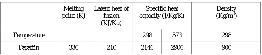
Paraffin’s have moderate latent heat, low toxicity and relatively low cost. Both the melting point and latent heat content of the materials generally increase with molecular weight. Latent heat value for paraffin is 210kJ/Kg. From the thermal point of view, paraffin’s are known to have Moderate thermal energy storage capacity, relatively constant melting temperatures close to the assumed phase change temperature, negligible sub cooling and low vapour pressure in the melting process. Furthermore, paraffin is chemically inert and stable; it does not show phase segregation, it is non-corrosive to the container material, and it is commercially available.
Disadvantage of using paraffin is they expand by almost 10-15% on melting which complicates the container design and their low specific gravity (typically 0.8-0.9) results in higher PCM volume for the heat storage. Table 7.2 shows the characteristics of paraffin wax.
Table 7.2 Characteristics of Paraffin Wax
Melting point (K)
Latent heat of fusion (KJ/Kg)
Specific heat capacity (J/Kg/K)
Density (Kg/m3)
Temperature 298 573 298
Paraffin 330 210 2140 2900 900
heat and keep the catalytic converter hot for longer time. PCM used in this paper is Mg70Z5.1Al24.9 eutectic alloy. The
characteristics of Mg70Z5.1Al24.9 alloy such that it shows the lowest melting temperature over all of the mixing ratios for
the involved components species, such an alloy is known as eutectic alloy. Mg70Z 5.1Al24.9 eutectic alloy is more suitable
for this operation because of its physical properties.
E. Risueño[7]et al.studied the physical characteristics of Mg70Z 5.1Al24.9 eutectic alloy. It has high latent heat of fusion,
high specific heat capacity and high thermal stability. It has a melting point of 3400C which is more suitable as it keeps the catalyst active for the catalytic conversion. By using the TES engine run and keep the catalytic converter hot during the engine-off period and hence reducing the cold start emission problems in catalytic converter. Table 7.3 states the characteristics of Mg70Z 5.1Al24.9 eutectic alloy.
Table 7.3 Characteristics of Mg70Z 5.1Al24.9 Eutectic Alloy
Melting point (K)
Latent heat of fusion
(KJ/Kg)
Specific heat capacity (J/Kg/K)
Thermal conductivity (W/mK)
Density (Kg/m3)
Temperature 298 573 373 573 673 298
Mg70Z 5.1Al24.9 613 157 690 830 47 59 38 2820
. Preparation of Mg-Zn-Al eutectic alloy
500g of Mg-Zn-Al eutectic alloy has been prepared by mixing the elements Mg, Zn, and Al in the proportion of 70, 24.9, and 5.1 by weight respectively. The elements are taken in a Graphite vessel and mixed properly. It is kept in the Muffle furnace, and the temperature inside the furnace was raised to 5000C and kept for 10 hours. Then, the furnace is allowed to cool. The heating and cooling cycle have been carried for one more time for homogeneous mixing of metal powders. Fig. 7.1 shows metallic powder mixture of Mg-Zn-Al before processing.
Figure 7.1 Metallic Powder Mixture of Mg-Zn-Al before Processing
Figure 7.2 Phase Changing Material after Processing
Figure 7.3 shows complete manufactured catalytic converter with incorporation of TES in an annular cylinder.
Figure 7.3 Catalytic converter with TES system
VIII. MEASUREMENTANDCALCULATIONS
Fig 7.3 TES Incorporated Catalytic Converter
Catalytic convertor is connected to engine exhaust with the help of flange to prevent exhaust gas leakage. The engine has been run on full throttle settings (3600 rpm) till light off temperature of 280°C is attained in monolith substrate. This is measured using a calibrated K-type thermocouple. The engine emissions have been measured on the gas analyser. Settling time of 30 seconds has been provided before recording data of emission. HC and CO emissions have been taken at two engine speeds i.e. starting rpm (1750) and full throttle (3600).
. Exhaust Gas Analyser
Exhaust gas analyser is used to measure the concentration of exhaust emissions from the engine. It basically consists of a probe which is inserted in the exhaust pipe of the engine and the value of concentration of the gas is directly indicated on the monitor of the analyser. Before using the analyser, it is first calibrated with the environmental conditions then it is tested for various tests like HC residue test to remove the residual hydrocarbons from previously taken reading. Then the analyser is subjected to leak test, zero adjustment, oxygen sensor test etc. Before taking the actual emission readings on the analyser, the engine is run at the particular speed for at least 2 minutes in order to ensure proper concentration of the emissions from the engine.
. Honda G200 Engine
. Muffle Furnace
Muffle Furnace has been used to heat PCM containing annular cylinder at 600°C. The cylinder is placed inside the furnace for 4 hours after attaining the desired temperature of 600°C. This helped in charging of PCM with latent heat of fusion. Annular cylinder has been removed from furnace and Nickel coated monolith substrate is placed inside the annular. Temperature of substrate is measured with help of infrared thermometer at regular interval of 5 Min for first hour, at 10 Min. for second hour and 20 Min. for rest of the time.
Two emission tests are conducted with the help of Gas analyser system to assess catalytic converter performance and determine modification required to meet BS-IV emission norms. Results have been summarized for CO and HC.The engine meets emission norms of Japan as it is manufactured in Japan but Indian emission norms vary from Japan emission norms. During the test, data is recorded for engine emissions at maximum rpm as generator works on maximum load condition.
. CO and HC Emissions
The effect of catalytic converter on CO and HC emission have been shown for setup with catalytic converter and without catalytic converter. Table 8.1 shows the comparison of CO and HC emissions with and without catalytic converter at maximum rpm.
Table 8.1 Comparison of HC and CO Emissions with and without Catalytic Converter
Engine RPM Setup CO emission (%Vol) HC (ppm)
3600 Without catalytic converter
4 348
3600 With catalytic converter
2.020 363
. Calculations of Mass of Pollutants:
This section deals with the calculation procedure of the mass emission of the pollutants. The mass emission of pollutant is calculated by formula,
= × × × × 10
Where,
= Volume of the diluted exhaust gas expressed in m3/test and corrected to standard conditions of 293 K and 101.13 KPa.
= Density of the pollutant in kg/m3 at normal temperature and pressure (293 K and 101.13 kPa)
=Humidity correction factor used for the calculation of the mass emissions of oxides of nitrogen. There is no humidity correction for HC and CO.
= Concentration of the pollutants in the diluted ehaust gas expressed in ppm and corrected by the amount of pollutant contained in the diluted air
= Distance covered in kilometers
= ×
= 293
Considering readings of speed of engine at 3600 rpm,
CO emission is 2.020%vol
HC emission is 363 ppm
Substituting value of CO emission in equation (ii),
= 5.783
= 1.145
= 20200 = 0.5
Putting the values of equations (iv), (v),(vi),(vii) in equation (i)
= 0.264
Now, substituting values of HC emission in equation (ii)
= 8 × 10
= 2.0098
= 363 = 0.5
Putting the values of equations (iv), (v), (vi), (vii) in equation (i)
= 5.443 × 10
The values of CO and HC have been calculated in g/km using above formulas for maximum engine rpm and tabulated in Table 8.2
Table 8.2 Values of HC and CO Emissions in g/km for Maximum Engine RPM.
Engine RPM Emission Standard emission level by Bharat IV Norms
(g/km)
Without catalytic converter (g/km)
With catalytic converter (g/km)
Percent Reduction
3600 CO 1 1.462 0.264 82%
3600 HC 0.1
4.729 x 10
-5
5.443 x 10
-5
. Thermal Energy Storage System
Table 8.3 shows the comparison of substrate temperature using Paraffin and Mg70Zn5.1Al24.9 thermal energy storage
system.
Table 8.3 Comparison of TES using Paraffin and Mg70Zn5.1Al24.9
Sr. No. Time Temperature of substrate in paraffin TES (°C)
Temperature of substrate in Mg70Zn5.1Al24.9 TES (°C)
1 0 25.6 25.9
2 2 67.5 115.7
3 4 102.3 155.9
4 6 122 178.1
5 8 135.8 190.4
6 10 137.3 197.6
7 12 127.4 206.3
8 14 115.7 211.5
9 16 106.2 214.6
10 18 98.1 219.9
11 20 85.7 224.4
12 22 78.6 233.2
13 24 71.3 239
14 26 63 239.5
15 28 59.1 241.2
16 30 55.8 242.9
17 35 46.7 238.4
18 40 42.3 234.5
19 45 36.4 231.7
20 50 32.1 223.4
21 55 29.8 218.6
22 60 28.2 210.5
23 70 25.4 206.7
24 80 25.4 198.3
25 90 25.4 190
26 100 25.4 181.3
27 110 25.4 173.6
28 120 25.4 164.9
29 140 25.4 152.8
30 160 25.4 144.7
31 180 25.4 138.3
32 200 25.4 133.7
33 220 25.4 128.5
34 240 25.4 123.3
. Cold start emissions
Table 8.4 shows the percentage improvement in cold start emission of CO using Paraffin and Mg70Zn5.1Al24.9
eutectic alloy at various engine running time.
Table 8.4 Difference in CO Emissions With Respect to TES System
T a b l e 8 . 5
shows the percentage improvement in cold start emissions of HC using Paraffin and Mg70Zn5.1Al24.9 eutectic
alloy at various engine running time.
Table 8.5 Difference in HC Emissions With Respect to TES System
IX.RESULTANDDISCUSSIONS
. CO and HC Emissions
The emission reduction target for this work is to achieve emission level after testing of engine and to achieve BS-IV norms as 1.00 g/km of CO, 0.1 g/km of HC which is equivalent to Euro-IV standards. Without catalytic converter CO emissions are 1.27 g/km and using designed catalytic converter CO emissions has been reduced to 0.27 g/km and lies well within the permissible range as per BS-IV norms. However, HC emissions without using catalytic converter are
4.729 x 10
-5
g/km while using catalytic converter HC emissions are 5.443 x 10
-5
g/km. Calculations performed states that CO emissions are reduced by 82%. However, the HC emission reduction is not achieved but the obtained emission are well within in the permissible level as per BS-IV norms.
Sr No. Engine Running time Cooling Time No TES CO emission Paraffin TES CO emission Percent Improvement
Mg70Zn5.1Al24.9TES
CO emission
Percent Improvement
1 15 30 2.550 2.540 0.4% 2.360 7.45% 2 30 30 2.520 2.390 5.15% 2.100 16% 3 45 30 2.450 2.150 12.25% 2.020 17.55% 4 60 30 2.430 2.020 16% 2.010 17.28% 5 75 30 2.420 2.010 16.94% 2.010 16.94% 6 90 30 2.420 2.010 16.94% 2.000 16.94%
Sr No. Engine Running time Cooling Time No TES HC emission Paraffin TES HC emission Percent Improvement
Mg70Zn5.1Al24.9TES
HC emission
. Thermal Energy Storage System
Experiment of Paraffin TES shows that cylindrical monolith substrate is placed inside and temperature of the monolith has been raised from room temperature to around 137.8°C and temperature reduced slowly thereafter. Temperature of monolith never went above 150°C.
Experiment of Mg70Zn5.1Al24.9 TES shows that as cylindrical monolith substrate is placed inside and temperature of the
monolith has been raised from room temperature to around 250°C and temperature reduced slowly thereafter. Temperature of monolith remained more than 150°C for more than 140 Min.
Paraffin TES shows that, it requires higher temperature for its activation to reduce CO during cold starting condition. Initially when engine running time has been 15 minutes with a cooling time of 30 minutes, paraffin shows only 0.4% improvement in cold start emissions. However, when engine running time is close to 45 minutes, paraffin shows 12.25% improvement in cold start emissions.
Mg70Zn5.1Al24.9 TES shows that, it activates better compared to paraffin at lower engine running time. Initially when
engine running time is 15 minutes with a cooling time of 30 minutes, it shows 7.45% improvement in cold start emissions. When engine running time is close to 45 minutes, it shows 17.55% improvement in cold start emissions. Both Paraffin and Mg70Zn5.1Al24.9 TES shows that, initially when engine running time is 15 minutes with a cooling time
of 30 minutes, percentage reduction in HC emissions remains closer to 3%. However, when engine running time is close to 45 minutes, both TES shows maximum of 6.9% improvement in cold start emissions of HC. Fig 9.1 shows the variation of temperature vs time for Paraffin and Mg70Zn5.1Al24.9 TES.
Fig 9.1Temperature vs Time for Paraffin and Mg70Zn5.1Al24.9 TES.
X. CONCULSION
. Analysing result of experiments, it can be concluded that designed catalytic converter reduces the emission of Honda G200 engine considerably. The HC emission reduction is not achieved but the obtained emission are well within in the permissible level as per BS-IV norms, whilst CO emission reduction is observed in range of 82% at maximum throttle speed i.e. 3600 rpm.
. TES system of Mg70Zn5.1Al24.9can keep catalytic converter at elevated temperature of 150°C for more than two
hours.
. TES system of paraffin can keep catalytic converter at elevated temperature of 100°C for more than 20 Min.
. Cold Start emission test shows that without incorporation of TES system, emission are high. Paraffin TES system shows that, it needs charging of TES for more than 45 Min. to give better cold start emission results. Mg70Zn5.1Al24.9 eutectic alloy showsgood results in emission reduction just after half an hour of TES charging.
FUTURE SCOPE
. Two way converter can be further developed as a three way converter by using copper oxide as catalyst, which is low cost compared to rhodium for reduction of NOx.
. Double corrugated substrate can be used to increase effective surface area and giving better results compared to corrugated substrate for reduction of HC and CO.
. Better phase changing material can be explored for higher capacity engine, which has higher exhaust gas temperature.
. Other metals can be incorporated as a catalyst, which has better efficiency for emission reduction.
. Weight reduction by using HSS430CU which proves to be lighter in weight as compared to the conventional materials used.
REFERENCES
[1] P.Karuppusamy et al. “Design, analysis of flow characteristics of catalytic converter and effects of backpressure on engine performance” IJREAT
International Journal of Research in Engineering & Advanced Technology, Volume 1, Issue 1, March, 2013 ISSN: 2320 – 8791.
[2]PL.S. Muthaiah et al. “Global Journal of Researches in Engineering” Vol.10 Issue 5 (Ver 1.0) October 2010.
[3]Joachim Braun et al. “Three diamensional simulation of the transient behaviour of a three way catalytic converter 2002-01-00665 R”.
[4] Julie M et al. “ Development of Automobile Catalytic Converter during Last Four Decades--A Review” International Journal for Research in
Applied Science & Engineering Technology (IJRASET) Volume 2 Issue XI, November 2014 ISSN: 2321-9653.
[5] M.A.Kalam et al. “Development and test of new catalytic converter” sadhana Vol.34 part 3 june 2010, pp,467-848.
[6] Chirag Amin et al. “Catalytic converter based on non- noble material” IJAERS/VOL.I/Issue II/January-March,2012/118-120. .
[7] E. Risueño et al. “Mg-Zn-Al eutectic alloys as phase change material for latent heat thermal energy storage” International Conference on
Concentrating Solar Power and Chemical Energy Systems, Solar PACES 2014.
[8] Asheesh Padiyar et al. “Reduction of cold start emissions in automotive catalytic converter using thermal energy storage system” Journal of
Chemical and Pharmaceutical Research, 2016, 8(8):1121-1125. ISSN: 0975-7384.
[9] Study on Properties of Paraffin Phase Change Energy Storage Concrete, 2012 International Conference on Future Energy, Environment, and Materials.
[10] http://www.siamindia.com/
[11] Valentine P. Ananikov, “Nickel: The ‘Spirited Horse of Transition Metal Catalysis”, ACS Catal., 2015, 5, pp. 1964-1971.
[12] S. H. Amirnordin, W. Salim “ Pressure drop Analysis of Square and Hexagonal Cells and its effects on the Performance of Catalytic Converters” International Journal of Environmental science and Development, June 2011