Performance Evaluation of FSR, LAR1 and ZRP Routing
Protocols in MANET based on RWP Mobility Model
Ria Ranjan
M.Tech ScholarAshish Xavier Das
Asst. Prof. ECE,SHIATS-DU
A.K. Jaiswal
HOD ECE , SHIATS-DUAshish Allen Roberts
M.Tech ScholarABSTRACT
Mobile Ad Hoc Networks (MANETs) are self-configuring, infrastructure-less wireless ad hoc networks. It has a routable networking environment on top of the Link Layer ad hoc network. Routing is based on multi-hop pattern from source to a destination node/ nodes. Routing protocols for MANETs have to face the challenges of frequently & arbitrarily changing topology, low transmission power and asymmetric links. In this paper different routing protocols, namely FSR, LAR1 & ZRP, are comparatively discussed on the basis of Average End to end delay, Received Through-put and Average Jitter. An outline of these protocols has been presented in this paper by comparing their functionality, benefits, characteristics, limitations and analysis. RWP (random waypoint) mobility model has been used and simulations are performed using QualNet 6.1 version Simulator from Scalable Networks.
Keywords
MANET, FSR, LAR, ZRP, RWP (random waypoint)
1.INTRODUCTION
MANET is a decentralized, peer-to-peer wireless ad hoc network, capable of configuring itself. A MANET network uses Wi-Fi or satellite transmission to connect to other networks or devices. Each device in a MANET is capable to move independently in any direction and thus can change its links to other devices frequently. Each node must forward traffic unrelated to its own use, thus functioning as a router. While configuring a MANET the primary challenge is enabling each device, to continuously maintain the information required for proper routing of the traffic. These networks may operate on their own or may be connected to larger Internet. Previously Ad-hoc networks were mainly used for military applications. Now they have become increasingly more popular within the computing industry. Its applications include virtual classrooms, meetings, casual conferences, emergency search-and-rescue operations, disaster relief operations, automated battlefield operation in hostile environments where construction of infrastructure is difficult or expensive.
In MANET there are mainly three types of unicast routing protocols: proactive routing protocols, reactive routing protocols and hybrid routing protocols. There are several proactive routing protocols available for Ad-hoc networks such as DSDV, OLSR, FSR, GSR, CGSR and IARP etc. There are also a variety of reactive routing protocols such as AODV, DSR, LAR, DYMO and IERP etc. ZRP and TORA are categorised as hybrid routing protocols.
2. ROUTING PROTOCOL
A MANET is a collection of mobile nodes that are dynamically and arbitrarily located. The interconnections between nodes are capable of changing on a continuous basis. In order to commence communication within the network a routing protocol needs to discover routes between the nodes. Correct and efficient route establishment between a pair of nodes is the primary goal of such an ad hoc network routing protocol for timely delivery of the massages. Also route establishment must be done with a minimum overhead and bandwidth consumption. There are various types of unicast routing protocols designed for ad hoc networks. Proactive routing or 'table driven' routing protocol forwards the packet to already known route by continuously evaluating the routes within the network. Each node maintains the routing information and update it consistently. Reactive protocol or 'on demand' routing protocol performs the routing process only when it is required. A route discovery is initiated by the node when no route is found. A Hybrid protocols has the benefits of proactive and reactive protocols both.
2.1 Fisheye State Routing
Fisheye State Routing[11] is a table-driven or proactive routing protocol. “Fisheye” technology was first introduced by Klein & Stevens. It facilitates the reduction of graphics and image data. The characteristic of “Fisheye” is that the information across the focal length can be clearly seen, while the information beyond it is considered vague. The FSR[8] algorithm for ad hoc networks introduces the idea of multi-level "scope" for the reduction of routing update overhead in large networks. Link State for every destination is stored in a node of the network. Link State update of a destination is periodically broadcasted to its neighbours with a frequency depending on the hop distance of the destination (i.e., the "scope" relative to that destination). State updates corresponding to the distant nodes are propagated with lower frequency than those for nearby destinations. Nodes construct a topology map of the entire network and compute efficient routes using these state updates. FSR is best suited for large scale MANETs, as the scope update scheme has the advantages of reducing routing update packet size and thus achieving high data packet to routing packet ratio.
messages are very large. The disadvantage of FSR is its limited scalability. The other disadvantages includes processing overhead and the storage complexity. FSR doesn’t provide security compared to other protocols.
Fig 1 : Scope of Fisheye
The above figure presents the fisheye’s scope specified by the centre red node. Number of hops required to arrive at a specific node is termed as scope. Information about nearby nodes are exchanged more often than for the farther nodes as the update message size is considerably less in FSR. The centre node maintains the updated information regarding the nodes present in the inner circle. As a result when the node are far away, accuracy of the information about the node decreases.
2.2 Location-Aided Routing
The Location-Aided routing protocol (LAR) is a reactive (on-demand) routing protocol that uses the location information of the mobile nodes. Dommety and Jain briefly suggested the use of location information in an ad hoc networks. Location information about nodes is obtained using Global Positioning System (GPS). LAR[15] is an advancement over DSR[16] in context of route request packet flooding. In LAR, location information of the mobile nodes are used to flood a route request packet in a forwarding zone only called as request zone instead of the entire ad-hoc network. This request zone is determined by location information of the destination. Routing overhead in an ad hoc network is reduced by the use of location information, this is one of the advantages of LAR. Complexity of protocol is nullified assuming that each node recognizes position accurately. Limitations of this protocol is every host requires a GPS device.
LAR defines two different types of request zones : LAR Scheme 1 (LAR1) and LAR Scheme 2 (LAR2).
2.3.1 LAR1 schemes (Expected zone and Request
zone)
Expected Zone
Suppose, source node (S) knows that the destination node (D) was at some position P at time t0 and current time is t1. The expected zone of the node D from the viewpoint of node S is the region that node S expects to have node D at time t1 based on the information that node D was at position P at time t0. The expected zone is only an estimation of node S for determining the possible positions of node D.
Request zone
Request zone for the route request packet forwarding is determined by the node S. An intermediate node forwards the route request packet only, if it belongs to request zone. The request zone includes expected zone and other surrounding zone around it. Routing mechanism of LAR1 is shown in fig 3.
Fig. 3 LAR1 Routing Mechanism[18]
A rectangular shape request zone is the characteristic of LAR1. Once source knows that destination node was at a position (X0, Y0) at time t0, expected zone at time t1 is defined by a circle with radius 'R = v(t1-t0)' centred at a position (x0, y0) where v is the average speed with which destination can move. Now a smallest rectangle defines the request zone that includes current source position and expected zone such that the sides of the rectangle are parallel to the X and Y axis. Source node S determines the four corners of the rectangular request zone and includes these coordinates in the route request packet when initiating the route discovery process. The neighbouring nodes which are inside the request zone only forward the route request packet further while the outer nodes just drop the packets. Destination node sends backs a route reply packet with its current location, average speed and time as soon as it receives the route request packet. Node S uses this information for a route discovery process in the future [18], [19].
2.3 Zone Routing Protocol
Zone Routing Protocol (ZRP)[6], is an example of a hybrid reactive/proactive routing protocol. It was first proposed by Haas in 1997. It has the benefits of a proactive route discovery inside node's limited neighbourhood while a reactive protocol
for interaction among neighbourhoods. The Broadcast Resolution Protocol (BRP) [10] forwards the route request. ZRP partitions the complete network into several zones. Due to overlapping of these zones ZRP is also considered as a flat protocol. Network congestion is reduced and optimal routes are
N
A B
S C
M
Expected zone
Request zone
D r
13
12
1
2 3
5 4
8
9
7 6
10 11
1
4 fisheyes scope Hop count 1
[image:2.595.314.526.262.431.2]detected with the use of these overlapping zones. Peripheral nodes are nodes with minimum distance, which is equal to the zone radius.
ZRP has two functional components IARP(Intazone Routing Protocol) & IERP(Interzone Routing Protocol). IARP[3] is function as the proactive component and requires Neighbour Discovery Protocol while IERP[4] works as the reactive component of ZRP. Hello messages identify the link failures and ensure that neighbours are present. IERP is triggered if IARP is unable to locate the destination, i.e., the destination is outside node’s zone. With correct zone size control traffic can be reduced to a minimum. Thus ZRP achieves a better performance.
On one hand, ZRP limits the scope of the proactive procedure only to the node’s local neighbourhood while on the other, the search throughout the network is global in nature. That is done by efficiently querying selected nodes in the network, instead of querying all the network nodes.
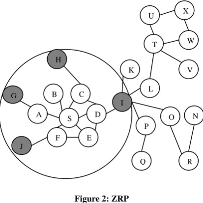
Figure 2: ZRP
The above example shows the source node S which sends packet to destination i.e. node X. This diagram has zone radius r=2. To check whether destination is within its zone, the node uses the routing table offered by IARP because if not found then route request is issued by IERP. Request is broadcasted to peripheral nodes represented gray in fig 2.
[image:3.595.65.272.289.496.2]There is a significant reduction in communication overhead and delay in this routing protocol as compared to proactive approaches. ZRP appears to be disadvantageous when the zone radius is less .Normally it performs in a proactive manner but for reduced values it acts in a reactive manner, hence the complexity of ZRP is high.
Table 1. Comparison of FSR, LAR1 & ZRP
Protocols FSR LAR1 ZRP
Category Proactive Reactive Hybrid
Routes Scope
range
Shortest path
Shortest path
Routing Indices Routing tables
Request zone & Expected zone
Interzone & Intrazone table
Multicasting abilities
No No No
Route Recouping Notify source
Notify source
Initialize repair at failure time
Multiple Paths Yes Yes Yes
Communication overhead
Low Medium Medium
Hello Msg needed
No No Yes
4. SIMULATION ENVIRONMENT
4.1 RWP (Random Waypoint) Mobility
Model
Mobility models represent the movement of mobile users, and how their location, velocity and acceleration change over time. Such models are frequently used for simulation purposes when new communication or navigation techniques are investigated.
The random waypoint model[17] is commonly used mobility model for the simulation of ad hoc networks. It is a random-based mobility model which describes the pattern of mobile users, and how their location, velocity and acceleration changes with time. In this model, the node selects an arbitrary position & moves towards it in a straight line with a constant speed that is randomly selected from a range, and pauses at that destination. The node continues this, throughout the simulation.
4.2. Simulation Setup
[image:3.595.313.541.574.730.2]We have performed simulations on QualNet 6.1 simulator[13] and performance of FSR, LAR1 & ZRP routing protocols are evaluated. Snapshot of a network in QualNet6.1 simulator is shown in figure 4 & 5.
Fig. 4 Snapshot of simulation H
G
I
J
J
B
A
C
S
F
D
E
K
P
Q O
R N L
T U
W
Fig 5. Broadcast(3D view)
[image:4.595.311.542.168.301.2]For our scenario, we have taken 1500m X 1500m dimension of space to perform the simulations and nodes are placed randomly on the space. The IEEE 802.11 [9] is used as the Medium Access Control layer protocol for wireless Local Area Networks. The number of nodes are taken as 25, 50, 75, 100, 150, 200, 250 and simulations is performed for fixed pause time. In the scenario UDP (User Datagram Protocol) connection is used, multiple CBR (Constant Bit Rate) are used as a traffic source and RWP (random waypoint) as a mobility model. Minimum velocity of nodes is taken as 0 m/s and maximum velocity of nodes is taken as 10 m/s. We have performed the simulation for 300 seconds. The simulation parameters are summarized in table 2.
Table 2. Simulation parameters
Simulation Parameter Values
Dimension 1500×1500
No. of nodes 25, 50, 75, 100, 150, 200, 250 Node placement strategy Random
Mobility model Random waypoint
Traffic source CBR
Packet size 512 Bytes
Simulation time 300sec
Channel frequency 2.4GHz
Data Rate 2Mbps
Path Loss Model Two Ray Model Physical layer radio type IEEE802.11b
MAC Protocol IEEE802.11
Antenna model Omni-directional
5. RESULTS AND DISCUSSIONS
The QualNet 6.1 network simulator has been used to analyze the parametric performance of Fisheye State Routing Protocol (FSR), Location Aided Routing (LAR1) & Zone Routing Protocol (ZRP). The metric based analysis is shown in fig. 6 to fig. 8.
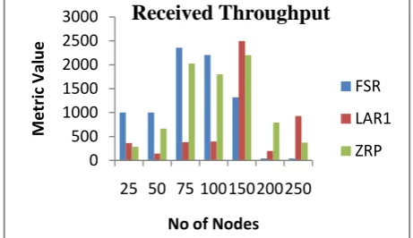
5.1 Received Throughput
The received throughput is analyzed with varying CBR data traffic. According to our simulation results better performance is shown by FSR at high mobility but in other cases it has lower received throughput. Received Throughput of FSR,
LAR1 and ZRP is increasing as the network size is increasing but FSR performs well in large sized networks. Received Throughput of ZRP is average for smaller network but for large sized network it is decreasing. It is found that FSR performs better than ZRP because of reduced routing traffic overhead in route discovery and multi level scope technique. As a result of Zone method, ZRP has not performed better than FSR.
Fig.6 Received Throughput v/s node ID
5.2 Average End-to-End Delay
[image:4.595.48.290.420.606.2]From the graphs we see that the average packet delay increases with number of nodes while routing protocols try to find valid route to the destination. Besides the actual delivery of data packets, the delay time is also affected by route discovery, which is the first step to begin a communication session .In this analysis it is observed as expected the delays are more for ZRP in comparison to FSR. Delays are incurred by ZRP’S IARP and IERP methods. The end-to-end delay of FSR is less because it has reduced routing overhead and queuing delay. Also LAR1 has variable delay with respect to node density. While ZRP shows least delay thus is better among three.
Fig.7 Average End to End delay v/s node ID
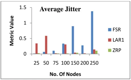
5.3 Average Jitter
Average Jitter is the variation in the time between packets arriving, caused by network congestion, timing drift, or route changes. Average Jitter should be small for a routing protocol to perform better. Thus ZRP outperforms FSR & LAR1. FSR shows worst performance for higher no. of nodes.
0 500 1000 1500 2000 2500 3000
25 50 75 100150200250
M
e
tr
ic
Val
u
e
No of Nodes
Received Throughput
FSR
LAR1
ZRP
0 0.2 0.4 0.6 0.8 1 1.2 1.4
25 50 75 100 150 200 250
M
etr
ic
V
a
lu
e
No. Of Nodes
Average End to End Delay
FSR
LAR1
[image:4.595.313.543.489.624.2]Fig 8. Jitter v/s node ID
6.CONCLUSION
It is observed in the analysis that ZRP outperforms FSR & LAR1 in general for all the scenarios as it includes both the features of proactive as well as reactive protocols. ZRP is suitable for low mobility and hence it experiences very high average end-to-end delay with high mobility. ZRP maintains strong network connectivity inside the routing zones while determining remote route faster than flooding. FSR is highly suitable for dynamically changing network topology and thus the received throughput is high with high mobility of nodes. FSR reduces the size of tables which is exchanged by maintaining less accurate information about nodes farther away. The simulation study has been conducted using network simulator QualNet 6.1 for the performance comparison of FSR, LAR1 and ZRP protocols. There is an improvement in ZRP when compared to other protocols. Hence we can conclude that ZRP is best when compared to all other routing protocols.
7. ACKNOWLEDGEMENT
We would like to thank our college for providing QualNet software and also to the faculty members of ECE dept. for their continuous support and guidance . Also I would like to extend my thanks to IJCA for their support in publishing papers.
8. REFRENCES
[1] C. S. R. Murthy, B. S. Manoj, "Ad Hoc Wireless Networks: Architecture and Protocols", Ch. Routing Protocols for Ad Hoc Wireless Networks, pp. 299-364.
[2] Kuncha Sahadevaiah, Oruganti Bala Venkata Ramanaiah,” An Empirical Examination of Routing Protocols in Mobile Ad Hoc Networks” Int. J. Communications, Network and System Sciences, June 2010, 3, 511-522
[3] Haas, Z.J., Pearlman, M.R. and Samar, P., "Intra-zone Routing Protocol (IARP)," IETF Internet Draft, draft-ietfmanet-iarp-02.txt, July 2002.
[4] Haas, Z.J., Pearlman, M.R. and Samar, P., "Inter-zone Routing Protocol (IERP)," IETF Internet Draft, draft-ietfmanet- ierp-02.txt, July 2002.
[5] C.K. Toh, “Ad Hoc Mobile Wireless Networks: Protocols and Systems”, Prentice Hall PTR. 2002: 55-77
[6] Zygmunt J. Haas Marc R.Pearlman and Prince Samar, “The Zone Routing Protocol for Ad-hoc Networks”, draft-ietf-manet-zone-zrp-04.txt, July 2002.
[7] Perkins CE, Ad Hoc Networking[M]. London: Addison-Wesley, 2001.
[8] Ding Junxia and Ningbo, Simulation and evaluation of the performance of FSR Routing Protocols based on Group Mobility Model in Mobile Ad Hoc, 2001 IEEE.
[9] Azzedine Boukerche, A Performance Comparison of Routing Protocols for Ad Hoc Networks, 2001 IEEE.
[10] Haas, Zygmunt J., Pearlman, Marc R.: The Performance of Query Control Schemes for the Zone Routing Protocol, August 2001, IEEE/ACM Transactions on Networking, Vol. 9, No. 4
[11] G. Pei, M. Gerla, and T. W. Chen, “Fisheye State Routing in Mobile Ad-Hoc Networks,” In Proceedings of the 2000 ICDCS workshops, Taipei, Taiwan, Apr. 2000.
[12] Subramanya Bhat.M, Shwetha.D, Devaraju.J.T,” A Performance Study of Proactive, Reactive and Hybrid Routing Protocols using Qualnet Simulator” International Journal of Computer Applications (0975 – 8887) Volume 28– No.5, August 2011
[13] The Qualnet simulator www.scalable-networks.com
[14] ko. Young-Bae and Nitin H. Vaidya, "Location -Aided Routing(LAR) in mobile Ad hoc networks. Department of Computer Science, Texas A&M University, College Station, TX 77843-3112, USA .
[15] Parma Nand, S.C. Sharma, Rani Astya, “Traffic Load based Performance Analysis of DSR, STAR & AODV Adhoc Routing Protocol”, International Journal of Advanced Computer Science and Applications, vol. 1 No 4, pp 58-62.
[16] Bettstetter, C.; Resta, G.; Santi, P.; (2003) “The node distribution of the random waypoint mobility model for wireless ad hoc networks,” IEEE Transactions on Mobile Computing, vol. 2, no. 3, pp257- 269.
[17] David Oliver Jörg; (2003) “Performance Comparison Of MANET Routing Protocols In Different Network Sizes”.
[18] Dinesh Singh, Ashish K. Maurya, Anil K. Sarje;(2011) “Comparative Performance Analysis of LANMAR, LAR1, DYMO and ZRP Routing Protocols in MANET using Random Waypoint Mobility Model,” 3rd IEEE International Conference on Electronics Computer Technology (ICECT 2011), Kanyakumari, India.
0 0.5 1 1.5
25 50 75 100 150 200 250
M
e
tr
ic
Val
u
e
No. Of Nodes
Average Jitter
FSR
LAR1
![Fig. 3 LAR1 Routing Mechanism[18]](https://thumb-us.123doks.com/thumbv2/123dok_us/8073154.780177/2.595.59.275.135.401/fig-lar-routing-mechanism.webp)