Novel Method of Image Compression using Angular
Domain Concept to Achieve High Compression Rate
Pravin B. Pokle
Research Scholar,B.D.C.O.E., Sewagram, Dist.Wardha
Narendra G. Bawane
, Ph.D.
Principal, S.B.J.Instt. Of Engg., Managt. andResearch, Nagpur
ABSTRACT
Image compression plays vital role in the field of the corporate world, entertainment industry, multimedia, education communications and even at home. The main objective of Image compression is to minimize the size of image in bytes by reducing the redundancy of the image data without degrading the quality of image that results in the reduction of file size so that more images can be stored in a given amount of disk or memory space and also reduces the time required to send the images over the network. Inspired by the recent advancements in the image compression techniques, we proposed an image compression framework based on the pixel-wise fidelity. The proposed method is used to reduce the bit rate of the pixels of the image for the compression by using angular transformation. In the proposed algorithm we used the normalization technique and the inverse sine transformation to get the optimized and compressed image as an output. Finally the results are compared with different methods for MSE, PSNR and the visual appearance after decoding of image.
Keywords
Image compression, Normalization, Angular transform, Bit plane slicing, MSE, PSNR.
1.
INTRODUCTION
In fast growing world of science and technology, image compression is in demand since last few decades and since ever its demand has not fallen down. Image compression is a technique of reducing the number of bits by minimizing the redundancy between neighboring pixels in an image file [1]. Many researchers have been develop and presented different ideas and algorithms to improve the performance measures in past decade in order to achieve the better performance and quality. Among all, the proposed methods are either in frequency domain or in time domain. The disadvantage of using frequency domain is that the low frequencies pixels are discarded whereas in time domain the image size is reduce after compression. However every algorithm has its own advantages and disadvantages due to nature of each scheme. It is clear that amongst all the proposed schemes, discrete cosine transform is easy for implementation, understanding and more advantages if it is applied to JPEG standards. Another technique which is more recently developed is Vector Quantization. The performance of Vector Quantization is directly proportional to the vector size and codebook size [2]. This means with increase in vector size, the codebook size also increases which results in exponential increase in encoding complexity. In this paper we proposed the scheme based on angular transformation for the better image compression. In this scheme we consider angular position of each pixel under a sine wave by converting every pixel into angle by taking inverse sine of the normalized value of pixels. A bit plane slicing is used for further compression of image data. The main objective of this paper is to develop a new
compression technique in angular domain in order to achieve high compression ratio without degrading the original image quality.
2.
PROPOSED METHOD
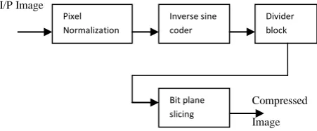
In this paper we proposed and develop a new concept for image compression using angular transformation. The compression is achieved in four steps i.e. image normalization, Angular transformation using inverse sine coder, divider block and Bit plane slicing.
Figure 1 below shows the complete image compression system.
I/P Image
Compressed
Image
Fig.1: Complete Image Compression scheme
In this work, all the pixels in the input image are first normalized and after that we applied angular transformation for converting pixels into respective phase angle and subsequently performed division so as to reduce bit rate. Finally bit plane slicing is used for further compression of image [3].
3.
COMPRESSION STEPS
This method involves four main steps for compression of given input image. Steps include pixel normalization, Inverse sine transformation, and Divider block and Bit plane slicing.
3.1
Normalization of Pixel
In image processing, the term normalization is a process of converting the range of pixel intensity values. With the help of normalization, the gray level values are converted to certain range that between 0 to 1 that is good enough for improvement in image brightness and contrast. In this research, we adopt image normalization as used in[4], where gray level value for each pixel is compared with maximum gray level value in an image.
Let pmax and pmin be the maximum and minimum gray level value in an image Pij respectively. Then equation for normalization becomes:
Qij = (Pij - pmin ) / ( Pmax - pmin) ………….(1) Where Qij is the normalized gray level values of pixels. The approximate equation for normalization is yields to:
Pixel Normalization
Inverse sine coder
Divider block
[image:1.595.316.542.332.425.2]Qnorm. =
𝑃𝑖𝑗
𝑃 𝑚𝑎𝑥 …………(2)
For example, if we consider 5 x 5 image as shown below:
Pij =
180 200 197 250 198 165 243 176 199 220 120 189 221 245 195 180 176 229 212 147 167 134 172 178 189
Here the maximum and minimum gray level values are 250 and 120.So in order to convert into normalized values we can divide each pixel by the maximum value of gray level[5]. Finally after normalization we get following matrix:
Qij =
0.72 0.80 0.79 1.00 0.79 0.66 0.97 0.70 0.79 0.88 0.48 0.75 0.88 0.98 0.78 0.72 0.70 0.91 0.85 0.59 0.67 0.53 0.69 0.71 0.75
From the above matrix it is seen that all the gray level values are converted between 0 and 1.
3.2
Angular Transformation
[image:2.595.63.272.371.468.2]Now we have the normalized image which value ranges from 0 to 1. So we can create a sin wave of the normalized image as shown in fig 2.
Fig. 2: Sine wave of the Normalized image
We know that the sine transform has the property that for two different angles, it has same gray level value. Since we know the inverse sine function is represented by sin-1 which is defined to be the inverse of the restricted sine function[6]:
i.e. sin x ,- 𝜋
2≤ 𝑥 ≤ π
2 ….…..(3)
For the assigned sequence P(n), angular transform is given by: 𝑃 𝑗 = 𝑁+12 𝑁𝑖=1𝑝 𝑖 𝑠𝑖𝑛
𝑗𝑖𝜋
𝑁+1 … . ..… (4)
And the inverse is given by : 𝑝 𝑖 = 𝑁+12 𝑁𝑗 =1𝑃 𝑗 𝑠𝑖𝑛
𝑘𝑖𝜋
𝑁+1 ...(5)
Thus the inverse sine of the normalized image can be obtained with the help of following formula:
Q
ij’ = sin
-1(Q
ij)
...(6)Where Qij is the normalized image.
Thus we can convert all the gray level values into corresponding angular values. Thus the resulting matrix is given as:
Qij′ =
4651°° 76 55°° 52 44°° 90 52°° 52 62°°
29° 48° 62° 78° 51°
46° 44° 65° 58° 36°
42° 32° 44° 45° 48°
Thus for representing the original image the value of pixels are 0 to 255 which requires 8 bit, but after taking inverse sine of normalized image, we need 7 bits for representation as it have the angular values from 0 to 90[7].
3.3
Bit Rate Reduction using Divider Block
In order to convert the image into 6 bit form for further compression, we now divide the image by 1.5 because the range of 0 to 90 after division will become 0 to 60 this will reduce the bit rate of the image[8].
Thus we have; Qij" = 𝑄𝑖𝑗 ′
1.5 ………(7)
Qij" =
3134°° 50 36°° 34 29°° 60 34°° 34 41°°
30° 21° 27° 34° 22°
30° 29° 43° 38° 24°
28° 21° 29° 30° 32°
Here the maximum value of angle is 60, for which 26 = 63 and hence we can represent it in 6 bits.
3.4
Bit Plane Slicing
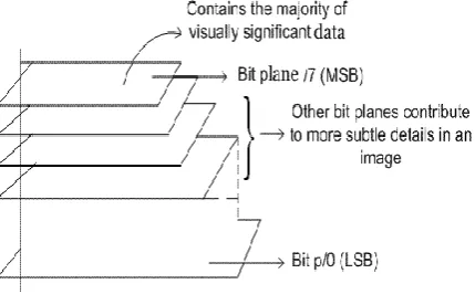
[image:2.595.322.537.446.584.2]Again the output obtained from divider block is processed with the help of bit plane slicing so that further compression of an image can be achieved. A bit plane is a set of bits corresponding to a given bit position in each of the binary numbers in an image. It is used to determine the adequacy of numbers of bits used to quantize each pixel in the image [9].
Fig.3: Bit Plane slicing for 8 bit image
From figure 3, it is seen that instead of highlighting gray level images, it is desired to highlight the contribution made to total image appearance by specific bits. Suppose that each pixel in an image will be represented by 8 bits. Assume that the image is composed of 8, 1-bit planes ranging from bit plane1-0 (LSB) to bit plane 7 (MSB)[10].
In Qij" we have 6 bits compressed image, now we apply the bit plane slicing technique on Qij" image.
46 101110 10111(5 bit form)
Fig. 4: 1bit, 2 bit bit plane slicing
Suppose the original 8 bit input image is of size 100kb. So when we apply the 0 bit bit plane slicing on Qij" image the output image will be 2/8 of the original image i.e. we are able to compressed the size of image to 25%. For 1 bit bit plane slicing the output image will be 3/8 of the original image i.e. we are able to compress the image to 37.5%. For 2 bit bit plane slicing the output image will be 4/8 of the original image i.e. we are able to compress the image to 50%.Thus in this proposed method we are able to compressed an image upto 50 %.
4.
EXPERIMENTAL RESULTS
In this section, we present the experimental results of the proposed method based on several experiments involving real image data. The set of experiments evaluate the effect of different methods on the quality of the reconstructed image.
Experiments were conducted using the standard data base
such as images „lena‟, „Football‟,„Lotus‟and Cutebaby. The
performance measures for analysis used is mainly Mean square Error (MSE), Peak Signal to Noise Ratio (PSNR), Compression Ratio and Image Quality[12]. Here MSE is the cumulative squared error between the compressed and the original image. Whereas PSNR is a measure of the peak error. For evaluating mean square error and peak signal to noise ratio we use the following formulae[13].
MSE = 𝑋𝑌 1 𝑋𝑖=1. 𝑌𝑗 =1( Qij - Qij”) 2
...(8) PSNR = 20* log 10 ( 𝑀𝑆𝐸255 ) ...…..(9) Where Q(i,j) is the original image and Q(i,j)” is the compressed version of the image and X,Y are the dimensions of given image, 255 is the peak signal value.
(a) (b) (c)
(d) (e) (f) Fig. 5: (a) Original lena image (b) Reconstructed image
using DCT (c) Reconstructed image using RLE (d) Reconstructed image using Huffmans (e) Reconstructed
image using wavelet dB2 filter (f) Reconstructed image using proposed method.
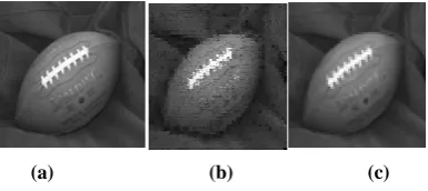
(a) (b) (c)
(d) (e) (f) Fig.6: (a) Original image (b) Reconstructed image using
DCT (c) Reconstructed image using RLE (d) Reconstructed image using Huffmans (e) Reconstructed
image using wavelet dB2 filter (f) Reconstructed image using proposed method.
(a) (b) (c)
(d) (e) (f) Fig.7: (a) Original image (b) Reconstructed image using
DCT (c) Reconstructed image using RLE (d) Reconstructed image using Huffmans (e) Reconstructed
image using wavelet dB2 filter (f) Reconstructed image using proposed method.
(a) (b) (c)
(d) (e) (f)
Figure 8: (a) Original Cutebaby image (b) Reconstructed image using DCT (c) Reconstructed image using RLE (d) Reconstructed image using Huffumans (e) Reconstructed image using wavelet dB6 filter (f) Reconstructed image
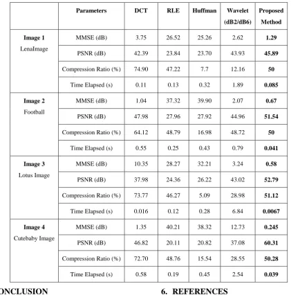
[image:3.595.318.539.217.397.2] [image:3.595.321.535.444.624.2] [image:3.595.55.277.453.625.2] [image:3.595.72.265.685.771.2]Table I: Comparison of results for different images for different parameters Parameters DCT RLE Huffman Wavelet
(dB2/dB6)
Proposed Method Image 1
LenaImage
MMSE (dB) 3.75 26.52 25.26 2.62 1.29
PSNR (dB) 42.39 23.84 23.70 43.93 45.89
Compression Ratio (%) 74.90 47.22 7.7 12.16 50
Time Elapsed (s) 0.11 0.13 0.32 1.89 0.085
Image 2
Football
MMSE (dB) 1.04 37.32 39.90 2.07 0.67
PSNR (dB) 47.98 27.96 27.92 44.96 51.54
Compression Ratio (%) 64.12 48.79 16.98 48.72 50
Time Elapsed (s) 0.55 0.25 0.43 0.79 0.041
Image 3
Lotus Image
MMSE (dB) 10.35 28.27 32.21 3.24 0.58
PSNR (dB) 37.98 24.36 26.22 43.02 52.79
Compression Ratio (%) 73.77 46.27 5.09 28.98 51.12
Time Elapsed (s) 0.016 0.12 0.28 6.84 0.0067
Image 4
Cutebaby Image
MMSE (dB) 1.35 40.21 38.32 12.73 0.245
PSNR (dB) 46.82 20.11 20.82 37.08 60.31
Compression Ratio (%) 72.70 48.76 15.54 28.55 50.28
Time Elapsed (s) 0.58 0.19 0.45 2.54 0.039
5.
CONCLUSION
For compression of images many researchers have been proposed various algorithms and techniques. In this paper we propose an efficient method based on angular domain concept. The proposed method is developing in MATLAB and simulating the methods for MMSE, PSNR and compression ratio. The experimental results shows the proposed method works very efficiently and effectively and the results obtained are extremely good. For comparison, we use standard existing methods such as DCT, RLT, Huffmans and Wavelet with dB2 and dB6 filters with proposed method and performance measures consider are MMSE, PSNR, Compression ratio and visual quality of the reconstructed image. It is seen that the overall percentage of compressed image is 50.00 % which is a very high compression rate. Also the visual quality of output image is intact and hence is exactly as same as input image. Moreover, the Peak Signal to Noise ratio (PSNR) value obtained is very high and is in between 50 dB to 60 dB and minimum mean square error (MMSE) value is very low and comes out to be 0.245 for image cutebaby. Moreover, from the table 1 it is clear that performance measures obtained are very good enough to show the high success rate of the research being done by means of this paper.
6.
REFERENCES
[1] Shantanu D. Rane and Guillermo Sapiro, Member, IEEE,”Evaluation of JPEG-LS, the New Lossless and Controlled-Lossy Still Image Compression Standard, for Compression of High-Resolution Elevation Data”, IEEE Transactions on Geoscience and Remote sensing, VOL. 39, NO. 10, Oct. 2001
[2] Kadono, S, Tahara O and Okamoto N (2001) “Encoding ofcolor still pictures wavelet transform and vector quantization”, Canadian Conference on Electrical and Computer Engineering 2:931–936
[3] I.Hontsch and L. J. Karam, “Adaptive image coding with perceptual distortion control,” IEEE Trans. Image Processing, vol. 11, pp. 213-222,March 2002.
[4] R. Cilibrasi, P. M. B. Vitanyi; “Clustering by Compression”, IEEE Transaction on Information Theory, vol. 51, N° 4, April 2005, pp 1523 - 1545.
[6] J.Shi and J. Malik, ―Normalized cuts and image segmentation, IEEE Trans.PatternAnal.Mach.Intell., vol. 22, no. 8, pp. 888–905, Aug. 2000.
[7] C. en Guo, S.-C. Zhu, and Y. N. Wu, “Towards a mathematica theory of primal sketch and sketchability,” in Proc. IEEE Int.Conf. Computer vision (ICCV’03), 2003, pp. 1228–1235.
[8] C.C. Chang and J. C. Chuan, “An image intellectual Property Protection scheme for graylevel images using visual secret sharing strategy,” Pattern Reconition Letters, vol. 23, pp. 931-941, June 2002.[9]
[9] M.Mohammed Sathik, "Feature Extracton on Color ED x-Ray Images by Bit-plane Slicing Technique", International Journal of Engg. Science and Technology, Vol. 2(7), 2010, 2820-2824.
[10]Z. Zhang , W.Li & B. Li, “An Improving Technique of Color Histogramam in Segmentation Retrieval.”2009 Fifth International Conference on Information Assurance and Security, 381 -384(2009).
[11]Mr. N S T Sai and R. C. Patil, Image Retrieval Using Bit-Plane Pixel Distribution, International Journal of Computer Science and Information Technology, Vol.3, June 2011.
[12]Aksay et al., “End –to -end stereoscopic video streaming with contentadaptive rate and format control,” Signal Processing: Image Communication, vol. 22, pp. 157 - 168, 2007.
[13]A. B. R. H. S. a. P. E. S. Z. Wang, "Image quality assessment: from error visibility to structural similarity," IEEE Trans. Image Processing, vol. 13, no. 4, pp. 600- 612, 2004.