Dispatch Strategy for Grid-connected Micro-wind
Turbine Generators with Battery: Case Study in Malaysia
S M Suboh
1,2,*, N H Baharudin
1,3, O A Basheer
11School of Electrical Systems Engineering, Universiti Malaysia Perlis, Malaysia
2School of Information Technology and Electrical Engineering, University of Queensland, Australia 3
Centre of Excellence for Renewable Energy (CERE), School of Electrical Systems Engineering, Universiti Malaysia Perlis, Malaysia
Received October 4, 2019; Revised December 18, 2019; Accepted December 24, 2019
Copyright©2019 by authors, all rights reserved. Authors agree that this article remains permanently open access under the terms of the Creative Commons Attribution License 4.0 International License
Abstract
In recent years, Malaysian government has been searching for an opportunity to realize the first wind farm in Malaysia to achieve 20% penetration of renewable energy by 2025. Even though Malaysia experiences low average wind speed, but rapid advancement of micro-wind turbine technology promises a potential enhancement of wind harvesting in Malaysia in the near future. Concerning of high wind penetration to the grid, severe technical problems because of its fluctuating and intermittent nature will affect the power system stability. In view of that, this paper proposes a dispatch strategy for a wind farm comprising micro-wind turbine generators supported by a battery to minimize the fluctuation where for a monthly interval, a different value of reference power is followed. In parallel, the lower and upper constraints of battery state-of-charge must be satisfied. The proposed strategy is validated using the real wind data measured at Mersing, Malaysia. The results reveal that the proposed strategy successfully reduces the fluctuation and achieves the reference power for most of the intervals while ensuring the battery operates within a safe operating region. Using the simulation results, the payback period is estimated, which exposes that this project as an example, requires about 20 years of period to reimburse the capital expenditure.Keywords
Dispatch Strategy, Micro-wind Turbine Generator, Battery, State-of-charge, Payback Period1. Introduction
World electricity generation, including Malaysia, is highly dependent on fossil fuels despite the fact that over-consuming may lead to severe air pollution emissions. For that reason, green energy resources, also known as renewable energy (RE) such as wind, solar, biomass, and hydropower, is explored extensively. Alongside their cleanliness, they also offer lower costs and naturally replenished. Among these resources, wind energy is one of
the most favorable prospects for its lower cost of investment, hence widely studied in Malaysia since the 1980s [1]. Nonetheless, the average wind speed in Malaysia is low, thus creating a great challenge for commercial wind power generation. Concerning this issue, appropriate wind turbine generators (WTGs) that can cope with such wind conditions should be chosen. Micro-type WTG seems to be the best option and will be applied in this study. RE related issues in Malaysia are managed by the Sustainable Energy Development Authority (SEDA) including a monitor and review of the Feed-in Tariff (FiT) system [2].
Furthermore, the main drawback of wind power is its fluctuating and intermittent characteristics, which might drive serious technical issues i.e. voltage instability and frequency control problems if a large amount of wind power penetrates into the existing grid [3, 4]. Therefore, these problems should be resolved before (if possible) a large capacity of wind power is integrated into the Malaysian National Grid. Battery storage is reported to be one of the potential solutions to mitigate fluctuation and intermittency [5]. By using a battery, steady-state wind power can be produced and dispatched, hence capable of reducing negative impacts on the grid. These hybrid systems, however, entail an effective strategy to achieve the best possible outcomes. The aim of this paper is to propose a dispatch strategy for a wind farm equipped with a battery to supply wind power to the grid with minimal fluctuation. The strategy's main components will be an approach to determine optimum reference dispatch power,𝑃𝑟𝑒𝑓based on the forecasted wind speed plus, the battery control approach for safety operation to reduce the life cycle degradation. A case study is conducted using the monthly mean wind speed data measured at Mersing weather station in 2009. The performance of the proposed dispatch scheme is observed via several simulation studies.
available in the market namely the Infiniti 300 (Figure 1) will be considered. In the datasheet, the manufacturer also has provided the amount of power the WTG can produce at a particular wind speed [8]. Therefore, the power curve as shown in Figure 2 can be plotted accordingly. All the important parameters of the Infiniti 300 are presented in Table 1. As shown in the table, this WTG will start to rotate and generate power at low wind speed which is at 2.5 m/s (also referred to as cut-in wind speed). Otherwise, the output power of WTG can also be estimated using the following formula [6]
𝑃𝑤𝑖𝑛𝑑= 0.5𝜌𝜋𝑅2𝑣𝑤3𝐶𝑝(𝜆, 𝜃) (1) where ρ denotes the air density, R is the rotor radius, 𝒗𝒘 is the wind speed in m/s and 𝑪𝒑(𝝀, 𝜽)is the WTG power coefficient as a function of 𝝀 and 𝜽, which are respectively the tip-speed ratio and the blade pitch angle.
Table 1. WTG parameters
Rated power 300 W
Cut-in wind speed 2.5 m/s
Rated wind speed 12 m/s
Cut-out wind speed 20 m/s
Rotor diameter 1.12 m
2.2. Battery Dynamic Model
It is well-known that battery storage is very useful in reducing power fluctuation. Typically, a commercial battery is built-in with a battery management system to ensure the battery operates in a safe range for prolonging battery lifetime. Its major function is to control the 𝑆𝑂𝐶, whereby in this study the safe range is set in between 20% (𝑆𝑂𝐶𝑚𝑖𝑛) to 100% (𝑆𝑂𝐶𝑚𝑎𝑥). 𝑆𝑂𝐶 can be estimated using coulomb counting method such as follows [4]:
Figure 1. The Infiniti 300 [2]
where 𝑺𝑶𝑪𝟎, 𝜼𝒆𝒇𝒇 and 𝑰𝒃𝒂𝒕𝒕 refer to the 𝑺𝑶𝑪 initial value, coulombic efficiency and battery current respectively. Considering a battery with specific rated power 𝑷𝒃𝒂𝒕𝒕(𝒓𝒂𝒕𝒆𝒅) that could supply for 𝑻𝒃𝒂𝒕𝒕 hour of duration has been installed. Therefore, its capacity, 𝑸𝒃𝒂𝒕𝒕 can be represented as
𝑄𝑏𝑎𝑡𝑡= 𝐼𝑏𝑎𝑡𝑡(𝑟𝑎𝑡𝑒𝑑) × 𝑇𝑏𝑎𝑡𝑡 (3) where the rated battery current, 𝐼𝑏𝑎𝑡𝑡(𝑟𝑎𝑡𝑒𝑑)is obtained from
[image:2.595.334.547.78.218.2]𝑃𝑏𝑎𝑡𝑡(𝑟𝑎𝑡𝑒𝑑) /𝑉𝑏𝑎𝑡𝑡(𝑟𝑎𝑡𝑒𝑑). The battery parameters are listed in Table 2.
Table 2. Battery Parameters
Rated power Rated voltage Rated current Capacity
𝜂𝑒𝑓𝑓 𝑇𝑏𝑎𝑡𝑡
1500 W 24 V 62.5 A 125 Ah 0.92
2 h
3. Proposed Dispatch Strategy
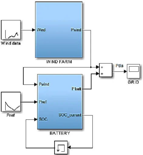
Figure 3 illustrates the configuration of wind farm equipped with battery connected to the grid in the proposed manner. The main objective is to send wind power to the grid with less fluctuation while attempting to achieve a certain target level of dispatch power with the aid of battery. In the meantime, the battery 𝑆𝑂𝐶 constraints are also to be satisfied.
3.1. Monthly Target Dispatch Power
Plenty of methods have been recommended in the literature for dispatch power scheduling such as an average, min-max and optimal method to name a few [10, 11, 12]. It should be mentioned that these methods require wind forecast data for scheduling. Based on the forecasted wind speed, wind power can be forecasted accordingly. The average method is practiced in this study, whereby 𝑃𝑟𝑒𝑓 for every interval is determined by averaging the forecasted wind power for the month (consider forecasting at least a month ahead). In this case, since monthly mean wind speed data is available, 𝑃𝑟𝑒𝑓 for a single WTG can be obtained directly from the power curve in Figure 2. Meaning that,
[image:2.595.316.547.390.454.2] [image:2.595.64.292.459.541.2] [image:2.595.117.241.679.772.2]Figure 3. Block-diagram overview of the proposed dispatch scheme
3.2. SOC Feedback Control Approach
[image:3.595.190.426.79.334.2]As can be seen in Figure 3, 𝑆𝑂𝐶 feedback control approach is suggested in the battery controller. This is to ensure the battery is only effective within 𝑆𝑂𝐶 safe operating region. In addition, the controller inputs also include 𝑃𝑤𝑖𝑛𝑑 and 𝑃𝑟𝑒𝑓. Figure 4 demonstrates in detail the proposed battery regulation. Assuming 𝑃𝑤𝑖𝑛𝑑 is measurable, hence, the required battery power, 𝑃𝑏𝑎𝑡𝑡 can be calculated from
Figure 4. Battery control approach
𝑃𝑏𝑎𝑡𝑡= 𝑃𝑤𝑖𝑛𝑑− 𝑃𝑟𝑒𝑓 (4) In practice, 𝐼𝑏𝑎𝑡𝑡 can be controlled to get the desired 𝑃𝑏𝑎𝑡𝑡. In this case, 𝑉𝑏𝑎𝑡𝑡 is assumed constant at 𝑉𝑏𝑎𝑡𝑡(𝑟𝑎𝑡𝑒𝑑) thereby voltage drop is neglected. Thus, 𝐼𝑏𝑎𝑡𝑡 that will be adjusting the 𝑆𝑂𝐶 dynamic in equation (2) is directly calculated from𝑃𝑏𝑎𝑡𝑡 / 𝑉 𝑏𝑎𝑡𝑡. Positive 𝑃𝑏𝑎𝑡𝑡 and the corresponding 𝐼𝑏𝑎𝑡𝑡 reflect charging whereas negative for discharging. In the end, the total active power, 𝑃𝑑𝑖𝑠 delivered to the grid is equal to
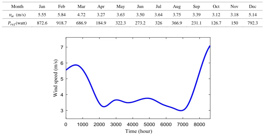
[image:3.595.164.445.450.670.2]Figure 5. Wind speed profile for a year
4. Case Study and Simulation Results
To demonstrate the performance of the proposed dispatch scheme, simulation studies are performed in MATLAB/Simulink. Real wind data with a 1-month resolution measured at Mersing is used [7]. Then, the data has been spline interpolated into a time-series data-set as displayed in Figure 5. It should be expected that the real wind data will not be as smooth as the graph. It shows that during early and end of the year, the wind flows at high speed, but quite low in the middle of the year. These significant variations happened due to the two monsoon wind seasons experienced by Malaysia. The simulation studies are conducted for 8640 hours to simulate a year period of wind data. Let’s consider the wind farm contains ten micro-WTGs. With the consideration that all the installed WTGs are identical, their specifications as described in Section 2. In the meantime, wind speed that hit each turbine is also assumed to be equal whereby wake effect is ignored. Therefore, the total
𝑃𝑟𝑒𝑓 at every interval for that wind farm can be simply multiplied by ten. That means the total capacity of wind farm is 3000 W. Both wind speed data and the corresponding 𝑃𝑟𝑒𝑓 are tabulated in Table 3.
4.1. Wind Power Dispatched to the Grid
The wind power is allegedly dispatchable such as the other conventional generators if a certain amount of power could be delivered to the grid as requested by the transmission operator system in fulfilling the demand. In this paper, 𝑷𝒓𝒆𝒇 is referred to as the power demand that can be updated monthly. Thus, by following 𝑷𝒓𝒆𝒇 as close as possible, the wind power dispatchability is improved. All the associated powers are plotted in Figure 6. The blue line represents the
total power dispatched to the grid. It demonstrates that assisted by the battery, steady-state power is achieved at the specific 𝑷𝒓𝒆𝒇 for most of the intervals. In the other words, the power fluctuation has been minimized as well as its the dispatchability. 𝑷𝒘𝒊𝒏𝒅 generated by the wind farm is plotted in the red line. Obviously shown that by averaging the wind power of a particular interval, an optimum 𝑷𝒓𝒆𝒇 is obtained, hence only a small volume of 𝑷𝒃𝒂𝒕𝒕 is needed to compensate for the power mismatch. The power mismatch, so-called ∆𝑷 is computed from∆𝑷 = 𝑷𝒅𝒊𝒔− 𝑷𝒓𝒆𝒇. ∆𝑷in the figure is plotted in the green dotted line. Positive value denotes extra power is delivered to the grid, whilst the negative value means less power is delivered to the grid; as compared to𝑷𝒓𝒆𝒇.This ∆𝑷 is produced due to the updated battery 𝑺𝑶𝑪 is either at the minimum or maximum level. Consequently, the battery is turned off to protect from over-charging or over-discharging.
[image:4.595.74.536.89.327.2]Figure 6. 𝑃𝑤𝑖𝑛𝑑 (red), 𝑃𝑟𝑒𝑓 (black),𝑃𝑑𝑖𝑠 (blue) and ∆𝑃 (dotted green)
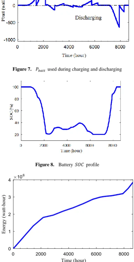
Figure 7. 𝑃𝑏𝑎𝑡𝑡 used during charging and discharging
Figure 8. Battery 𝑆𝑂𝐶 profile
Figure 9. Energy dispatched to the grid
Finally, the total energy dispatched to the grid over the year is summed up and plotted in Figure 9. Approximately 3.85 MWh has been produced by the ten micro-WTG in the windfarm supported by the battery with the available wind speed at Mersing.
4.2. Estimation of Payback Period
There are numerous ways to calculate an economic value for a certain project such as with a simple payback (SP), net present value (NPV) and internal rate of return (IRR) analysis [13]. In this work, the most common way, an SP (also called payback period) analysis is conducted using the following formula [14]
SP = total capital expendituretotal revenue (6)
SP defines the time required to recover the amount of investment. As for now, Malaysia has not yet developed any wind farm because of the wind speed limitation, there is no capital expenditure (CAPEX) has been recorded in any publication that can be referred to. Thus, information from [15] is taken where the author has claimed that CAPEX for a small-scale wind farm in Malaysia is around RM12,500 /kW. This assumption is made based upon the cost data taken from the invoices by the manufacturers. Meanwhile, the battery price is estimated at $685.5/kWh (regardless of the installation cost) which is around RM2875/kWh. As referred in Table 2, a 3 kWh battery is utilized in this system.
[image:5.595.71.281.296.432.2] [image:5.595.69.286.337.760.2]unappealing to the investors. Nevertheless, the rapid advancement of micro-WTG technology in the market promises a potential enhancement of wind power harvesting in Malaysia, although at low wind speed. Competition among manufacturers in addition, possibly reduces the upcoming cost of wind farm development hence will reduce the payback period.
REFERENCES
[1] N. Sanusi, A. Zaharim, and S. Mat. Wind energy potential: A case study of Mersing, Malaysia, ARPN J. Eng. Appl. Sci., vol. 11, no. 12, pp. 7712–7716, 2016.
[2] Sustainable Energy Development Authority Malaysia (SEDA), Available online: http://seda.gov.my/, Accessed: 28-Sep-2019.
[3] H. Ouyang, P. Li, L. Zhu, Y.Hao, C. Xu and C. He. Impact of large-scale wind power integration on power system transient stability, IEEE PES Innovative Smart Grid Technologies, Tianjin, 2012, pp. 1-6.
[4] D. Y. C. Leung and Y. Yang. Wind energy development and its environmental impact: A review, Renew. Sustain. Energy Rev., vol. 16, no. 1, pp. 1031–1039, 2012.
[5] R. Sharma, R. Yan, and M. Kearney. Predictive control of wind turbines with storage, 2013 Aust. Control Conf., pp. 177–182, 2013.
[6] S. M. Suboh and R. Sharma. Control Strategy of Wind Turbine Generator with Storage in Short-term Dispatch Scheme, 2017 IEEE PES Innovative Smart Grid Technology Conferences, Auckland, pp. 1-6.
[7] M. R. Islam. Assessment of Wind Energy Potential Mapping for Peninsular Malaysia, Thesis, 2011.
[8] Solar Power Mart, Available online: https://solarpower-mart.com/wind_turbine/300w_wind_turbi ne, Accessed: 25-Sep-2019.
[9] S. M. Suboh and R. Sharma.Robust Control of Wind Turbines under Uncertain Wind Speed Measurements,2019 IEEE PES GTD Grand International Conference and Exposition Asia, Bangkok, pp. 927–932.
[10]S. Teleke, M. E. Baran, S. Bhattacharya, and A. Q. Huang.Optimal Control of Battery Energy Storage for Wind Farm Dispatching, IEEE Trans. Energy Convers., vol. 25, no.
![Figure 1. The Infiniti 300 [2]](https://thumb-us.123doks.com/thumbv2/123dok_us/8753965.892509/2.595.117.241.679.772/figure-the-infiniti.webp)