1
www.arpnjournals.comPERFORMANCE OF STAR PATCH ANTENNA ON A PAPER SUBSTRATE
MATERIAL
WAN NOOR NAJWA WAN MARZUDI1,ZUHAIRIAH ZAINAL ABIDIN1, SAMSUL HAIMI DAHLAN1, KHAIRUN NIDZAM RAMLI1, MUHAMMAD RAMLEE
KAMARUDIN2
1Research Center for Applied Electromagnetics, UniversitiTun Hussein Onn Malaysia, 86400 Parit Raja,
Johor, Malaysia
2Wireless Communication Centre (WCC), Universiti Teknologi Malaysia, 81310, Skudai, Johor, Malaysia
E-Mail: [email protected]
ABSTRACT
This paper presents the performance of the antenna on a paper substrate material. The antenna consists of star patch and two L-stub added on the star patch to achieve lower band frequency. It has been shown that the sustainable paper substrate has a widest impedance bandwidth of 84% from 2.45 GHz to 6 GHz. Moreover, the antenna performance comparison in terms of impedance bandwidth and antenna gain using different substrates have been discussed. The antenna performances characteristics are given in terms of reflection coefficient, impedance bandwidth, antenna gain, surface current distribution, VSWR and radiation pattern. In addition, a parametric study is conducted to facilitate the design and optimization process.
Key words: Paper Material Patch Antenna Wireless Applications
INTRODUCTION
Recently, wearable antenna has gain much interest among researchers due to great demand for remote health care medical systems. It is not only employed in medical field but also in military application which requires the integration of these antennas on military clothing. The wearable antenna integrates cloth into communication system, making electronic devices less obstrusive [Liu. N. et.al., 2011, Jaiwal S. K., 2014]. Generally, wearable antenna is constructed on sustainable substrate materials such as paper and textile. Furthermore, wearable antenna is required to be light weight, low cost, flexible, resistant to shock and vibration, and maintenance free. It is noteworthy that microstrip patch antenna is the best candidate for wearable antenna due to all the requirements [Balanis, C. A, 2012, Kuo, Y. L and Wong, K. L, 2003, Samsuzzaman, M. et.al., 2013].
Previous research using sustainable substrate material such as paper and textile for wearable antenna with various shapes of patch antenna have been reported. A jeans substrate material [Al-Ashwal, W.A.M. et. al., 2015, Sundarsingh, E. F. et. al., 2014], flannel and and jeans [Rahim, M. K. A. et. al., 2012], and polyster material [Ha, S. J. et. al., 2012] were proposed in the literature. Theoretically, the fabric substrate material that has low dielectric permittivity will minimize the surface wave loss and enhanced the impedance bandwidth of the antenna [Ahmad. S., et. al, 2012]. Wearable antenna using paper based substrate developed with inkjet printed EBG array and UWB antenna was discussed in details by [Kim, S., 2012 and Shaker, G., 2011]. The relative permittivity and the thickness of the substrate material are two significant factor of the antenna performances [ Shakhirul, M. S., et.al., 2014].
In this paper, the proposed antenna was constructed on a sustainable substrate material while the radiating element and ground plane was made from copper
tape. Hence, three different substrate materials were investigated by using FR4, Rogers and paper substrate in terms of impedance bandwidth and antenna gain. By introducing star patch antenna, wideband performances can be realized. Two L-stubs were added on the patch to obtained the lower part of the frequency band. In order to enhance the bandwidth of the antenna, rectangular slit was cut on the ground plane. Details of the proposed antenna design, measured and simulated results of the fabricated prototype are presented and discussed in the following sections.
ANTENNA DESIGN
Antenna Design Concept
The topology of the antenna is shown in Figure 1. The proposed antenna was manufactured on paper substrate with dielectric permittivity of 1.75, loss tangent of 0.06 and a thickness of 0.27 mm similar in [Salleh, W. N. Z. W. et. al., 2013]. It is fed with a 50-Ω microstrip line. The overall size of the proposed antenna is 40 x 23 mm2. The proposed
2 2.5 3 3.5 4 4.5 5 5.5 6 -30
-25 -20 -15 -10 -5 0
Frequency (GHz)
Re
fle
ct
io
n
Co
e
ff
ici
e
n
t
(d
B
)
Star Patch Triangular Patch
Antenna Model and Analysis
In general, the design and construction of the star patch antenna consists of a star patch to be placed at the top of paper substrate material; partial ground plane with slit etched on the centre of ground plane beneath the paper substrate material. By introducing a star patch antenna and a partial ground plane, wide impedance bandwidth can be achieved which covers the frequency bands from 3.08 – 6 GHz. This antenna is denoted as a reference antenna. The L-stub on the patch and slit on the ground plane are introduced to cover the lower frequency bands and enhanced the bandwidth of the proposed antenna. In order to clarify the underlying mechanisms that influence the impedance bandwidth and to obtain an optimal design, the parametric studies of the antenna response to the L-stub and slit on the ground plane have been analysed.
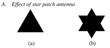
A. Effect of star patch antenna
The star patch antenna (as seen in Figure 2(b)) is performed from the iteration of the triangle patch design (Figure 2(a)). The resonance frequency [Vishwakarma, R. K. et. al., 2013] of the triangular patch can be obtained using the following equation:
f
r=
2𝑐
3 𝑆𝑒𝑓𝑓√ɛ𝑒𝑓𝑓
(1)
where:
S
eff= S
1+
ℎ
√𝜀𝑒𝑓𝑓
ɛ
eff=
𝜀𝑟+1
2
+
𝜀𝑟−1
4
(1 +
12ℎ𝑆1
)
[image:2.595.53.550.70.240.2]-1/2
Table 1: Abbreviations and expensions.
Abbreviations Expensions
fr Resonant frequency (GHz)
Seff Effective side length of the
triangle (mm)
ɛr Substrate relative permittivity
H Substrate thickness
ɛeff Effective relative permittivity
S1 Side length of the triangle
(mm)
Figure 3 shows the comparison between triangular and star patch. The dotted line demonstrated the simulated S11 of the
star patch, while the solid line shows the simulated S11 of
[image:2.595.313.548.343.478.2]the triangular patch. There is a minor differences of impedance bandwidth between star and triangular patch antenna. The triangular patch give an impedance bandwidth from 3.1 – 5.9 GHz, meanwhile star patch have an impedance bandwidth from 3.08 – up to 6GHz.
Figure 3: Simulated reflection coefficient, S11between star
and triangular patch
A. Effect of L-Stub
The L-stub are configured as shown in Figure 1(a). The use of the stubs should improve the impedance bandwidth of an antenna [Song, K., 2010] and decrease the frequency to lower frequency band. Figure 4 shows the reflection coefficient, S11 response. It can be seen that, the
introduction of L-stub symmetrically on the patch could lower the frequency band but somehow it deteriorate the upper frequency band. Therefore, in order to achieve back lower band frequency, the small rectangular slit etched on the centre of the ground plane is introduced.
B. Effect of slit on the ground plane
The small rectangular slit was etched on the centre of the ground plane to enhance the bandwidth [Pei, J. et. al., 2010, Marzudi,W. N. N. W, 2014]. The introduction of this slit broaden the impedance bandwidth of the antenna from 37.8% (2.48-3.636 GHz) to 84% (2.45-6 GHz). The comparison of reflection coefficient, S11 with and without
slit is plotted in Figure 5. Figure 6 depicts the simulated reflection coefficient, S11 of various dimensions of length of
slit, Ls. From Figure 6, it can be observed that when the Ls
starts to increase, it will effect the bandwidth of the
(a) (b)
Figure 2: (a) Basic structure of triangular patch; (b) First iteration of triangular patch.
(b) (a)
[image:2.595.61.255.478.563.2]2 2.5 3 3.5 4 4.5 5 5.5 6 -30 -25 -20 -15 -10 -5 0 Frequency (GHz) Re fle ct io n Co e ff ici e n t (d B )
Antenna with L-stub Reference antenna
2 2.5 3 3.5 4 4.5 5 5.5 6
-30 -25 -20 -15 -10 -5 0 Frequency (GHz) Re fle ct io n Co e ff ici e n t (d B ) without slit with slit
2 2.5 3 3.5 4 4.5 5 5.5 6
-30 -25 -20 -15 -10 -5 0 Frequency (GHz) Re fle ct io n Co e ff ici e n t (d B ) Ls=1mm Ls=3mm Ls=5mm Ls=7mm Ls=9mm
2 2.5 3 3.5 4 4.5 5 5.5 6
-40 -30 -20 -10 0 Frequency (GHz) Re fle ct io n Co e ff ici e n t, S 1 1 ( d B ) FR4 Substrate Paper Substrate Rogers Substrate antenna. The optimal dimension of Ls was set to 9 mm
[image:3.595.45.284.122.263.2]which gave a relative bandwidth of 84% compared to other values.
Figure 4: Simulated reflection coefficient, S11 with and
[image:3.595.45.287.195.631.2]without L-stub.
Figure 5: Simulated reflection coefficient, S11 with and
[image:3.595.312.556.210.415.2]without slit.
Figure 6: Simulated reflection coefficient, S11with various
Ls.
ANTENNA PERFORMANCE USING DIFFERENT SUBSTRATE MATERIALS
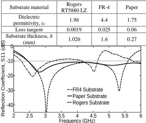
Material characterization of substrate material is a critical consideration in antenna design. Thickness, dielectric permittivity and loss tangent of substrate material play an important role in determining the loss and bandwidth performances of an antenna [Schaubert, D. H, et. al., 1989, Garg, R., et. al. (2001)]. The different between the conventional substrate material which are Rogers RT 5880LZ and FR-4 epoxy and sustainable paper substrate are
compared. The details of these substrates are listed in Table 2.
Figure 7 shows the comparison of the simulated |S11| using
different substrate materials; FR-4, Rogers and paper. It can be seen from Figure 7 that the paper substrate give a better impedance bandwidth covering 2.45 – 6 GHz with a return loss, S11< -10 dB. It is proven by [Waterhouse, R., (2003)],
that low dielectric permittivity substrate material could enhance the achievable bandwidth of the antenna.
Figure 7: Comparison of simulated |S11|on different
substrate materials.
RESULT AND DISCUSSIONS
Impedance Bandwidth
The prototype of the proposed antenna design is shown in Figure 8. The copper tape was used as a radiating element and connected by using SMA connector. To validate the simulated result, the fabricated antenna was measured using Rohde & Schwarz ZVB14 vector network analyzer. In Figure 9, the comparison between the simulated and measured result of the proposed antenna have shown.. According to the results, the frequency of the measured S11
is slightly shifted to the right with the marginally change on the bandwidth performance between the simulated and measured result. The measured result cover the frequency
Substrate material Rogers
RT5880 LZ FR-4 Paper
Dielectric
permittivity, ɛr 1.96 4.4 1.75
Loss tangent 0.0019 0.025 0.06
Substrate thickness, h
(mm) 1.026 1.6 0.27
Table 2: Substrate material
(a) (b)
[image:3.595.50.285.392.604.2] [image:3.595.304.549.479.637.2]from 2.66 – 4.48 GHz and 4.58 – 6 GHz compared to simulated which covered the operating frequency from
Figure 10: Measured and simulated radiation patterns for the proposed antenna at (a) 2.4 GHz, (b) 2.5 GHz, (c) 3.5 GHz, (d) 5.2 GHz, (e) 5.5 GHz and (f) 5.8 GHz . Left in (x-z plane) and right in (y-z plane). oooo measured
co-polar, xxxx measured cross polar, ___simulated co-polar,- - - -simulated cross polar. (a)
(c) (b)
(d)
(e)
2 2.5 3 3.5 4 4.5 5 5.5 6 1
2 3 4 5 6 7
Frequency (GHz)
V
S
W
R
2 2.5 3 3.5 4 4.5 5 5.5 6
-1 0 1 2 3 4
Frequency (GHz)
A
n
te
n
n
a
G
a
in
(
d
B
i)
FR4 Substrate Rogers Substrate Paper Substrate 2.66 – 4.48 GHz and 4.58 – 6 GHz compared to simulated
[image:5.595.310.540.142.389.2]which covered the operating frequency from 2.45 – 6 GHz. The minor discrepencies are expected due to the changes of the material properties and measurement tolerances.
Figure 9: Comparison between simulated and measured result.
Radiation Patterns
Radiation characteristics of the proposed antenna also considered. The comparison between simulated and measured far-field radiation patterns are tested at six frequencies; 2.4, 2.5, 3.5, 5.2, 5.5 and 5.8 GHz as shown in Figure 10. The patterns are tested in the x-z (E-Plane) and y-z (H-Plane) planes. It can be seen that the radiation patterns show nearly omnidirectional patterns in both planes. The results are desirable over the entire frequency bands.
Voltage Standing Wave Ratio (VSWR)
[image:5.595.50.280.161.297.2]The simulated voltage standing wave ratio (VSWR) for the proposed antenna is shown in Figure 11. It can be seen that low VSWR (< 2) is achieved over the entire frequency band from 2.4 GHz to 5.8 GHz.
Figure 11: Simulated VSWR of the proposed antenna.
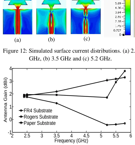
Surface Current Distributions
The simulated surface current distribution of the proposed antenna over different frequencies; 2.4, 3.5 and 5.2 GHz depicted in Figure 12. At 3.5 GHz, the surface current starts to distribute to the L-stub covering lower band frequency.
Figure 12: Simulated surface current distributions. (a) 2.4 GHz, (b) 3.5 GHz and (c) 5.2 GHz.
Antenna Gain
Figure 13: Antenna gain comparison between different substrate.
The simulated antenna gain between different substrate materials is plotted in Figure 13. As shown in Figure 13, paper substrate material have a stable gain compared to others. The antenna gain levels obtained are about 1.8 – 2.2 dBi in the range of 2.4-3.5 GHz and 3–3.3 dBi at 5.2 – 5.8 GHz. The gain increases as the frequency increases.
ACKNOWLEDGEMENT
The authors of this paper wish to acknowledge the funding of this project by Ministry of Education Malaysia (MOE) under Research Accularation Collaborative Effort (RACE) Vot No. 1510.
CONCLUSION
In this work, microstrip star patch antenna embedded on paper substrate material is presented. The proposed antenna design was made from paper substrate material while the radiating element and ground plane were made from copper tape. It is shown that the antenna achieved a relative bandwidth of 84% over 2.448 – 6 GHz with a return loss less than < -10 dB. Moreover, simulation results showed that the proposed antenna design has a wider impedance bandwidth and higher gain compared to the FR4 and Rogers substrate. Overall, this paper has demonstrated that it is possible to manufacture an antenna on sustainable substrate material and can be a suitable candidate for wearable antenna. Later, the needs to consider this proposed design function properly with human body condition will be investigated.
2 2.5 3 3.5 4 4.5 5 5.5 6
-35 -30 -25 -20 -15 -10 -5 0
Frequency (GHz)
Re
fle
ct
io
n
Co
e
ff
ici
e
n
t,
S
1
1
(
d
B
)
Simulated Measured
[image:5.595.43.278.532.672.2]REFERENCES
Al-Ashwal, W. A. M., Ramli, N. K., Mohamud Shire, A., (2015). Performance of ultra-wideband wearable antenna under severe environmental conditions and specific absorption rate (SAR) study at near distances. ARPN Journal of Engineering and Applied Sciences, 10(4), pp. 1613-1622.
Liu, N., Lu, Y., Qiu, S., Li, P., (2011). Electromagnetic properties of Electro Textile for Wearable Antennas. Applic.FrontElectr.Electron.Eng, 6,pp.553-556.
Jaiswal, S.K., Pathak, R.S., Shukla, A., Singh, V.K. (2014). A compact dual band E-shape microstrip antenna for wireless application. International Journal Recent Innov.T.Comput.Comm. 2(9).
Balanis, C.A., (2012). Antenna Theory: Analysis and Design, Wiley-Interscience, New York, NY, USA
Kuo, Y.L and Wong, K.L. (2003). Printed double T-monopole antenna for 2.4/5.2 GHz dual band WLAN operations. IEEE Transactions on Antennas and Propagation, 51(9), pp.2187-2192.
Samsuzzaman, M., Islam, M.T and Mandeep, J.S. (2013). Parametric analysis of a glass micro fibre reinforced PTFE material, multi band, patch structure antenna for satellite applications. Opto-electronics and Advanced Material Rapid Communications, 7, pp.760-769.
Shakhirul, M.S., Jusoh, M., Ismail, A.H., Kamarudin, M.R., Yahya, R., Yasin, M.N.M., Sabapathy. (2014). 1.575 GHz Circular Polarization Wearable Antenna with three different substrate materials. IEEE Asia Pacific Conference on Applied Electromagnetic.
Ahmad, S., Saidin, N.S and Che Isa, C.M. (2012). Development of embroidered sierspinski carpet antenna. Asia-Pacific Conference on Applied Electromagnetic.
Kim, S., Ren, Y.J., Lee,H., Rida,A., Hikolaou, S., Tentzeris, M.M. (2012). Monopole Antenna with inkjet printed EBG array on paper substrate for wearable application, IEEE Antennas and Wireless Propagation Letters, 12.pp.663-666.
Shaker, G., Naeini, S.S., Sangary, N., Tentzeris.M. (2011). Inkjet printing on Ultrawideband (UWB) antennas on paper based substrates, IEEE Antennas and Wireless Propagation Letters 11.pp.111-114.
Sundarsingh, E.F., Velan, S., Kanagasabai, M., Sarma, A.K., Raviteja, C., Alsath, M.G.N. (2014). Polygon-shaped slotted dual-band antenna for wearable applications, IEEE Antennas and Wireless Propagation Letters.13.pp.611-614.
Osman, M.A.R., Rahim, M.K.A., Samsuri, N.A., Elbasheer, M.K., Ali, M.E. (2012).UWB wearable textile antenna.JurnalTeknologi (Sciences &Enginnering).58 Suppl 1.pp.39-44.
Ha, S.J., Jung, Y.B., Kim, D.H and Jung., C. (2012). Textile patch antennas using double layer fabrics for wrist-wearable applications.Microwave and Optical Technology Letter.000(000).pp.2697-2701.
Salleh, W.N.Z.W., Ismail, M.Y., Misran, N., (2013). Miniaturized paper based substrate microstrip antenna with slot configurations for automotive systems, International Conference on Instrumentation, Communications, Information Technology and Biomedical Engineering.pp.100-104.
Vishwakarma, R.K., Ansari, J.A., Meshram, M.K.. (2006). Equilateral triangular microstrip antenna for circular polarization dual-band operation, International Journal of Radio & Space Physics, 35.pp.293-296.
Song, K., Yin, Y.Z., Wu, Y.B. (2010). Bandwidth enhancement of open slot antenna with a T-shaped stub. Microwave and Optical Technology Letters,52.pp.390-393.
Pei, J., WanG, A., Cai, X. (2010). A novel dual band printed antenna with a defected ground plane for WLAN applications, Antennas and Propagation AND em Theory (ISAPE), 9th International Symposium on IEEE. pp. 185-188.
Marzudi, W.N.N.W., Abidin, Z.Z., Muji, S.Z.M., Yue, Ma., AbdAlhameed, R.A. (2014). Wideband G-Shaped slotted printed monopole antenna for WLAN and WiMAX applications, International Journal on Electrical and Informaticz Engineering. 6(3).pp.596-605.
Schaubert, D.H., Pozar, D.M., Andrian, A. (1989). Effect of microstrip antenna substrate thickness and permittivity: comparison of theories with experiment. IEEE Transactions on Antennas and Propagation. 37(6), pp.677-682.
Garg. R., Bhatia, P., Bahl, I and Ittipoboon, A. (2001) Microstrip antenna design handbook, Artech House, London.