- A THEORETICAL, NUMERICAL AND EXPERIMENTAL APPROACH
A Thesis submitted for
The Degree of Doctor of Philosophy
by
HONG-BO WANG, MSc, BEng
Department of Civil Engineering and Construction University of Salford
Manchester, M5 4VVT England
TABLE OF CONTENTS PAGE
TABLE OF CONTENTS i
ACKNOWLEDGMENT iv
DECLARATION v
ABSTRACT vi
CHAPTER 1: INTRODUCTION
1.1 General Introduction 1
1.2 Scope and Contents 5
CHAPTER 2: FINITE DIFFERENCE MODELLING OF A PANEL
2.1 The Governing Equation 10
2.2 Explicit Formulation of FDM for a Multi-layer Panel 12
2.3 Unexposed Side Heat Transfer Coefficient 18
2.4 Fire Boundary Conditions 21
CHAPTER 3: FINITE DIFFERENCE MODELLING OF A PIPE
3.1 1-D Formulation of FDM for a Multi-layer Pipe 27 3.2 2-D Formulation of FDM for a Multi-layer Pipe 31
3.3 Internal Heat Exchange 34
CHAPTER 4: MODELS FOR POLYMER COMPOSITES AND INTUMESCENT COATINGS
TABLE OF CONTENTS ii
4.2 Model for WR Glass Polyester Laminate 43
4.3 Special Treatment for WR Phenolic Laminate 50 4.4 Model to Predict the Thermal Response of GRP Pipes 55
4.5 Model for Intumescent Coatings 60
CHAPTER 5: EFFECTS OF INTRINSIC PROPERTIES OF
MATERIALS
5.1 Conventional Thermal Properties 65
5.2 Effects of Moisture Content 69
5.3 Kinetic Parameters for Pyrolysis 78
CHAPTER 6. FIRE TEST RESULTS AND THE VERIFICATION OF NUMERICAL MODELLING
6.1 'Traditional' Fire Resistant Panels 89
6.2 WR Glass-Fibre Reinforced Polyester Laminates 95 6.3 VVR Glass-Fibre Reinforced Phenolic Laminates 101
6.4 Glass-Reinforced Plastic Pipes 103
6.5 GRP Pipes with Intumescent Coatings 105
6.6 Conclusions 107
CHAPTER 7: COMPUTER PROGRAM DEVELOPMENT FOR FDM 124
CHAPTER 8. HEAT TRANSFER CALCULATION USING FEM
8.1 Introduction 128
8.2 Finite Element Computer Program Development 129 8.3 Composite Concrete/Steel Deck Slab Exposed to Fire 130
TABLE OF CONTENTS
8.3.2 Moisture Effects 134
8.3.3 Thermal Properties of Materials 136
8.4 Numerical Results and Comparisons 137
CHAPTER 9. EXPERIMENTAL AND COMPUTATIONAL
APPROACHES 148
9.1 Fire Resistance Tests 149
9.2 Computational Approach 152
CHAPTER 10: SUMMARY AND CONCLUSIONS
10.1 Present Study 156
10.2 Future Development 164
LIST OF MAIN REFERENCES 168
SUPPLEMENT: DESCRIPTION OF THE FIRE TEST FACILITIES
ACKNOWLEDGMENT
The author wishes to express his grateful thanks to Professor John M. Davies, for his supervision, guidance and encouragement throughout the period of study, also for the review of this thesis.
Sincere thanks are due to Dr. John McNicholas and Dr. Raheef Hakmi for their helpful advice and support.
Acknowledgement is made to the multi-sponsor research programme on "The Cost Effective Use of Fibre-Reinforced Composites Offshore", which is supported by the UK Marine Technology Directorate Ltd, EPSRC and a consortium of companies, for their financial support. These industrial sponsors are: Admiralty Research Establishment, AGIP(UK), Amerada Hess, Ameron by, Amoco Research, Balmoral Group, Bow Valley Petroleum, BP Exploration, BP Research, Brasoil, British Gas, Ciba-Geigy, Conoco, Defence Research Agency, Dow Rheinmunster, Elf(Aquitaine), Elf(UK), Enichem(SPA), Exxon, Fibreforce Composites, Hunting Engineering Ltd, Kerr McGee Oil(UK) Ltd, MaTSU, Marine Technology Directorate Ltd, Mobil Research and Development, Mobil North Sea Ltd, Norsk Hydro, UK Ministry of Defence(Navy), UK Offshore Supplies Office, Phillips Petroleum, Shell Expro, Statoil, Total Oil Marine, UK Department of Energy, VSEL and Vosper Thornycroft.
V
DECLARATION
None of the material contained in this thesis has been submitted in support of an application for another degree or qualification of this or any other university or institution of learning.
Hong-Bo Wang
ABSTRACT
This thesis describes a theoretical, numerical and experimental heat transfer study of components of construction exposed to fire.
Within the computational aspects of the work, one and two-dimensional finite difference and finite element methods have been developed to determine the transient temperature distributions in the cross-section of elements of construction subject to furnace fire tests. Either Cartesian or cylindrical polar coordinates can be used in order to conform to the shape of the element to be analyzed. The convective and radiative heat transfer boundary conditions at the exposed and unexposed sides of components can be simulated. Structures may comprise several materials each having thermal properties varying with temperature. They could be made of traditional construction materials, for example steel, concrete, plasterboard, or novel fire-resistant composite materials, for instance Glass-Reinforced Plastics (GRP) or intumescent coatings. The critical role of the thermal properties of materials with respect to the heat transfer rate was reviewed and the factors which significantly affect the heat transmission, such as the moisture content in hygroscopic materials and the decomposition of plastic matrices, have been investigated in considerable detail.
vii reveal the fire-resistant performance of various materials and to verify the numerical modelling. Both the standard cellulosic and hydrocarbon time/temperature regimes have been used to simulate cellulosic and hydrocarbon fires. The comparison between the computational simulation and experimental measurements is generally excellent. In addition, a number of user-friendly, interactive computer programmes have been developed which may be used to predict the behaviour of building elements exposed to a specified fire environment.
CHAPTER
1
Introduction
1.1 General Introduction
Once human beings had learned how to create a fire, the struggle to control and fight it was started. Unexpected and uncontrolled fire can hazard our communities in a savage and extensive way, both in terms of its harm to life and its economic impact. Fire can cause fatalities and injuries, property damage, and both direct and indirect losses from fire. Design of the structure against fire attack is therefore of paramount importance in engineering practice. It demands increasing attention as the activities of humankind expand to more harsh circumstances, for example, the creation of offshore oil fields and the exploration of outer space.
CHAPTER 1 Introduction 2
the consequences of a fire. Passive fire resistance can be achieved either by the structure itself, or by a cladding, coating or free-standing system that provides fire protection and impedes the spread of fire. The choice between active and passive systems (or their combination), will be influenced by the protection philosophy, the anticipated fire type and duration, the equipment or structure requiring protection, and the time required for evacuation. In some applications, the use of passive fire protection alone will be cost-effective, and in other cases, a minimal residual protection must be provided in case the active systems fail to operate. Since structural engineering design is mainly concerned with passive fire protection, in this thesis, the computational and experimental heat transfer studies were solely concerned with the fire resistance of construction. There is no consideration of active fire fighting.
It is well known that a high temperature caused by fire can lead to the loss of strength and stability of a structure to the extent that structural collapse is possible. Between temperatures of 450°C and 750°C, most structural elements will lose their load-bearing capacity. Furthermore, this is not the only perilous hazard which may be caused by fire. Other potential problems include smoke, toxic gas and heat release, and even possible explosion. Therefore, evaluating the thermal response of structures during fire in order to minimize the hazard is of considerable concern for safety and reliability assessments in both onshore and offshore industries.
components or structures should conform to given standards of fire safety. The term 'fire resistance' is associated with the ability of an element of building construction to withstand exposure to a standard temperature-time and pressure regime without loss of its fire separating function or loadbearing function or both for a given time (as defined in BS 476:part 20 [1.1]). In general they involve placing a prototype element in a furnace (under load, if appropriate) and subjecting it to a heat onslaught, such that temperatures recorded by thermocouples placed in specific locations within the furnace follow a specified temperature-time relationship through control of the rate of fuel supply (gas or oil). The heat flux usually is not directly measured in such tests. This fire testing concept was first introduced in 1916, based on the observations of the temperatures of wood fires used in early ad hoc testing [1.3,1.4].
However, the determination of the fire resistance of a component of construction is a complicated process because of the many variables involved. These variables include fire growth and duration, temperature distributions in the components, alterations in material properties, interaction between the building elements, and the influence of mechanical loads on the structural system. Thus, although the standard test method provides a reasonably simple solution to an otherwise complex problem, its outcome can not be generalized and utilized effectively when there is a lack of an appropriate analytical tool. Furthermore, the design procedure usually involves a process of iterative redesign and testing, and the full-scale test which is required by the standards is extremely costly and time-consuming.
CHAPTER 1 Introduction 4
product developers look towards computer modelling as an economic method to supplement fire testing as a means of performance verification. Based on heat flow studies and structural analysis, and on the knowledge of the behaviour of materials at elevated temperatures, the computer-generated approach may provide the engineer with a solution of considerable practical value. The development of computational techniques in fire safety engineering has previously been somewhat ignored, but the general level of awareness in the area of numerical modelling is growing. An increasing demand has emerged for better predictive techniques based on sophisticated analysis to determine the fire resistance of the components of construction, especially those incorporating novel composite materials. Currently, non-linear structural analysis techniques are increasingly allowing engineers to predict the structural performance under a given set of time-varying temperature and mechanical loads. This will enable the most sensitive members to be identified. However, if the design is not to be over-conservative, it is necessary to be able to forecast the temperature distribution in all structural members with a reasonable accuracy.
As a number of issues are investigated in this thesis, the summary of previous research work will not be presented here. Instead, the state of the art will be outlined in each related chapter.
1.2 Scope and Contents
The exposure of a component of construction to transient heating conditions in a furnace results in the exposed surfaces receiving heat at increasing rates by radiation supplemented by convective heat transfer. The increase in the surface temperature of the components causes heat to flow to the interior and leads to physical and chemical changes in the material. Organic materials such as wood and GRP might burn, materials with a low softening temperature melt and others may suffer some physical disruptions; most will be distorted and almost all undergo a reduction in strength. Even for a fire protected structure, the structure will eventually heat up to temperatures which lead to a serious loss in stability.
As specified above, the performance of building components under fire conditions has a critical safety implication. Research and development work continue with the aim of providing the fire engineer with a design tool for obtaining a prescribed level of fire safety based on heat transfer principles. Heat transfer is concerned with the physical processes underlying the transport of thermal energy due to a temperature difference or gradient. The objective of
,WILS
CHAPTER 1 Introduction 6
temperature distribution history within a component of construction exposed to a hostile fire environment. All three distinct heat transfer modes, conduction, convection, and radiation, were given full consideration. Based on the transient temperature profile, other information such as the internal heat flow, thermal expansion/contraction, thermal stresses and potential damage to unexposed portions can be estimated.
A nonlinear transient equation which governs the heat transmission must be solved in order to predict the temperature profile in a component of construction. Since closed solutions for such equation exist only for very simple cases, numerical approaches that incorporate either the Finite Difference Method (FDM) or Finite Element Method (FEM) have generally been employed to address heat transfer problems. It is believed that FEM has advantages when dealing with complex geometry and loading but its formulae and programming are more complicated. The formulae for FDM are relatively simple, and the execution of FDM programmes is rapid. As the configurations of components under investigation are not so complicated, the finite difference method is applied in the main part of this thesis. Nevertheless, a two-dimensional finite element model is also developed.
One or two-dimensional Cartesian or Polar coordinates were used to accommodate various configurations of components. Whereas the thermal response and mechanical behaviour of structures subject to a heating process may be interrelated, this coupling has been neglected in this stage. Initially, it is the accuracy of the thermal modelling which normally presents the major problem.
The finite difference formulation for a multi-layer panel system is derived in Chapter 2. The modelling of the boundary conditions on the unexposed and exposed sides due to radiative and convective heat exchange are established.
In Chapter 3, the one and two-dimensional finite difference equations for multi-layer pipe systems are formulated. The internal heat transfer coefficient is calculated for the case of a pipe filled with flowing fluid. For two-dimensional problems, the formulae for heat exchange in the inside of an empty pipe are also outlined.
CHAPTER 1 Introduction 8
The decisive role of the thermal properties of material relating to the heat transfer rate is reviewed in Chapter 5. These include the conventional thermal properties, moisture content and kinetic parameters of decomposition. Those values which were used in the numerical calculations are enumerated. The significant influence of moisture content on heat transfer is investigated and a new model is developed.
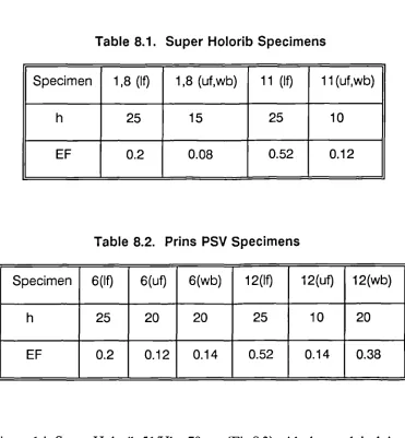
The experimental verification of the FD formulations and the modelling of the fire boundary conditions, moisture effects and decomposition are presented in Chapter 6. In order to reduce the cost and time, a model-scale technique is used. The specimens include traditional construction panels, sandwich panels, GRP laminates, GRP pipes, and GRP pipes with intumescent coatings. Their performances under standard fire tests are obtained and experimental and theoretical results are compared.
Chapter 7 presents a description of the development of user-friendly, interactive computer programmes. The functions and capabilities of these fire-dedicated programmes are also illustrated.
Another powerful and popular numerical method, finite element analysis, is exploited for two dimensional problems in Chapter 8. An excellent agreement is obtained between the computational results and test results on representative examples.
design. The main aim is to assure the fire safety at a reasonable cost.
10
CHAPTER
2
Finite Difference Modelling of a Panel
2.1 The Governing Equation
In order to evaluate the fire resistance performance of a component of construction, it is necessary to know the temperature history of the component during exposure to fire. The natural starting-point for discussion about temperature distribution calculation in a structure is Fourier's Partial Differential Equation for heat flow by conduction. The general unsteady-state equation governing heat conduction in Cartesian coordinates is[2.1]:
OT 0
ar
0 07' (3 8TP Cp at = —
8c kM—)+—ac(D—)+--(1c(D—)(3x ay ay az az
where
T(x,y,z,t) is temperature (°C);
k(T) is temperature dependent conductivity(W/m°C); is density (kg/m3);
Cp is specific heat (J/kg°C); is time (sec);
x,y,z are the Cartesian coordinates.
The right hand side of equation (2.1) represents the net heat conduction in a solid, while the left hand term represents the sensible energy accumulated. The materials are assumed to be homogeneous and isotropic. The study of conductive heat transfer is principally concerned with the solution of (2.1). As mentioned above, with complicated geometries and boundary conditions, the solution can be obtained only by an approximate numerical method.
The finite difference method is comparatively simple in conception and inherently suited to the approximate solution of heat conduction through sections subjected to a prescribed rate of heat impact. FDM replaces the derivatives in equation (2.1) with approximations in the form of finite-sized differences between values at particular locations. The following two approaches can be used[2.1] to transfer the governing partial differential equation into the corresponding finite difference equation:
a). Mathematical replacement technique b). Physical energy balance technique
CHAPTER 2 FDM of a Panel 12
of the point is then computed, based on the specific heat and mass of material in a particular cell:
Mass of control cell x Specific heat x Rate of change of node temperature
= Net heat flow to cell (22)
2.2 Explicit Formulation of FDM for a Multi-layer Panel
The FDM approaches to heat transfer problems can be classed as either explicit or implicit methods. The implicit method has to solve a simultaneous system of algebraic equations at each time step, whilst the explicit method yields the temperature at a given time level directly from previously computed values. The explicit finite difference method provides an especially simple and effective procedure although it suffers from a restriction on the length of the time-step in order to maintain numerical stability. However, this does not cause significant problems in fire resistance analysis as a short time-step is necessary in order to model the very rapid temperature increase of the hot face during fire testing. Furthermore, a short time-step also results in an increase in accuracy when temperature-dependent properties are quasi-linearised.
(23)
(24)
near the edges). The one-dimensional transient governing equation of (2.1) is:
0T(x,t) _ 0 „— 071x,t)
pCp a aoc(i) a )
where 0 x L, for t> 0.
It is subject to the boundary conditions on x=0 or x=L for t>0:
T = Tg(t)
where T (t) is the known temperature on the boundary;
Or, if the boundary is losing heat to or gaining heat from an ambient temperature condition[2.1]:
51'
k(7)— = h(7)(T.,-7) + FEcr[(T.,+273) 4 -(T+273)4]
where
• is the temperature(°C) on the boundary; • is the ambient temperature(°C);
h(T) is the surface heat transfer coefficient W/m 2°C which
is dependent on the condition of problems and this will be discussed later;
• is a geometrical factor;
CHAPTER 2 FDM of a Panel 14
E is the emissivity;
a is the Stefan-Boltzmann constant (5.67x10- 8WW2K4).
The formulation of (2.5) is obtained by the energy balance technique. The first term of (2.5) on the right hand side represents the convection and the second term represents the radiation.
The initial boundary condition is:
T = To(x) for t =0 in Osx sL (26)
where To is the known initial temperature distribution.
Transferring the partial differential equation to a finite difference equation(FDE) in both space and time domains by the energy balance technique results in the explicit FDE for a layer panel. The reason for the consideration of multi-layer construction is that the use of passive fire protection normally leads to a sandwich structure. The advantages of sandwich construction include good fire insulation and corrosion resistance, weight reduction with increased strength and stiffness, substantial cost savings and the more efficient provision of increased safety and reliability.
CHAPTER 2 FDM of a Panel 15
(i) For a typical node m within one material layer:
Tv
= F0[
2(km _ion Tmi _i, +km+1,mTmi.1) i 1
+ T m(— —2)] km _tm +km+1,m F 0
where superscript i indicates the time level and Fo is Fourier number which defined by
F —
(k 1 +k 1 )At
0
2p Cp(Ax)2
To preserve the stability of calculation and in order not to violate thermodynamic principles, the coefficient (1/F0 -2) in equation (2.7) should be greater than zero. Then Fo should be less than 0.5 and this provides a restriction on the time step At. The conductivity km_/,,,, (and similarly kni+t,n) is evaluated for each step as
T i 1 + Tmi
km_i,m — k ( ni-2 )
(2.8)
(2.9)
(ii) For an interface node m between two material layers
T ' F [= 0
2(ICIAX2Ti +k2 Axi T„ti +1)
+ T,in(-1 -2)] T.
kiAx2+k2Axi F0
where
k1Ax2+k2Ax1 At
F0 - x
Ax1 p 1 Cp1 +Ax2 p2Cp2 AxiAx2
CHAPTER 2 FDM of a Panel 16
(2.11)
1.1e, and subscripts 1,2 indicate the two materials respectively. This formula canAused for two material layers with different Ax.
(iii) For the boundary node, for instance node 1, when it corresponds to the boundary condition (2.5)
71 +1 = 2F0[T2i + —hAxT.+(-1 -1--hAx)7.1i]
K1 2F0 ki
+FEaRT.+273)4-(T:+273)4] 2A t
pCpAx
(2.12)
where
kiAt
Fo (2.13) p Cp(Ax)2
Fo s 0.5 [1_,_h Ax 4_ FEcy Ax . (T11+273)4
ki ki i l-1
T1
(2.14)
In order to check the above treatment on the temperature-dependant thermal
CHAPTER 2 FDM of a Panel 18
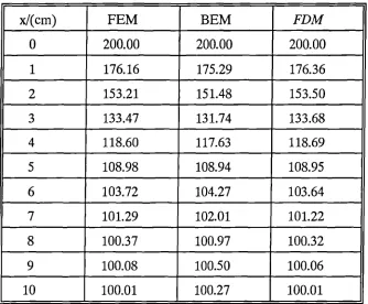
Table 2.1 Temperature distribution of the wall at time t = 10 s
x/(cm) FEM BEM FDM
0 200.00 200.00 200.00
1 176.16 175.29 176.36
2 153.21 151.48 153.50
3 133.47 131.74 133.68
4 118.60 117.63 118.69
5 108.98 108.94 108.95
6 103.72 104.27 103.64
7 101.29 102.01 101.22
8 100.37 100.97 100.32
9 100.08 100.50 100.06
10 100.01 100.27 100.01
2.3 Unexposed Side Heat Transfer Coefficient
In a general case, an insulating panel has an exposed side subjected to fire and an unexposed side losing heat to an ambient environment. Radiation and convection heat exchanges take place on both sides.
k.
h(T)---- c —a-(G Pr
H rH r
(2.15) surface. When the motion of the fluid is induced by buoyancy forces, such as a hot panel in air, and where a change of density of air near the panel occurs due to temperature increases, the mode of heat transfer is called free (or natural)
convection. When the motion of the fluid is externally induced, as with flowing water in a pipe, which will be considered in next chapter, then although a small amount of free convection may be present, the mode is called forced convection. Since in standard test condition, only free convection is encountered on the unexposed face, the calculation of its heat transfer coefficient is presented here.
For natural convection adjacent to a heated vertical or horizontal panel, the following empirical formula applies [2.4]:
where for a vertical panel
c = 0.59 and n = 0.25 for 104 < G,.HP,. <109 ; c = 0.10 and n = 0.33 for 109 < Gail', <i013. kair is the conductivity of air which depends
on temperature: t
H is the height of vertical panel;
kair = -1.56x10 -8T2 +7.43x10 -5T+ 0.023 (2.16)
CHAPTER 2 FDM of a Panel 20
gH3(T-T.)
G - rit (2.17)
v2Tb
where
g is the acceleration due to gravity, 9.8m1s2;
Tb = (T T)12, is the average boundary layer absolute temperature;
v is the kinematic viscosity of air:
V = 6.75x10 -6T2 + 9.55x10⁻³T+1.29 (2.18)
Pr is the Prandtl number of air which approximately equals 0.7.
For the upper surface of a heated horizontal panel
c = 0.54 and n = 0.25 for 105< Grip, <2x10⁷; c = 0.15 and n = 0.33 for 2x10 7 < Gri,Pr <1011.
In the above equation, the characteristic length L is defined as L = A/P, where A is the surface area and P is the perimeter of panel.
When the heat transfer coefficient is known, the boundary condition (2.5) can be applied to the unexposed side. The geometrical factor ( = 1.0 in most cases) and the emissivity of the surface should also be determined.
2.4 Fire Boundary Conditions
Conventionally, fire can be classified as a 'Cellulosic' or 'Hydrocarbon' fire depending on the type of fuel. The standard cellulosic fire test was developed during the early part of the twentieth century and simulated the type of fire which may be experienced in commercial, residential and general industrial construction, while the fire which may occur in the petrochemical industry is appreciably different. In the latter, the fuel is liquid or gaseous in nature. On the other hand, the cellulosic type of fire is characteristic of a fire fuelled by solid combustible materials which is generally in a contained space with limited air movement. Specifiers in the hydrocarbon processing industry have long recognised that the standard cellulosic fire test is less than effective in predicting the performance of fire resistant materials in large scale hydrocarbon-fuelled fires. Nevertheless, cellulosic fires should not be excluded offshore as cellulosic materials are not insignificant, eg, within an accommodation module.
CHAPTER 2 FDM of a Panel 22
in petrochemical industry may include:
. Jet fire: when a stream of fluids burns with some
significant momentum
• Pool fire: when a spill of liquid fuel burns
. Running fire: a fire from a burning liquid fuel which
flows by gravity over surfaces.
Fireball or BLEVE: expanding buoyant ball of flaming gas or a Boiling Liquid Expanding Vapour Explosion caused by a catastrophic failure of a pressure vessel containing liquid or gaseous fuel.
The duration of these different fire types can vary from seconds to days.
The standard fire has been adopted to unify test procedures and to enable materials and construction elements to be compared and classified, although the temperature development described by the currently standard time-temperature curve does not necessarily agree with the temperature development experienced in a real fire.
Currently, there are two basic types of time-temperature curve according to BS476 and AMD 6487[1.1]:
1. Cellulosic time-temperature curve:
Hydrocarbon Curve
\
Cellulosic Curve
2. Hydrocarbon time-temperature curve: T = 1100[ 1 - 0.345 EXP(-0.167 t)
- 0.204 EXP(-1.417 t) - 0.471 EXP(-15.833 t) ] where
(2.20)
T is the mean furnace temperature in (°C);
t is the time (in min) up to a maximum of 360 min.
The graphs of both curves are shown in Fig.2.1. During the first 170 minutes, the defined hydrocarbon curve has a steeper rise and a higher fire temperature. After 170 minutes, although the duration of most tests usually does not last so long, the temperature given by cellulosic curve is higher than that given by the
Temperature (Deg C)
1 i 1 i I I 1 1 1 III
20 40 60 80 100 120 140 160 180 200 220 240 260
Time In mins
Fig.2.1 The Standard Cellulosic and Hydrocarbon Fire Test Curves 11.11 1400
1200
1000
800
600
400
200
CHAPTER 2 FDM of a Panel 24
The expression (2.20) for the representative hydrocarbon fire test, notwithstanding that it is not yet fully accepted by industry, is the most widely recognized curve of this type.
The level of total heat flux could range from 35 KW/m 2 to 400 KW/m2 under standard tests. Whilst a lot of researches have ignored the convective heat transfer because the radiative heat flux is the dominant component of total heat flux, it is not considered that this is a universally correct approach. For engulfed conditions this may be a reasonable assumption. However, outside the fire, the level of radiation drops away and the assumption becomes less valid. The assumption is also less valid for surfaces that are highly reflective. As the magnitude of the received radiation lowers, then the significance of convection increases and convection may make a considerable difference to the fire endurance of the element.
The heat transfer into a construction on the exposed side depends not only on the temperature of the gas and flames but also on the heat transmission characteristics of both the heating environment and the surface which is receiving heat. The heat transfer and gas temperatures vary strongly during fire exposure. As the phenomena associated with heat transfer in the turbulent environment of a fire are difficult to model exactly, the following alternative schemes are suggested:
condition (2.4) in numerical modelling. This excludes the uncertainties with regard to the parameters describing the heat transmission from the furnace to the specimens. In the experimental validations of this research, this method is used first to examine the numerical model. Secondly, it can also be used to validate the heat transfer parameters (see following ii).
ii). Heat transfer parameters: although the exact modelling of the heat transfer from fire to specimen is extremely difficult, eventual consideration should be given to the possibility of including the appropriate heat transfer parameters to predict the heat transfer rate from the fire to the specimen. The heat transfer rate from the fire compartment to the panel could be described as a boundary condition using equation (2.5). Here T., should be assumed to be the mean furnace temperature, and E represents the resultant emissivity. The resultant emissivity could be calculated approximately with the equation for radiation between two infinitely large parallel planes[2.4], so that:
E- 1
11E1+11E5- 1
where
Ef is the emissivity of gases, flames and walls in furnace;
Es is the emissivity of surface material of specimen.
(2.21)
CHAPTER 2 FDM of a Panel 26
for the furnaces used in the tests has not been performed, an estimate is made which is based on an educated assumption and a series of calculations. Usually the both the emissivities of the furnace and the heat transfer coefficient are assumed to be constants[2.5]. A considerable error was encountered if this assumption was adopted for the gas-fired furnaces. It was found that the both emissivities of furnace and the heat transfer coefficient should be high at the starting stage, and that they then declined as the temperature increased. The declining trend of Ef is consistent with the research results on the emissivity of gas[2.6], insulating brick[2.7] and ceramic fibre linings[2.8]. For the convective heat transfer coefficient, the reason for the decline is that, at the starting stage of a test, the temperature of the furnace is increased very quickly so that the extent of fire turbulence is high at first.
In the environment of the furnace used for Cellulosic fire test, it is assumed that .E1 = 0.9 at the beginning of the testing and then linearly declines to Ef = 0.15.
The average of both values is close to the conventional value of 0.5. The -. , heat transfer coefficient is h1 = 60 WIm 2 °C at beginning of the test and this decreases to h2 = 2 WIm2 °C at 1000°C. The numerical results based on these
parameters give a good correlation with experimental results(see Chapter 6).
For hydrocarbon fires, similar results can be obtained. The slight difference is that at initial stage, the heat transfer coefficient should be higher than with a cellulosic fire.
CHAPTER
3
Finite Difference Modelling of a Pipe
Another extensively used component of construction in onshore and offshore constructions is pipework. A cylindrical polar coordinate model is needed for the heat transfer analysis of pipes under hostile thermal impact. Usually the heat loading is around the outside of the pipe and the following analysis is based on this assumption. Only a slight modification is needed to deal with the reverse case, i.e., heat loading from the inside of a pipe, such as the chimney problem.
3.1 1-D Explicit Formulation of FDM for a Multi-layer Pipe
Assuming that the pipe is subject to a uniform heating condition and that the heat transfer occurs only in the radial direction of the pipe, the general one dimensional heat conduction equation can be written as:
pC —aT = —1-5(07)r—OT) in Rirs1?2, for t>0 P at r ar ar
28 where
r is the polar coordinate.
kr is the thermal conductivity in the radial direction.
RpR2 are the inside and outside radii respectively.
The boundary and initial conditions are similar to equations (2.4), (2.5) and (2.6). The boundary condition on r=Ri or r=R2 for t>0, is either:
T = Tg(t) (3.2)
where T
g (t) is the known temperature given on the inside boundary or outside boundary; Or, if the boundary is losing heat to or gaining heat from an ambient temperature condition:
c7T
k(7)— = h(7)(To.-7) + FEaHT.,+273)4 -(T+273)4] (3.3)
an
The initial boundary condition is:
T = To(r) for t = 0 in R1 srsR2 (3.4)
where To is the known initial temperature distribution.
of sandwich design in pipelines include enhanced insulation capability, double integrity containment and leak or failure protection. The problem requires four different types of FDE to be derived:
a) the interior nodes within one material layer; b) the interface nodes between two material layers; c) the external boundary node;
d) the internal boundary node.
(a) For an interior node m within one layer:
Ti #1 = Ti +
1-* 2 "1+
m Or2
+ km _i,m(r„,-1)(Tni,
The evaluation of the conductivity k„,_ /,„, or km+im is same as in equation(2.9).
The Fourier number is
[k
mn" i (r /Or ÷0.5 ) + -1,m(r „, /Or -0.5)7 dt
F- '
2PCpTmÔT
(3.5)
(3.6)
CHAPTER 3 FDM of a Pipe 30
T.1+1 = 7'1+ At
p Spi (rni -Ori/4)6r 1/2 +p2Cp2(r.+6r2/4)6r2 /2 .1-k"+1
(r„, /6r2 +0.5)(Tm1 #1-T,;)+1c._4.(r„, gr1 -0.5)(Tml _1-7;)]
The Fourier number is now
F =min+i(rm /6r2 +0.5) +km _i,m(rm /Or, -0.5) At ° p Spi (rm -Or /4)Sr + p 2Cp2(r.+6r2 /4)6r2
where subscripts 1,2 indicate the two materials respectively.
(c) For the outside boundary node m:
Tmi #1 Tin + At [km_im(r. / Or -0.5)(T.1 pC p(r.-6r/4) 6r/2. '
(3.7)
(3.8)
(3.9)
h(T)r.(Tfire -t) + FE ard(Tfire +273) 4 -(t +273)4)]
where Tfire is the furnace temperature. The Fourier number is
(
m rm /Or -0.5) +hr m +FE arm(Tm +273)4/Tm] At
F - nim
pCp(r.-6r/4)Sr
(3.10)
CHAPTER 3 FDM of a Pipe 31
calculation.
(d) For the inside surface node 1:
Tii#1 = + 2At fki 2 (ri + 0.5 Or)(T2i -7'1) +hr Or(Ta -Td] (3.11)
pCp(ri +0.2. 5 Or)(Or)2
where is inside heat transfer coefficient Ta is the temperature of inner flow
3.2 2-D Explicit Formulation of FDM for a Multi-layer Pipe
When the heat loading is no longer uniform along the circumferential direction of a pipe, the problem becomes two dimensional. In this case, the general two-dimensional heat conduction equation can be written as:
r, 87' 1 8 ,
n r,,,, 8T, 1 8 „e,,„ OT
-- i , ( A 1-1
-a
r r 2 09 80(3.12)
in R1 r R 2 , 0 0 27r
where
CHAPTER 3 FDM of a Pipe 32
kr is the thermal conductivity in the radial direction;
ke is the thermal conductivity in the circumferential direction;
R1 ,R2 are the inside and outside radii respectively.
The boundary and initial conditions are similar to equations (3.2),(3.3) and (3.4). There are four different types of FDE to be derived as well:
a) the interior nodes within one material layer; b) the interface nodes between two material layers; c) the external boundary nodes;
d) the internal boundary nodes.
(a) For the interior nodes within one material layer:
T' = T. + At 40(ri +0.5)(Ti+m-Tin)
41
pC
g
r.drA0 Ar
P
ri LIT
+ A 0(— k°• ..;„_1;, " dr "" "'ride
(Tij-1-7i)÷ ki.
e
w q) Ar
rede(Tii+l-Tu)]
where a prime ' denotes the temperature at next time step.
(b) For the interface nodes between two material layers
u = T1, + 2 At pnC pn(r L -0.25 Ar ft)Ar n + pn+IC;+1
r.
(ri +0.25 Ar n+1)Ar"1] A 0) -1 f Ic(27.1) .A 6( g +0.5)(T. +1 —Tij) Arn+1
r.
+ kr'n A 0(-. —0.5)(T. —7)1-1j AT n
• an Ar n +k"+I Arn+jiTij J÷I) i,Cij +1) • 1
+ (Ic e'n Ar n +ic on +1 A n#1 4u-4D r ) ( Tii -1 —7; ) ]
2ri A 0
2riA 0
(3.14)
where the superscripts n,n+1 indicate materials.
(c) For nodes on the inside surface:
T' . = T 2 At
kzI
0(1-:fe ' r +0.5) •1J pC p(r +0.25 Ar) A r A 6 ' (T2j-7i) + kie(_ij)
2r A
A
r 0(7,
11. _7 I •
ke J-) 4_ 1,(ij +1) 1 Ar
(Ti . #1 -7.1 ) + r 1 7A 01 2r I A 6 '1
(3.15)
where 7 is the unit net heat flux due to radiation and convection. The evaluation of
7
will be presented in section 3.3.e heat capacity of air can be neglected due to the small mass of air
I II
with air,
CHAPTER 3 TDM of a Pipe 34
2A1 r ,
ru =
pC Jr.-02511r) kt(r1414141A 9( r —.au/
keoj„,i) A r -Tij)
2ir
ka4-1.42reir
4j-1 2riA 0 4+1hifirgitifTfre-Td FaerKAOffTfire -1-273)4-(T +273)4 )1
(3.16)
33 Internal Heat Exchange
For one-dimensional analysis, if the inside of pipe is empty, eg, the pipe is filled
inside. If the pope is filled with flowing water, forced convective heat dissipation is encoomtered. For a flow inside a circular tube, the rate of heat transfer depends on e type of flow, le, laminar or turbulent flow. When the flow through ii ye pipe is stre mlined and in consequence little mixing takes place, the heat transfer is relatnely poor. When the flow becomes turbulent and there is
very rapid mixing action, much higher convection rates then take place.
The Reynolds number, defined as Re = un, D v is used as a criterion for defining
e heat capacity of air can be neglected due to the small mass of air
I
with air,
Zit
-14.11
= T - kr .11,A -0.5)(Ti 4-Ti.j)
pC'p(r.-0.25 Ar) Ar A 0 141 - Ar
k Ar .) Ar (T. .
4'4 ZriAr (14.1) 2r ill 0 4+1
(3.16)
h(T)rgiO(Tfre-Tv) FacriA Oarfire +273)4 -(Tij+273)411
33 Internal Beat Exchange
For one-dimensional analysis, if the inside of pipe is empty, eg, the pipe is filled
inside. If the pipe is in ied with flowing water, forced convective heat dissipation
is encountered_ For a flow inside a circular tube, the rate of heat transfer depends on e type of flow, ie, laminar or turbulent flow. When the flow through , oe pipe is streamlined and in consequence little mixing takes place, the heat transfer is relatively poor. When the flow becomes turbulent and there is very rapid mixing action, much higher convection rates then take place.
The Reynolds number, defined as Re = un, D v is used as a criterion for defining
CHAPTER 3 FDM of a Pipe 35
of the fluid. The range of Re value in the transition stage is around 2000 Re < 4000. Since in most practical cases the values of Re are greater than 4000, turbulent flow inside the pipe is assumed. The empirical formula which was proposed by Nusselt is employed to calculate the internal heat transfer coefficient h(T)[ 2. 4 ] :
h(7) = 0.036ReasPrifi(D/4"551- for 10<—L<400 D
(3.17)
where
L is the length of the pipe;
D is the inside diameter of the pipe;
k is the conductivity of the fluid;
Pr is the Prandfl number of the fluid.
The fluid properties are evaluated at the bulk mean fluid temperature. A typical illustration of the influence of fluid speed on the inside temperature rise in a GRP
pipe under the standard hydrocarbon fire test is shown in Fig.3.1.
If the pipe is filled with stagnant water, the problem will be more complicated because a mixture of conduction and convection occurs. At low temperature, the heat transfer through the water may be considered to be by conduction only, while, as the water temperature increases rapidly in a fire environment, convection will occur.
qc = fi(Ti - T . )7 (3.18)
the different parts of the inside surface should be taken into account. Although many construction components and assemblies enclose voids, no general procedure which may be used to calculate heat exchange by radiation and convection through a void has been available[3.2]. Thus some simplifying assumptions are normally needed. One of these is to consider the conduction and specific heat of the internal air to be negligible. The inside curved surface is replaced by a finite number of discrete straight zones. The convective heat transfer to an enclosure boundary is written as
where
13,y are the convection factor and convection power; Ti is the surface temperature of the zones;
Tair is the fictitious inner air temperature.
The air temperature is assumed to be uniform over the inside of the void and there is presumed to be no flow of air either in or out of the void. The total heat transfer to the air from the enclosure surfaces must be zero at any given time in order to conserve the energy. The total heat transfer to the enclosed air is
N
=' qc, Ai = 0
i 4
where
N is the number of zones;
Cid is the heat flux per unit area;
CHAPTER 3 FDM of a Pipe 37
is the area of zone i.
If all of the temperatures T
i
are known, Tair
can readily be computed by iteration and the local heat transfer to zone i can be calculated.Regarding radiation, only diffuse-grey surfaces are considered. This means that the directional spectral emissivity and absorptivity do not depend on either angle or wavelength, but only on surface temperature. Although most materials are not truly diffuse-grey, this assumption simplifies enclosure radiation theory and is often made. The inside surface of the pipe is divided into a number of zones. The temperature and heat flux of each zone are assumed to be uniform. The Hottel's crossed-string method[3.3] may then be employed to calculate view factors for the two-dimensional configuration. Radiation heat flow and absolute surface temperature for an enclosure with N zones can be related by the following expression[3.4]
N
-e. 11
1
,
NZ(- 41 - 1 =
E(Fki -
(5k) cal=1
5
eI A j •=1(3.20)
140 120 100 80 60 40 20 0
Temperature (Deg C)
o 3 6 9 12 15
Time in mins
Fig.3.1 Inside Surface Temperature Rise in a GRP Pipe (5mm) with Flowing Water
39
CHAPTER
4
Models for Polymeric Composites
4.1 Introduction
The use of fibre reinforced polymer composites, and in particular Glass-fibre Reinforced Plastics (GRP), is increasing now owing to their inherent advantages in material characteristics, such as good corrosion resistance, low weight and cost, long service life and low thermal conductivity, typically 1/10Dof steel. However, because plastic materials are organic in nature and are inherently combustible, one of the key problems which needs to be overcome before they are accepted for wider use relates to the need for improved understanding and quantitative evaluation of their behaviour in fire. Accurate knowledge of the thermal response of GRP at high temperature is therefore essential for the reliable and economical design of composite structures in hostile fire environments such as may be encountered on offshore oil platforms.
temperature reaches a certain level (usually around 200-300°C) beyond which decomposition begins to occur and the resin components degrade to form gaseous products at a measurable rate. These gaseous products, initially trapped within the composite matrix owing to its low permeability, attain very high internal pressures and induce the solid matrix to expand. Once the decomposition process begins, the thermal behaviour of the material is altered by the chemical reactions, thermochemical expansion and variable thermal and transport properties. Meanwhile, a considerable amount energy will be required in order to break the constituent chemical bonds. As thermal decomposition proceeds, a residual char layer then builds up as the pyrolysis front moves further into the virgin solid. An advantage of thermosetting resins (which are generally used in GRP) is that usually they do not melt when heated owing to their highly cross-linked chemical structures. Initially, the char layer provides an increasing thermal resistance between the exposed surface and the pyrolysis front as a consequence of its low thermal conductivity and because it can only be ignited with difficulty at normal oxygen concentrations. This is the one reason why GRP can provide a useful fire barrier performance, despite it being an organic material. However, after this initial phase, at a certain stage in the heating process, a network of fissures develops in the carbonaceous char layer due to the release of high pressure gasses. At very high temperature, the char is then gradually oxidized and erodes away. Then the heat resistance of char layer will be totally lost and the glass-fibre remains alone. Under extremely strong heat flux, such as is experienced in a hydrocarbon fire, even the woven roving glass plies will crimp and eventually crumble away.
t"5
CHAPTER 4 Models for Polymeric Composites 41
is
aerospace industry, which,usually associated with rocket nozzles or missile reentry situations. Their major concern is the total energy which must be absorbed into the surface body rather than a heat transfer rate. Another consideration is that in their situation, a portion of surface body exposed to the hot, high speed fluid flow is allowed to melt and rapidly blow away.
Over the past 50 years, several analytical models have been proposed which consider heat transfer in decomposing materials [4.1 to 4.9]. All of these procedures were basically a transient heat conduction calculation in conjunction with the effect of decomposition. The differences existed in their assumptions, approximations, the phenomena included and the property data used. Although most of these studies were concentrated on wood, they provided a theoretical basis for further investigation of the fire performance of other combustible materials.
There are two basic ways to tackle the decomposition of material implicit and explicit approaches. The implicit methods[4.4,4.9] include the effects of decomposition by artificially increasing the specific heat for the temperature range in which pyrolysis occurs. The author does not think that this is very appropriate for such a complex problem. The comprehensive explicit methods[4.3,4.6,4.8] model the decomposition as an exponential kinetic rate equation. The conservation of mass and heat of reaction are therefore included. The diffusion of volatiles is also considered. It is believed that this is a better approach.
composite materials together with an experimental verification. Most of the essential processes relating to the temperature development in the process of decomposition were included in the model. But, probably because of the test assembly used, the fact that only a relatively low constant heat flux was imposed, and due to the particular material used in their test, the profile of measured rate of increase of temperature did not display as much variation as we have observed in standard fire testing of GRP panels.
In this study, the solution of a more realistic problem is attempted, namely that of a glass-fibre reinforced plastic panel and pipe exposed to the time-temperature regime of a standard fire test. For the associated tests, the furnace temperature was controlled by computer to follow the standard BS476 cellulosic fire or hydrocarbon time-temperature curve 1.11.
The fire tests revealed that if the empty GRP pipes were exposed directly to a hydrocarbon fire, they can only survive for a few minutes. Therefore it is necessary to add additional protection to the plain GRP pipes. One method is to use a polymer based flame-retardant intumescent coating.
CHAPTER 4 Models for Polymeric Composites 43
char then forms and this is expanded by the spumific agent which provides a good insulating blanket due to its low thermal conductivity. These reactions combine to make intumescent coatings into a most efficient fireproofing material although the labour involved and cost are relatively high.
To date, only a few mathematical models have been based on the fundamental chemical or physical processes occurring in a complex intumescent coating system such as heat transfer, kinetics, and swelling[4.10 to 14]. The various physical processes were considered in mass and energy control volumes. Expansion has been accounted for by assuming it to be a function of mass loss.
the
With the combination of„above models and the treatment which was originally developed by J.B.Henderson and T.E.Wiecek[4.8] to predict the thermal response of a polymer composite simultaneously undergoing decomposition and thermochemical expansion, an analysis of the heat transfer problem associated with intumescent coatings under hydrocarbon fire is carried out in this paper. The accuracy of the model was evaluated by comparing predicted and experimental temperature distributions in the intumescent coated GRP pipes.
4.2. Model for WR Polyester Laminate
1
1 I I I I I I
characteristics, unsaturated polyesters are the most extensively used type of thermosetting resin. Woven Roving (WR) cloth is a popular fabric to produce high directional strength characteristics. Bidirectional roving cloth laminate, which was used in the present study, has high strength properties in two directions at right angles to each other. The WR glass/polyester laminates were made using a hand lay-up technique with a ply angle of zero. The thin
i i il 4. r eruc t ›) )
thermocouples (K type) were embedded insiore the central area at different locations to measure the temperature profile history across the cross-section of the laminates (Fig.4.1).
6 5 4321
Fig.4.1 The layout of laminate and the location of thermocouples
CHAPTER 4 Models for Polymeric Composites 45
most of the material parameters involved. The most promising approach is to form a mathematically viable but relatively simple model which can capture the main features of the pyrolysis process and the consequent heat transfer behaviour. Therefore, several idealizations are made:
a). The GRP material is assumed to be homogeneous and the transport of heat and mass is perpendicular to the face of panel so that the problem is assumed to be one dimensional.
b). The rate of decomposition is assumed to conform to a mean reaction which is described by a single first-order Arrhenius function.
c). There is thermal equilibrium between the decomposition gases and the solid material and there is no accumulation of these volatile gases in the solid material.
d). The feedback of heat released by the flame of the combustible volatile back to the panel in a small scale furnace test is neglected owing to its relatively small contribution compared with the enormous heat flux created by the furnace. However, it is anticipated that in large or full scale fire tests, or in the case of sustained combustion after removal of the heat source, its contribution may not be ignored.
decomposition expresses a balance between the transient energy accumulation rate, with the sum of the rates of conduction, pyrolysed convection, and the energy sink due to decomposition[4.6]
8 Op
-L3 (ph) =—(k—)81' -—(m0 , g hg) -Q
a
a
& dc c7xwhere
p is density (kg/m3)
h is the enthalpy (J/kg) of .50 icLi t is time (s)
T is the temperature (°C)
k is the thermal conductivity (W/m°C) x is the spatial variable (m)
hg is the enthalpy of gas(J/kg) m ' g is the mass flux of gas (kg/m2-s) Q is the heat of decomposition (J/kg)
The specific enthalpies of the solid and volatile are
h
= rTo ToCpdT , hg = fr_ CpgdT (4.2)
(4.1)
where T. is the ambient reference temperature.
CHAPTER 4 Models for Polymeric Composites 47
in GRP is assumed to conform to a mean reaction which is described by a single first-order Arrhenius function
dp,
dt - -A prexp(-EA/R7)
where p r is the instantaneous density of partially pyrolysed resin, E A is the activation energy (J/mol), R is the gas constant (8.314J/K.mol) and T is the temperature (K). The constant A is known as the pre-exponential factor and has unit of s -1 . The relationship between the p and p r is:
p = prv + p g (1 -v) (4.4)
where p g is the density of glass-fibre and v is the volume fraction of glass-fibre. The glass-fibre is assumed to be intact in the time zone of interest under fire.
Here, the resin pyrolysis is assumed to be a continuous process until it is totally consumed. Some investigators have included the final density of the char in the expression (4.3). This will cause two problems in practical application. One is that the precise definition of the final char status is difficult to define. Another point is that yet another expression for char pyrolysis will be then required if it commences its final breakdown in the time zone of interest. Although much research has been carried out into the thermal decomposition of polymers, in view of the chemical complexity involved, combined with problems of interpreting data from a variety of sources and experimental assemblies, the available data is still very limited and not in a form suitable for warranting improvements to the
am'
g op (4.5)
above relatively simple treatment.
Another facet which shows the complexity of the problem is the determination of the heat of decomposition (sometimes called the heat of pyrolysis or heat of reaction). It was reported that its value for wood, for instance, varies greatly[4.15]; and that not only the magnitude but the actual sign of this property has been the subject of debate for many years[4.16,4.17]. We prefer the allegation which declares that the decomposition process itself is endothermic overall. The exothermicity often noticed in the burning of wood and plastics is a result of the reaction between the outflowing volatiles and oxygen. A minor exothermic reaction might happen within the extremely complicated competing reactions, or a local exothermic phenomenon appears due to the change of specific heat. However, in most circumstances, the endothermic reaction is believed to be dominant in the decomposing process for polymeric materials.
If the accumulation of gases and the effect of expansion on density change are ignored, the conservation of mass may be written as:
and the mass flux, m , g, at any spatial location and time can be calculated by integration of Equation (4.5).
CHAPTER 4 Models for Polymeric Composites 49
OT 82T c aT -!9
. 12(Q, +h -hg) pC = k-4-2,c2 m g pg
where
is the specific heat of material (J/kg°C); is the specific heat of gas (J/kg°C). Pg
Equations (4.3), (4.5) and (4.6) form a set of non-linear partial differential equations which may be solved simultaneously for p, m ' g and T respectively.
The boundary conditions on the exposed and unexposed surfaces of a panel could be either a prescribed temperature or a radiation and convection boundary condition. To exclude the uncertainties of the heat transmission rate from the fire to the samples under test, the measured temperature can be used as the boundary condition at the exposed side. On the unexposed side, equation (2.5) is again applied.
The initial conditions for 0 x L at t = 0 are
=Ti; p = po ; m'g =0. (4.7)
where
Ti is the initial temperature (°C); p 0 is the initial density (kg/m3).
(4.6)
6 5 4.4' 2,3' 2 1
1
1 i
1 1 II 1 1 1 1 I 1 1 1 I II I I I I I I
1 I II I I I I I I 1 I I I I I I I 1 1 I II I I I I I I /I 11111111/
1 1 1 1 1 1 1 i
1 1 1 1 1 .W
in
apply to the epoxy and vinyl ester systems. However, for phenolic resin laminates, a more complex behaviour was observed. This requires a special treatment which will be discussed in the next section.
4.3 Special Treatment for WR Phenolic Laminate
Phenolic (phenol-formaldehyde) resins, whose development was once superseded by that of polyesters and epoxies, have experienced a recent recovery in popularity which is mainly attributable to their good fire resistance and low smoke emission (about 10% that of polyester-based GRP).
The test samples of woven roving glass/phenolic laminate were made in a similar manner to the WR polyester laminates as shown in Fig.4.2.
1200
Hydrocarbon Curve4 Ave' Furnace Tame
Cold Face Tema.. 1000
800
600
400
200
CHAPTER 4 Models for Polymeric Composites 51
The resin which was used for fire tests was Cellobond FRP liquid phenolic resole resin J2027L which was supplied by BP Chemicals. According to the supplier, this material has a high degree of fire resistance and excellent high temperature mechanical properties with minimal smoke or toxic fume emission. In order to
\Neva
obtain more information, there _ two embedded thermocouples within the layers at the same nominal depth below the surface. After curing, the flat samples were clamped in a vertical position over an opening cut into the door of the fire testing furnace and were exposed to ambient air on the other face. The size of each panel was 380x380 mm 2 with an area of 250x250 mm2 exposed within the furnace. A typical hydrocarbon fire test result of WR phenolic laminate is shown in Fig.4.3.
Temperature (C)
5 10 15 20 25 30 35 40 45
Time in mins
A first impression of Fig.4.3 suggests that the temperature response inside the phenolic laminate was quite erratic. In the initial stages of the test, the temperature rose at a moderate rate. Then, at about 200°C, there was a sudden drop of temperature at most locations. After this sudden drop, the temperature at each location concerned increased rapidly again. It was found that this unusual behaviour is due to the delamination of the laminate.
Consider, for example, the output of measured temperature given by two thermocouples at position 3 (see Figs.4.2 and 4.3, where 3 and 3' refer to two different thermocouples in the same layer). Before the temperature reaches 200°C, both thermocouples indicated almost identical temperature values. Then, at 200°C, the reading of one thermocouple suddenly dropped to 80°C. This indicates that the cooler air was drawn into the interstice when a delamination abruptly occurred. After delamination, the outcome of measured temperature will be strongly dependent on the location of the thermocouple which introduces a random element into the measurements. As illustrated by Fig.4.4, if the thermocouple is attached to the surface B, its reading will be high. If the thermocouple is attached to the surface B', its reading will be low. Evidently, if the thermocouple is remote from the region of delamination, an intermediate reading will be obtained. Furthermore, in volatile turbulence, the reading given by a thermocouple in the region of a delamination is unlikely to remain completely stable. This is illustrated by curve 4' in Fig.4.3.
CHAPTER 4 Models for Polymeric Composites 53
by the vaporization of intrinsic water (by-product of polymerisation[4.18]) in the resin over 100°C. The water vapour, initially trapped within the composite matrix owing to its low permeability, attains very high internal pressures as heating continues. At about 200°C, a sudden release of high pressure tears the laminate. A subsequent examination of the tested sample also reveals the appearance of deaminations.
B A
Fig.4.4 Heat transmission through a delaminated surface
temperature at that point declines. It is clear that the heat transfer by conduction is disturbed by delamination. This is one of reasons why the cold face temperature of WR phenolic laminate can remain at a low and fluctuating level for quite a long time. Another reason is the energy sink caused by the decomposition of the resin as described for polyester resin in the previous section.
The fundamental equations for this problem are the same as those formulated in section 4.2. However, a particular heat transmission equation will now be established for the delaminated interfaces.
As shown in Fig.4.4, it is assumed that the layer AB is detached from the main body of the laminate. Then an additional term should be included in the energy conservative equation for points B and B' to take account of the heat transmission by radiation and convection between B and B'. If these are assumed to be on two infinitely large flat surfaces, the equation for the magnitude of heat flow G is
G = Er a I(T B 4-273)4 - (TB/+273)4] + H (TB -TB!) (4.8)
where
Er is the resultant emissivity; H is the heat transfer coefficient.
On the right hand side of equation (4.8), the first term represents the radiation and second term represents convection.
CHAPTER 4 Models for Polymeric Composites 55
of above two parameters are difficult, they are determined by finding a reasonable fit between the model and the observed results. In the final analyses, Er is set as 0.9 and H is given the value 20 WPC. It is found that the radiation energy provides the major component of G.
By introducing this equation, a good agreement between the experimental and computational results was obtained (see chapter 6). It demonstrates that a good explanation has been given for the bewildering outcome of the measured temperature development in WR glass/phenolic laminate in a fire.
4.4 Model to Predict the Thermal Response of GRP Pipes
In the offshore industry, it is necessary to design key components of the installation to withstand the effects of fire. One such component is the fire-water system which supplies a deluge of water in the event of a fire-related emergency. Traditionally, fire-water systems have used steel pipework but there is considerable interest in replacing steel with GRP because of its corrosion resistance and lighter weight[4.19]. In order to prove the viability of GRP dry riser pipes in this context, it is necessary to demonstrate that they can withstand the effect of the fire on the empty pipe until the pipe is full of water and the deluge system is in operation.
analysis. A one-dimensional analytical model for GRP pipes subjected to a vn1 as
prescribed time-temperature history applied by the furnace developed. The vJa.s
explicit finite difference method employed to solve the transient heat conduction equation in polar coordinates. The performance of GRP pipes under fire condition is quite similar to that of GRP laminates. The two possible differences could be
1. Although some blisters may be observed on the inside of the pipe at the final stage of a fire test, wholesale delamination in GRP pipes can not happen because the glass-fibre reinforcement is wound helically into the cylindric shape.
2. The loss of heat from the cold face, i.e., the inside of pipe, is restricted in the empty pipe. This means that the temperature increase in the pipe will be more rapid.
The fundamental assumptions and principles described in above sections are still applicable for pipe problems. The only thing that is required is to recast the equations in a polar coordinate system. The transport of heat and mass is assumed to be only in the radial direction of the cross-section.