© 2016, IRJET ISO 9001:2008 Certified Journal Page 2611
STATIC AND DYNAMIC ANALYSIS OF REGULAR AND IRREGULAR SHAPE
BUILDING WITH OR WITHOUT SHEARWALL
Vidyashree S.R
1, Dr. M.D Vijayananda
2, Er. Kirankumar K.L
31
Post graduate student in structural engineering, ,BIET College, Davangere,577004 India
2
Professor and Co-ordinator, PG program M.tech structural engineering, BIET college, Davangere
3
Structural Design engineer, Chetana Engg. Services Pvt. Ltd Bengaluru,560052 India
---***---Abstract - Construction of High-rise buildings is
common in the present days due the availability of limited space, growth of population and high cost of lands. Hence to safeguard the construction, the buildings to be constructed must be designed in such a way that it should withstand both gravity loads as well as lateral loads (earthquake, wind and blast load). The present study is done by providing the lift core shear wall to the RCC building to gain the necessary stability, strength and also the stiffness to resist the loads coming horizontally i.e., Earthquake load. Here both regular and irregular shaped building is analysed by providing with or without shear wall. The results are studied for both Equivalent static method (Linear static analysis) and Response spectrum method (Linear dynamic analysis) using ETABS 2015. The proposed building is situated in the seismic Zone V and the results are tabulated for different soil types and the attempt is made to reduce the displacement with the introduction of structural shear wall system. The parameters considered in this study are storey displacement, storey drift and storey shear. The structure is studied under different soil types ( Type I, Type II and Type III) as per IS 1893:2002 In this study the main focus is to determine the importance of presence of lift core shear wall.
Key Words: Seismic Analysis, Framed Structure, Lift core shear wall, Equivalent static method, Response spectrum method
1.INTRODUCTION
Earthquake is a passage of different vibrations from ground. Earthquake is unpredictable and occurs irrespective of time and location and our country has experienced many earthquake resulting in severe damage to structure and loss of life. Hence the design engineers has to design the building in order to make it resistible for damages caused due to effects of seismic actions. These experiences have demonstrated the new developments in building up the resistance towards seismic actions and their execution must be proper to protect against seismic damages. RC frame
building have become common type of construction now-a-days. The performance of frame system alone for the earthquake is not effective and it is not stiff compared to structural wall system. Hence the structural wall system should be adopted to resist the lateral load (seismic load). Thus shear wall is used and it is capable of reducing damages caused by earthquake and cost effective and also also advantageous in reducing the overall deflection. In our considered model the shear wall is continuous without any discontinuity from the base upto full height of the building and rigidly connected and its position is defined according to the building requirements and necessity aspects. Shear wall adds higher stiffness to the building and also adds less weight to the building
.
1.1 Shear wall
Shear are the lateral force resisting system which supports the floor or roof diaphragm which basically transfer lateral force ultimately to the foundation system. The properly designed and constructed shear wall can have proper stiffness and strength for resisting the lateral loads. Now a days it is mandatory for tall structure in severe seismic zone. Shear walls are available in different forms, shapes and usage is based on the architectural point of view and functional point of view in high rise buildings
.
2. OBJECTIVES
1
.To perform the linear static analysis on considered model. 2.To perform the Dynamic analysis(RSM) on considered models3.To examine the effect of shear wall(Lift core wall) locations in considered models.
4.To determine the storey displacements, storey drifts and base shear under earthquake loading.
© 2016, IRJET ISO 9001:2008 Certified Journal Page 2612 different soil types , lift core shear wall system is considered
for regular and irregular plan and comparision is done between bare frame model and the combined shear wall model using ETABS software as per code IS 1893: 2002. The four different models were studied in Zone 5 and results are tabulated for the Base shear, storey displacements and storey drifts.
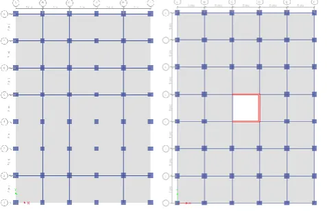
Fig -1: Plan of regular buildings (without shear wall and with lift core shear wall)
[image:2.595.301.503.151.414.2]Fig -2: Plan of irregular buildings (without shear wall and with lift core shear wall)
Table -1: Preliminary Data.
Bottom storey height 4.0 m
Typical storey height 3.0 m
Size of the Column 900mmx900mm
Size of the Beam 200mmx600mm
Slab thickness 125 mm
Shear wall type Lift core shear wall
Shear wall thickness 200 mm
Concrete density 25 kN/m3
Steel grade 500 N/mm2
Floor finish 1.5 kN/m2 (on floor), 2 kN/m2 (on roof)
Table -2:
Model Description.
Model no. Soil type Plan Presence of
shear wall
M1 Type I Regular No
M2 Type II Regular No
M3 Type III Regular No
M4 Type I Regular Yes
M5 Type II Regular Yes
M6 Type III Regular Yes
M7 Type I Irregular No
M8 Type II Irregular No
M9 Type III Irregular No
M10 Type I Irregular Yes
M11 Type II Irregular Yes
M12 Type III Irregular Yes
4. RESULTS AND DISCUSSIONS
Table 3: Equivalent static method
MAX. STOREY DISPLACEMENT(mm)
MODEL NO. EQX EQY SOIL TYPE
M1 113 104
TYPE
I
M4 94 90.6
M7 109 115
M10 93 89.7
M2 154 142.5
TYPE
II
M5 128 123
M8 148 156.4
M11 127.1 122
M3 189 175
TYPE
III
M6 157 151
M9 182.1 192.1
[image:2.595.36.275.195.349.2] [image:2.595.36.280.395.559.2] [image:2.595.35.525.491.782.2]© 2016, IRJET ISO 9001:2008 Certified Journal Page 2613 Table 4: Response spectrum method
MAX. STOREY DISPLACEMENT(mm)
MODEL NO. RX RY SOIL TYPE
M1 77.28 72.46
TYPE I
M4 62.168 50.585
M7 74.84 71.57
M10 61.121 48.7871
M2 110.87 103.64
TYPE II
M5 89.4389 78.934
M8 107.09 110.38
M11 88.1934 76.774
M3 139.76 130.3909
TYPE III
M6 114.2954 104.059
M9 134.747 144.005
M12 112.754 101.545
Table 5: Equivalent static method
Table 6: Response spectrum method
INTER STOREY DRIFT
MODEL NO. RX RY SOIL TYPE
M1 0.00127 0.00122
TYPE I
M4 0.00097 0.0008
M7 0.00122 0.00115
M10 0.00094 0.00075
M2 0.00182 0.00173
TYPE II
M5 0.00139 0.00125
M8 0.00174 0.00177
M11 0.00136 0.00117
M3 0.00229 0.00218
TYPE III
M6 0.00178 0.00164
M9 0.00219 0.00231
M12 0.00173 0.00154
Chart -1: Max. storey displacement , for soil type-I along X-direction(static analysis)
Chart -2: Max. storey displacement , for soil type-I along Y-direction(static analysis)
INTER STOREY DRIFT
MODEL NO. EQX EQY SOIL TYPE
M1 0.00164 0.00153
TYPE
I
M4 0.00137 0.00131
M7 0.00157 0.00164
M10 0.00135 0.00129
M2 0.00223 0.00208
TYPE
II
M5 0.00186 0.00178
M8 0.00213 0.00225
M11 0.00184 0.00175
M3 0.00274 0.00256
TYPE
III
M6 0.00229 0.00218
M9 0.00262 0.00273
© 2016, IRJET ISO 9001:2008 Certified Journal Page 2614 Chart -3: Max. Inter storey drift for soil type-I along
X-direction(static analysis)
Chart -4: Max. Inter storey drift , for soil type-I along Y-direction(static analysis)
Chart -5: Max. storey displacement , for soil type-I along X-direction(Dynamic analysis)
Chart -6: Max. storey displacement , for soil type-I along X-direction(Dynamic analysis)
Chart -7: Max., Inter storey drift for soil type-I along X-direction(Dynamic analysis)
Chart -8: Max. Inter storey drift, for soil type-I along X-direction(Dynamic analysis)
The displacement is reduced upto 15-25% for the models with the lift core shear wall compared to the bare frame model in the both X and Y direction for equivalent static method. There is a 15-17% reduction of inter storey drift for the buildings with lift core shear wall compared to the bare frame model in both X and Y direction in equivalent static method for all the soil types. In the response spectrum method it is observed that the parameters such as storey displacements and storey shear have been minimized compared to equivalent static method. Hence proves to be economical for the construction of high rise buildings
.
© 2016, IRJET ISO 9001:2008 Certified Journal Page 2615 It is observed that the base shear is reduced for the Model 7
and Model 10 compared to Model 1 and Model 4 due to the less mass is considered in irregular plan building.
5. CONCLUSIONS
The following conclusion are drawn based on the observation:
1. The displacement of models in soil type II is reduced by 19-36% when compared to soil type III and the displacement of models in soil type I is reduced by 27-30% compared to soil type II in both the analysis.
2. The storey drift of models in soil type II is reduced by 19-22% when compared to soil type III and the storey drift of models in soil type I is reduced by 27-28% compared to soil type II in both the analysis. Hence the soil type I is safe.
3. Displacement increases as the height of building increases.
4. In response spectrum method the displacement values are least in both X and Y direction compared to equivalent static method.
5. Storey drift for considered models are within the maximum drift permitted acc. to Is 1893:2002 6. Reduction in the inter storey drift have been
observed in frame with lift core shear wall compared to bare frame.
7.
The value of base shear is less for Irregular plan building in comparision with regular due to the less mass considered.8. Shear wall proves to be effective in high rise building.
9.
The results obtained from the equivalent static method is seems to be uneconomical as the lateral displacement is more compared to response spectrum analysis and the dynamic analysis is mandatory for the high rise buildings.REFERENCES
[1].D Mohammed yousuf, P.M. shimpale, “Dynamic Analysis of Reinforced Concrete Building with Plan Irregularities” published in International Journal of Emerging Technology and Advanced Engineering, ISSN 2250-2459, Volume 3, Issue 9, September 2013, pp 110-116
[2].P. P. Chandurkar, Dr. P. S. Pajgade,“Seismic analysis of RCC building with and without shear wall”, International Journal of Modern Engineering Research. Vol. 3, Issue 3, pp. 1805-1810, 2013.
[3].Romy Mohan, C Prabha,“Dynamic analysis of RCC buildings with shear wall”, International Journal of Earth Sciences and Engineering. Vol. 04, No. 06 SPL, October 2011, pp. 659-662, 2011.
[4].Md. Rashedul Kabir, Debasish Sen, Md. Mashfiqul Islam I,” Response of multi-storey regular and irregular buildings of identical weight under static and dynamic loading in context of Bangladesh,” International journal of Civil and Structural Engineering, Volume 5, No 3, February 2015, pp 252-260.
[5].Agarwal P and Shrikhande. M., (2006) “Earthquake resistant Design of Structures’ Prentice-Hall of India Private Limited New Delhi India.
[6].Duggal S. K.(2010), “ Earthquake Resistant Design Structues”. Oxfored University press YMCA library building, Jai Singh road, New Delhi.
[7]. Indian Standard, IS 875(Part 1)-1987, “Code of practice for design loads (other than earthquake) for building and structures” Part 1, Dead loads – unit
weights of building materials and stored materials,
BIS, Manak Bhawan, New Delhi, India .
[8].Indian Standard, IS 875(Part 2)-1987, “Code of practice for design loads (other than earthquake) for
building and structures” Part 2 - Imposed loads, BIS,
Manak Bhawan, New Delhi, India .
[9].Indian Standard, IS 456-2000 “Plain and
Reinforced Concrete-Code of Practice,” BIS, New
Delhi, India.
[10]. Indian Standard IS 1893-2002, “Criteria for earthquake resistant design of structures”, Part
1: General Provisions and Buildings, Fifth Revision,
© 2016, IRJET ISO 9001:2008 Certified Journal Page 2616 Vidyashree S R
Post Graduate student Dept. of Civil engineering BIET College, Davangere
Dr. M D Vijayananda
Professor and PG Co-ordinator Dept. of Civil engineering BIET College, Davangere
Er. KiranKumar K.L Structural Design Engineer Chetana Engg. Services Pvt. Ltd Bengaluru-560052