© 2016, IRJET | Impact Factor value: 4.45 | ISO 9001:2008 Certified Journal | Page 546
Design, Analysis and Testing of shaft mounted speed reducer for coil
winding machine.
Kate-Deshmukh N.S.
1, Gaikwad M.U.
21
PG Student, Mechanical Engineering Department, DGI FOI, Maharashtra, India
2
Asst. Professor, Mechanical Engineering Department, DGI FOI, Maharashtra, India
---***---Abstract-
The gearbox is a device which is used totransmit the power from one shaft to the other shaft within the required gear ratio. But, most of the times space limitation becomes the major problem of system. Also efficiency of the device is one of the important parameter. The device should have maximum efficiency. The conventional gear box gives us the required power and speed ratio but, they require the larger space for their working. Also they possess large number of parts and become bulky. In some applications, the space limitation is the important factor while designing the device. The aim of this project is to design a shaft mounted speed reducer which requires the less space and gives required speed ratio. The advantage of this project is, it requires less space and gives high efficiency. The maximum efficiency obtained by this speed reducer is 93.28%.
Key Words: Shaft Mounted Speed Reducer, Design,
FEA Analysis.
1. INTRODUCTION
Shaft mounted speed reducer is a device which is used to reduce speed of a machine from input speed to the required speed. In this device an internal external gear arrangement is used for speed reduction. The external gear is engaged with the internal gear but the external gear is eccentric with the internal gear. Because of such an arrangement reduction of speed can be achieved as per the requirement. We can change output speed by only changing the eccentric distance between the external gear and internal gear. Figure 1 shows construction of shaft mounted speed reducer. The shaft mounted speed reducer is a small cylindrical unit that mounts directly on the drive shaft and transmits power to the driven shaft (not shown)
via a v -belt drive. The centre section on the speed reducer consists of a steel sleeve-A, internal gear –B and pinion-C.
Fig-1: Construction of Shaft mounted speed reduction gear box.[14]
© 2016, IRJET | Impact Factor value: 4.45 | ISO 9001:2008 Certified Journal | Page 547 about axis z-z .A secondary effect of the tendency to rotate
about axis Y_Y is that adequate tension is maintained on the v-belt on sleeve .If it is desired to hold the unit rigid a support arm can be provided from a point on machine to the end plates.
2.
LITERATURE REVIEW:
Govada Tejaswini & G. Chandra Mohan Reddy [1] compared present technologies of the gearbox and the result of their calculated efficiency. From the comparison of various drives, they found that two stage cycloidal drives are having high efficiency (i.e. 92.7%) as compared to the other drives. Padmanabhan S. et al. [2] developed Ant Colony Optimization for a Worm gear drive problem with multiple objectives. Within the various design variables available for a worm and worm wheel design, the power, weight, efficiency and centre distance have been considered as objective functions and bending stress, compressive stress as vital constraints to get an efficient compact and high power transmitting drive. Chiu-Fan Hsieh [3] proposed a new transmission design for an eccentric speed reducer for which the internal and external gear profiles are constructed via a gear mathematical model and stress tested using a system dynamics analysis model. Wan-Sung Lin a et. al. [4] proposed the design of a new two-stage cycloidal speed reducer with tooth modifications. Hong-Sen Yan & Ta-Shi Lai [5] proposed Geometry design of an elementary planetary gear train with cylindrical tooth-profiles. They present a concept of elementary gear trains such that the tooth-profiles of the pinion are cylindrical
M. Chandrasekaran et.al, [6] developed the genetic algorithms for a single speed gear box problem with multiple objectives. David W. Pessen [7] invented a quick release mechanism for self-locking mating worms. This invention is modification of a self-locking mating worm drive. This invention relates to a release mechanism for self-locking mating worms. Bingkui Chen et al. [8] presented a new cycloid drive with double contact lines between one tooth pair. The new conjugated tooth profile has been generated by applying double-enveloping gear theory in cycloid drives. D. Mundo [9] presentedGeometric design of a planetary gear train with non-circular gears. They presented a concept of epicyclical gear train able to generate a variable gear ratio law. Ta-Shi Lai [10] presented Geometric design of roller drives with
cylindrical meshing elements. He presents geometric design procedures to design the roller drives which have cylindrical meshing elements. Joong-Ho Shin, Soon-Man Kwon [11] Proposed on the lobe profile design in a cycloid reducer using instant velocity centre. They proposed a simple and exact approach for the lobe profile design of the cycloid plate gear, which is a main part of the cycloid reducer, by means of the principle of the instant velocity center in the general contact mechanism and the homogeneous coordinate transformation. Daniele Vecchiato [12] proposed Tooth contact analysis of a misaligned isostaticplanetary gear train.
Yii-Wen Hwang, Chiu-Fan Hsieh [13] presented Determination of surface singularities of a cycloidal gear drive with inner meshing
3.
Design of Shaft mounted speed reducer
3.1 Analytical Method:
Design consists of application of scientific principles, technical information and imagination for development of new or improvised machine or mechanism to perform a specific function with maximum economy and efficiency.
Following parts of shaft mounted speed reducer are designed by analytical and numerical method:
1) Input shaft. 2) LH-sleeve.
3) Input timer pulley. 4) RH-sleeve.
5) External gear. 6) Internal gear. 7) Output shaft.
The following formulae’s are used for analytical design:
© 2016, IRJET | Impact Factor value: 4.45 | ISO 9001:2008 Certified Journal | Page 548 Table-1: Results obtained from analytical method
Sr. no.
Name of Part Max. Allowable
Stress
Analytically calculated shear stress
(
1 Input Shaft 144 3.7
2 LH-sleeve 144 0.02
3 Timer pulley 144 0.0176
4 RH-sleeve 144 0.02
5 External gear 144 0.2
6 Internal gear 95 0.018
7 Output shaft 144 3.52
3.2 Numerical Method:
FEM is a numerical method for obtaining approximate numerical solution of problems of engineering and physics by the aid of computer. The finite element method involves modeling the structure using small interconnected elements called as finite elements.
3.2.1 Finite Element Analysis
Different type’s static, dynamic and thermal analyses can be done in ANSYS. This particular gear train model is simple and subjected to torque on various parts. Critical parts such as input shaft, input timer pulley, output shaft, LH and RH sleeve, internal and external gear are analyzed with static boundary conditions for Equivalent stress, and deformation. In numerical method modeling and analysis of all parts of speed reducer is done using software’s. Modeling is done using Creo-3.0 and analysis is done using Ansys 14.5. Second order tetrahedral mesh is used for FE
analysis. Second order tetrahedral element was obvious choice for this simulation as it is best combination of accuracy of result and efforts required to build FE model. Normal uniform regions are meshed with coarse mesh.
3.2.2 Analysis of input shaft
Fig-2: Equivalent stress contour for input shaft
Fig-3: Deformation contour for input shaft
© 2016, IRJET | Impact Factor value: 4.45 | ISO 9001:2008 Certified Journal | Page 549 Fig-4: Equivalent stress contour for LH-Sleeve
Fig-5: Deformation contour for LH-sleeve.
3.2.4 Analysis of Input Timer Pulley
Fig-6: Equivalent stress contour for input timerpulley.
Fig-7: Deformation contour for input timer pulley.
3.2.5 Analysis of RH-Sleeve:
Fig-6: Equivalent stress contour for RH-Sleeve.
Fig-7: Deformation contour for RH-sleeve.
© 2016, IRJET | Impact Factor value: 4.45 | ISO 9001:2008 Certified Journal | Page 550 Fig-8: Equivalent stress contour for external gear.
Fig-9: Deformation Contour for External Gear.
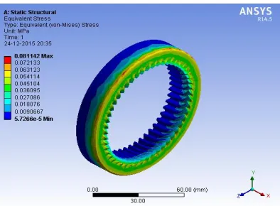
3.2.7 Analysis of Internal Gear:
Fig-10: Equivalent stress contour for internal gear.
Fig-11: Deformation Contour for internal Gear.
3.2.8 Analysis of Output Shaft:
[image:5.612.37.235.235.354.2]Fig-12: Equivalent stress contour for output shaft.
Fig-13: Deformation Contour for internal Gear.
Table no. 2 shows the result of various parts of shaft mounted speed reducer obtained by numerical method using Ansys 14.5.
Table-2: Results obtained from Numerical method Sr.
no .
Name of part Equivalent Stresses
Total Deformation (mm)
1 Input shaft 5.100 0.0023
2 LH-sleeve 0.027 4.00×10⁻⁶
3 Input timer pulley 0.072 2.37×10⁻⁶
4 RH-sleeve 0.066 7.77×10⁻⁶
5 External gear 0.600 8.4 ×10⁻⁶
6 Internal gear 0.080 2.884 ×10⁻⁶
[image:5.612.324.528.324.465.2] [image:5.612.38.235.402.547.2]© 2016, IRJET | Impact Factor value: 4.45 | ISO 9001:2008 Certified Journal | Page 551 3.3 Experimental Method
In experimental method, the model of shaft mounted speed reducer is manufactured using various machines (i.e. Lathe, milling, Centre lathe Milling machine, DRO – Jig Boring machine, Electrical Arc Welding.). The model is tested with the test rig developed i.e. rope brake dynamometer. Following test are conducted during experimentation.
a) Torque Vs. Speed Characteristics b) Power Vs. Speed Characteristics c) Efficiency Vs. Speed Characteristics
[image:6.612.329.545.139.276.2]In order to conduct trial, a dyno-brake pulley cord, weight pan are provided on the output shaft.
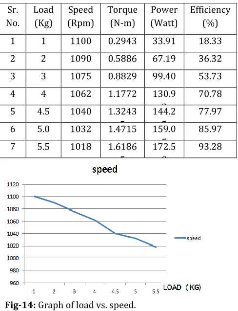
[image:6.612.31.275.350.668.2]Table-3: Results obtained from experimental method
Fig-14: Graph of load vs. speed.
Figure 14 shows the graph of load vs. speed. From the graph it can be observed that speed is inversely
proportional to the load. That is as load increases, the speed reduces by respective amount.
Fig-15: Graph of load vs. speed.
[image:6.612.31.274.352.667.2]Figure 15 shows the graph of load vs. Torque. From the graph it can be observed that torque is directly proportional to the load. That is as load increases, the torque also increases by respective amount.
Fig-16: Graph of load vs. power.
Figure 16 shows the graph of load vs. power. From the graph it can be observed that power is directly proportional to the load. That is as load increases, the power also increases by respective amount.
Sr. No.
Load (Kg)
Speed (Rpm)
Torque (N-m)
Power (Watt)
Efficiency (%)
1 1 1100 0.2943 33.91 18.33
2 2 1090 0.5886 67.19 36.32
3 3 1075 0.8829 99.40 53.73
4 4 1062 1.1772 130.9
3
70.78
5 4.5 1040 1.3243
5
144.2 5
77.97
6 5.0 1032 1.4715 159.0
5
85.97
7 5.5 1018 1.6186
5
172.5 8
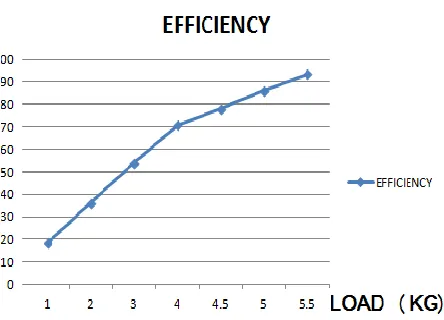
[image:6.612.325.560.353.523.2]© 2016, IRJET | Impact Factor value: 4.45 | ISO 9001:2008 Certified Journal | Page 552 Fig-17: Graph of load vs. efficiency.
Figure 17 shows the graph of load vs. efficiency. From the graph it can be observed that efficiency is directly proportional to the load. That is as load increases, the efficiency also increases by respective amount. The maximum efficiency obtained is 93.28%.
4
RESULT & DISCUSSIONS
Critical parts
[image:7.612.30.297.503.692.2]are validated by analytical calculations as well as FEA i.e. numerical methods. Following table shows comparison of analytical & numerical stress results induced in critical parts of shaft mounted speed reducer.
Table-4: Comparison of analytical & Numerical stress results
Sr.
no. Name of Part
Analytically calculated shear stress ( Equivalent Stresses %Error
1 Input Shaft 5.0750 5.1000 0.49 2 LH-sleeve 0.0244 0.0270 9.63
3 Timer pulley 0.0664 0.0721 7.91 4 RH-sleeve 0.0608 0.0660 7.88 5 External gear 0.5640 0.6000 6.00 6 Internal gear 0.0754 0.0800 5.75 7 Output shaft 5.4013 5.6200 3.89
1. Maximum stress for input shaft calculated by theoretical method and Numerical method are well below the allowable limit. The percentage error between two results is 0.49 %. This error is very small. Also Input shaft shows 2300×10-6mm deformation
which is negligible; hence the input shaft is safe. 2. Maximum stress for LH- Sleeve calculated by
theoretical method and Von-mises stress are well below the allowable limit. The percentage error between two results is 9.63 % which is considerable. But this error is less than 10%, so it can be neglected. Both the values of stresses are well below the allowable stress; also the LH sleeve shows 4.00×10 -6mm deformation which is very negligible. Hence the
LH sleeve is safe.
3. Maximum stress for Timer pulley calculated by theoretical method and Numerical method are well below the allowable limit. The percentage error between two results is 7.91%. This error is very low. Also Timer pulley shows 2.37×10⁻⁶mm deformation
which is very negligible; hence the timer pulley is safe. 4. Maximum stress for RH-Sleeve calculated by theoretical method and Numerical method are well below the allowable limit. The percentage error between two results is 7.88%. This error is less than 10% and can be accepted. Also RH-sleeve shows 7.77×10⁻⁶mm deformation which is very negligible;
hence the RH Sleeve is safe.
5. Maximum stress for External gear calculated by theoretical method and Numerical method are well below the allowable limit. The percentage error between two results is 6%. This error is also less than 10% so can be acceptable. Also External gear shows 8.4 ×10⁻⁶ mm deformation which is negligible; hence
the External gear is safe.
6. Maximum stress for internal gear calculated by theoretical method and Numerical method are well below the allowable limit. The percentage error between two results is 5.75%. This error is very low. Also internal gear shows 2.884 ×10⁻⁶mm deformation
which is very negligible; hence the internal gear is safe.
© 2016, IRJET | Impact Factor value: 4.45 | ISO 9001:2008 Certified Journal | Page 553 Also Input shaft shows 3400×10-6mm deformation
which is negligible; hence the input shaft is safe. 8. Stresses calculated by both the methods for the
components are well below the allowable stress. So design of all the components is safe.
9. The device can give the maximum efficiency up to 93.28%.
10. The results obtained from both i.e. theoretical and numerical method are nearly similar for all the parts and have a percentage error less than 10%.
5.
CONCLUSIONS
1. The device exhibits reduction of speed from 1400 to 1100 with no slip at moderated load condition 2. The device exhibits maximum efficiency of 93.28% 3. The device gives maximum torque of 1.35 N-m.
4. The device can thus safely handle power of 185 watt necessary for coil winding application
5. Device exhibits increase in transmission efficiency with increase in load with marginal drop in speed, maximum efficiency being 93%
6. Device is modular and can be used for increased ratio of transmission up to 900 rpm with slight modification in LH sleeve.
ACKNOWLEDGEMENT
I would like to acknowledge my guide and Head of the Department of Mechanical Engineering Prof. M.U. Gaikwad, who helped me for completing this work. I am also thankful to Dr. S.M. Deokar, Principal, and DGOI FOE for providing me all necessary facilities for completion of this work.
REFERENCES
[1] Govada Tejaswini and G. Chandra Mohan Reddy, Compatibility of Various High Ratio Gear Technologies to Fit in a Small Volume – A Review, International Journal & Magazine of Engineering, Technology, Management and Research, Volume No: 2 (2015), Issue No: 7 (July), pp 56-60.
[2] Padmanabhan. S., Chandrasekaran. M. and Srinivasa Raman. V., Design Optimization of Worm Gear drive,
International Journal of Mining, Metallurgy & Mechanical Engineering (IJMMME) Volume 1, Issue 1 (2013) ISSN 2320–4060, pp57-62.
[3] Chiu-Fan Hsieh, The effect on dynamics of using a new transmission design for eccentric speed reducers, Mechanism and Machine Theory 80 (2014) 1–16. [4] Wan-Sung Lin a, Yi-Pei Shih b and Jyh-Jone Lee, Design
of a two-stage cycloidal gear reducer with tooth modifications, Mechanism and Machine Theory 79 (2014) 184–197.
[5] Hong-Sen Yan and Ta-Shi Lai, Geometry design of an elementary planetary gear train with cylindrical tooth-profiles, Mechanism and Machine Theory 37 (2002) 757–767.
[6] M. Chandrasekaran, Padmanabhan S, And V. Srinivasa Raman, Single Speed Gear Box Optimization Using Genetic Algorithm, Arpn Journal of Engineering And Applied Sciences, Vol. 10, No. 13, July 2015.
[7] 3776060, Israel, 4 Dec, Quick release mechanism for self-locking mating worms, 1973.
[8] Bingkui Chen, Hui Zhong, Jingya Liu, Chaoyang Li and Tingting Fang, Generation and investigation of a new cycloid drive with double contact, Mechanism and Machine Theory 49 (2012) 270–283.
[9] D. Mundo, Geometric design of a planetary gear train with non-circular gears, Mechanism and Machine Theory 41 (2006) 456–472.
[10] Ta-Shi Lai, Geometric design of roller drives with cylindrical meshing elements, Mechanism and Machine Theory 40 (2005) 55–67.
[11] Joong-Ho Shin, Soon-Man Kwon, On the lobe profile design in a cycloid reducer using instant velocity center, Mechanism and Machine Theory 41 (2006) 596–616.
[12] Daniele Vecchiato, Tooth contact analysis of a misaligned isostatic planetary gear train, Mechanism and Machine Theory 41 (2006) 617–631.
© 2016, IRJET | Impact Factor value: 4.45 | ISO 9001:2008 Certified Journal | Page 554 [14] Franklin D. Jones, Ingenious Mechanisms for
Designers and Inventors, Volume I, Industrial Press Inc. New York, 1930, pp-310-362.
[15] John A. Newell and Holbrook L. Horton, Ingenious Mechanisms for Designers and Inventors, Volume 4, Industrial Press Inc. New York, 1967, pp-279-298. [16] PSG College of Technology, Design Data Book of