© 2016, IRJET | Impact Factor value: 4.45 | ISO 9001:2008 Certified Journal | Page 1419
A Signal Processing Approach for Reducing LCD’s Motion Blur Effect
Shiju Jose
1, Chinnu Varkey
2, Riya Varghese
31
Assistant Professor,Dept. of Electronics & Communication Engineering,MET’s School of Engineering,Mala,Thrissur
Dist.,Kerala,India
2
Assistant Professor,Dept. of Electronics & Communication Engineering,MET’s School of Engineering,Mala,Thrissur
Dist.,Kerala, India
3
Assistant Professor,Dept. of Electronics & Communication Engineering,MET’s School of Engineering,Mala,Thrissur
Dist.,Kerala,India
---***---Abstract -
Liquid crystal displays (LCDs) are widely using inconsumer markets mainly in television and computer displays because they can produce very bright and sharp images. Screens are perfectly flat and Zero geometric distortion at the native resolution of the panel.Thin, with a small footprint, Consume little electricity and produce little heat. Despite their many advantages, the inherent sample-and-hold nature of LCD image formation results in a phenomenon known as motion blur. This paper discusses a signal processing approach which uses a de-convolution algorithm along with motion vector information obtained from the scene to reduce motion blur in LCDs.
Key Words
:
Human Visual system, Motion estimation, Point Spread Function (PSF), Scaled Gradient Magnitude (SGM) .1. INTRODUCTION
( Size 11 , cambria font)LCD screens suffer from motion blur due to both the slow liquid crystal response time and the inherent sample-and-hold drive nature of the LCD display. Previous methods for reducing LCD motion blur include variations of frequency or flashing the backlight, frame rate doubling and motion-compensated inverse filtering (MCIF). All three offer incremental improvements (at least over a limited range of content), along with significant downsides. This paper describes a process to reduce LCD motion blur using Richardson–Lucy (RL) de-convolution algorithm. Furthermore, in order to minimize distortion side effects, the
perceptual significance of different regions in the video are considered to weight the algorithm.
2. CAUSES OF LCD MOTION BLUR
[image:1.595.314.546.610.713.2]Theoretically, even with a zero response time, LCDs will still emit approximately constant light during the sample and hold interval and hence causes the motion blur. Recent studies on LCD motion blur calculated that the sample-and-hold property of the LCD display contributes to 70% of the visible motion blur (assuming a 16-ms response time).On an LCD screen, one frame is displayed, and it stays on the screen until the next frame replaces it, usually at 60 Hz. Cathode-Ray Tube (CRT) screens, on the other hand, flash an image on the screen for a couple milliseconds, and then the screen turns black. CRT screens project images as impulse functions while LCD screens use step functions, as shown in figure 1. Images from both screens seem identical when the image is still or there is little motion, but the LCD screen is perceived as more blurry when motion is present.
© 2016, IRJET | Impact Factor value: 4.45 | ISO 9001:2008 Certified Journal | Page 1420 The viewer expects to see continuous motion throughout the
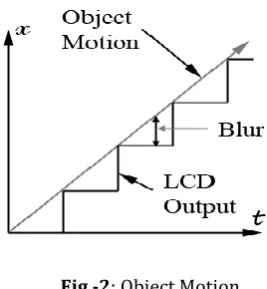
[image:2.595.86.220.180.325.2]scene while the LCD image output is in discrete values; thus, motion blur is due to the difference between expected and actual motion as shown in figure 2.
Fig -2: Object Motion
3. HUMAN VISUAL SYSTEM (HVS) MODELLING
The artificial Human Visual System is an attempt to model the natural human visual system to study the motion blur. Although LCD's output image is not actually blurry, it is perceived as one when it passes through the human visual system (HVS). It is modelled as a low pass filter and a motion tracker, as shown in figure 3. Since humans notice fast moving objects more than slow ones, the HVS includes a motion tracker. The fast moving image is filtered using the Low Pass Filter (LPF) to produce the blur effect. For instance, one can look left and right very quickly to blur the environment. Since the goal for the motion blur reduction algorithm is for humans to perceive a clear, sharp image, the HVS is an important filter to the process.
Fig -3: Human Visual System(HVS)
4. RELATED WORK
Previously proposed methods of reducing the effects of sample-and-hold LCD motion blur can be split up into three groups. All three offer incremental improvements (at least over a limited range of content) along with significant downsides.
1. Flashing the LCD backlight at a faster rate than the frame period allows the LCD to behave more like a scanning CRT. This method, proposed by Phillips, considerably reduces the amount of motion blur. Unfortunately, just as with a CRT, flashing the backlight contributes to viewer eyestrain and reduces the superior contrast of the LCD.
2. Increasing the frame rate reduces the hold time and, hence, the motion blur. This realization has motivated multiple attempts at doubling the frame rate by interpolating between frames and inserting black data between frames. Each of these methods has their own disadvantages including: requiring accurate motion estimation, raising the black level of the LCD, and only moderate performance, respectively. Furthermore, doubling the frame rate requires the LCD to operate at least two times as fast as current rates.
3. Motion-Compensated Inverse Filtering (MCIF) is a similar approach to the one we consider. MCIF involves estimating the motion and then applying a high-pass filter along that direction with a gain that depends on the rate of motion. This simple approach only works on limited content and is very sensitive to motion vector errors.
[image:2.595.58.271.612.678.2]© 2016, IRJET | Impact Factor value: 4.45 | ISO 9001:2008 Certified Journal | Page 1421 however, it will not eliminate it completely as, even with a
shorter hold time, fast motion sequences will still exhibit some blurring. Fortunately, proposed signal processing approach can be used in conjunction with these faster LCD driving methods to further improve the quality of the moving image. The high-quality motion vectors calculated for motion-compensated interpolation can be used by our signal processing approach, dramatically reducing the complexity of our procedure.
5.PROPOSED METHOD
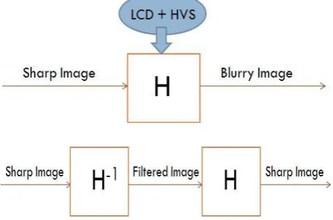
[image:3.595.41.282.384.543.2]The goal for the signal processing approach is to invert LCD response and human visual system (HVS) so that the resulting image appears sharp. The ideal approach is shown below in figure 4.
Fig -4: Signal processing approach
The LCD plus HVS can be grouped together as filter H. Ideally, the system would invert H to form H-1, and the resulting image from the LCD screen would appear to be sharp. This way, the viewer will perceive crisp, clear images on a LCD screen. Since the original blurry output image is a convolution of the images and H filter, the inverted filter H-1 will have to be a deconvolution of the original filter H. Unfortunately, this ideal case cannot be implemented in a system due to the LCD and HVS models.These LCD and HVS models are modelled as sinc functions. Since a sinc functions have zeros present in the frequency domain, it is
non-invertible. Therefore, the ideal case is unattainable. In response, this signal processing approach tries to come as close to the inverted case as possible.
6.RICHARDSON–LUCY(RL) ALGORITHM
A commonly used iterative method for deconvolution of images with an estimated point spread function (PSF) is the RL algorithm.
Where is the output image at time step is the original input image, and s( ) is the motion blur PSF
which operates in the direction of the motion vector . The blurring PSF is simply an ideal LPF with widths and along the x and y directions, respectively. Each of the nonzero elements in the PSF has value (1/ For the ratio in above equation, we define 0/0≡1.The RL algorithm converges to the maximum likelihood solution assuming Poisson counting statistics. Even though the pixel values of many natural images and sequences do not follow a Poisson distribution, this assumption gives us many desirable properties of our converged solution.
© 2016, IRJET | Impact Factor value: 4.45 | ISO 9001:2008 Certified Journal | Page 1422
7.BLOCK DIAGRAM OF THE PROPOSED METHOD
The video signal first goes through a motion estimation (ME)
stage. The Scaled Gradient Magnitude (SGM) metric module
then uses the resulting motion vectors along with the original
video signal to produce the weighting factor (w) according to
equations (1) and (2). The weighting factor is then used to
combine the result of the RL deconvolution module with the
original signal to produce the final image, which is then sent to
the LCD.
7.1 Region of interest filtering
Using an incorrect s ( ) in the RL algorithm, as is the case
when motion vector errors are present, will result in amplified
noise particularly in the smooth regions of the frame. These are
also the same regions that have the least accurate motion vector
estimates since it is difficult to match subtle features in
successive frames during motion estimation.
In addition, studies have shown that unless objects in the frame
have significant details, the HVS does not track them
individually but instead tracks the global motion in the scene.
Within certain regions in which researchers are not very
sensitive to motion blur, they will avoid noise amplification by
accounting for these regions in our deconvolution procedure.
Completely excluding these regions, leads to temporal
inconsistencies when regions in successive frames are labelled
differently. In this paper, to overcome these problems
researchers used the SGM module.
7.2 Scaled Gradient Magnitude (SGM) Metric
In order to classify regions based on perceptual significance, the
scaled gradient magnitude (SGM) metric is used.
+ (1)
Where is the gradient operator in the respective direction. The
logic behind eq. lies in the fact that perceptually significant
regions tend to have strong edges and features that lie
perpendicular to the direction of motion and, hence, will have a
high SGM value. The SGM value calculated for every block is
used to weight the effect of the deconvolution procedure. Let
Ô( be the deconvolved image, and be the original frame,
we create the compensated image as
u =ω.Ô( +(1-ω). (2)
Where ω = min ((SGM / d ,1)) . In this formulation, d is a factor
set a priori according to the specifications of the LCD. As‘d’
increases, the deblurring procedure will tend to have a smaller
impact on the final image.
Our final algorithm thus becomes the following:
1. Estimate the motion vector ) for each block in the
frame.
2. Calculate the SGM for that block.
3. Apply the RL algorithm with s( ) .
4. Combine with the original image using the equation for
compensated image above.
8.RESULT AND DISCUSSION
In this paper, displayed a still image and thus applying the
Motion-Compensated Inverse Filtering( MCIF) method to the
entire frame and then simulating motion blur weighted with
respect to the perceptual significance of the regions will not
accurately represent the output of the MCIF-HVS system. For
the purpose of comparison of the results of MCIF and
Richardson–Lucy(RL) methods, researchers used the motion
© 2016, IRJET | Impact Factor value: 4.45 | ISO 9001:2008 Certified Journal | Page 1423
noise suppression and the RL algorithm (with ten iterations) to
the entire image without region of interest filtering. Then motion
blur is simulated on these resulting two images by blurring the
entire image with the motion blur kernel calculated from the
motion vector information. The results for both RL method and
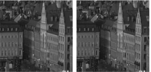
the MCIF method are shown below (Fig. 5). Looking at the
resulting images, we see that the windows in the centre of the
image processed using the RL methods are much sharper than
[image:5.595.36.284.264.382.2]those in the MCIF method.
Fig -5: Enlarged version of the resulting image after pre-processing with the (left) MCIF method and the (right) RL method.
9. CONCLUSIONS
LCDs have shown great promise in the consumer market but are unfortunately still plagued with the problem of motion blur. It is due to the problem of sample and hold characteristics of the display itself. In the proposed system the blurring phenomenon is limited to an extent by using the de-convolution algorithm along with the information obtained from motion vectors calculated from the scene. Since this de-blurring algorithm does not completely remove the LCD motion blur problem, more steps will be taken to improve the algorithm or incorporate it with other existing technologies. To make the inversion more ideal, parameters will be adjusted based on motion vector error calculations and human subject results.
REFERENCES
[1] M. Biswas, “Content adaptive video processing
algorithms for digital TV,” Ph.D. dissertation, Univ. California, San Diego, 2005.
[2] S. Har-Noy and T. Q. Nguyen, “A deconvolution method
for LCD motion blur reduction,” presented at the IEEE Int. Conf. Image Processing,2006.R. Nicole, “Title of paper with only first word capitalized,” J. Name Stand. Abbrev., in press.
[3] L. B. Lucy, “An iterative technique for the rectification of
observed distributions,” Astron. J., vol. 79, no. 6, Jun. 1974.
[4] M. Klompenhouwer and L. J. Velthoven, “Motion blur
reduction for liquid crystal displays: Motion compensated inverse filtering,” presented at the SPIE-IS&T Electronic Imaging, 2004.
[5] H. Pan, X.-F. Feng, and S. Daly, “Quantitative analysis of