3521
HYBRID OF MULTI-CAR ELEVATOR SYSTEM AND
DOUBLE-DECK ELEVATOR SYSTEM
1YEONG CHERNG LIEW, 2CHENG SIONG LIM, 3MICHAEL LOONG PENG TAN,
4CHEE WEI TAN
1, 2, 3, 4 Faculty of Electrical Engineering, Universiti Teknologi Malaysia, 81310 UTM Johor Bahru,
Johor, Malaysia
E-mail: 1[email protected], 2[email protected], 3[email protected], 4[email protected]
ABSTRACT
Multi-car elevator system is a new breakthrough in an elevator system in 2001. It has broken the traditional concept of developing only one elevator car in an elevator shaft. Multi-car elevator system can have more than one elevator car moving in an elevator shaft and it has improved a lot in minimizing the waiting time of passengers if compared with only one elevator car in an elevator shaft. The main advantage of multi-car elevator system is to reduce the construction cost where 30% of the core-tube area of the elevator system is made up of shaft. By developing multi-car elevator system, many of elevator shafts need not to be developed and it still can perform about the same efficiency in serving passengers. However, it is still not able to transport a large number of passengers efficiently if the passengers are calling from the same floor, especially during the up-peak traffic. For that reason, the feature of double-deck elevator system is integrated into multi-car elevator system to develop a new hybridized elevator system called “Hybrid of multi-car elevator system and double-deck elevator system” to solve the limited car capacity problem. The performance of both systems, the hybridized elevator system and the multi-car elevator system is simulated. The result shows that the average journey time of the hybridized elevator system is shorter than the multi-car elevator system in all the three traffic modes, i.e. up-peak, down-peak and inter-floor traffics. For the up-peak traffic mode of the hybridized elevator system, it manages to achieve the best result of 33.5% shorter of the average journey time compared to the multi-car elevator system.
Keywords: Elevator System, Transport Capacity, Multi-Car Elevator System, Double-Deck Elevator
System, Hybridizing
1. INTRODUCTION
The elevator system is a transportation system used for transporting passengers in a multi-storey building. The most common challenges encountered in elevator system are minimizing the waiting time of passengers and the limited transport capacity of an elevator car. Nowadays, the most recent and common elevator systems that have been implemented so far in the real world are Single-Deck Elevator System (SDES), Double-Single-Deck Elevator System (DDES) and Multi-Car Elevator System (MCES) [1–3]. SDES is broadly known, being the first elevator system in the multi-storey building. It has the simplest design, only one single-deck elevator car in each elevator shaft, in comparison to the other two elevator systems.
DDES is a modification to SDES that is purposely designed for high-rise buildings [4]. As
3522 The implementation of MCES is a new breakthrough to the existing elevator systems in the year 2002. Its main purpose is to reduce the construction cost of building extra elevator shafts [6]. It is implemented by allowing more than one elevator car in an elevator shaft instead of using extra elevator shafts with only one elevator car. This special feature of MCES enables the hall calls from different floors can be answered at the same time with different elevator cars within the same elevator shaft. Hence, the waiting time of passenger has been greatly reduced. However, it is a very complex elevator system as it needs to consider many problems such as car collision, live-lock and reversal problems [7]. Besides, it is still not able to transport a large number of passengers efficiently if the passengers are calling from the same floor, especially during the up-peak traffic. For that reason, the feature of double-deck elevator system is integrated into multi-car elevator system to develop a new hybridized elevator system. This research is to find out the efficiency of the hybridized elevator system as compared to MCES. It is time saving and lower cost to compare the performance of hybridized elevator system and MCES through simulation.
2. PRIOR WORK
The most recent and related prior work was done by Hiroki Ishihara [8]. He benchmarked two elevator systems, namely SDES and MCES. The control methods used in SDES and MCES were selective collective control and dynamic zoning, respectively. The number of elevator shaft in SDES was three to six while for MCES was fixed to three elevator shafts. Both elevator systems were tested in three traffics which were inter-floors, up-peak and down-peak. In general, the performance of MCES was better than SDES no matter in whichever traffic if the numbers of elevator shafts are kept the same.
The main difference between our work and the mentioned prior work is the benchmarked elevator systems. In this paper, the benchmarked elevator systems are MCES and hybridized elevator system while the prior work focused on SDES and MCES. The capacity of elevator car, the number of elevator shaft and the simulation parameters setup are also different.
3. PROBLEM STATEMENT
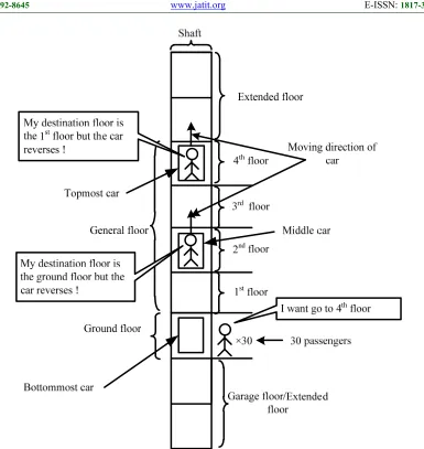
This paper is aimed at improving certain problems that occurred in MCES. During the up-peak traffic, there are many passengers waiting at the ground floor. Although MCES has multiple cars in an elevator shaft, it is still inefficient in transporting large numbers of passengers within a short time. Figures 1 to 3 demonstrate the cases in the dispatch strategies of MCES which consists of three elevator cars during the up-peak traffic.
In case 1, the bottommost elevator car is assigned to go to the ground floor to serve passengers, while the other elevator cars are assigned to serve passengers at general floors. If the bottommost elevator car is assigned to serve passengers at the ground floor, only a certain numbers of the passengers are served. This is because one elevator car has a limited passenger capacity and therefore unable to serve a large number of passengers. There are also no other elevator cars standing by at the garage floor to be assigned to the ground floor to serve the rest of the passengers. In addition, if the above elevator cars are travelling in the downward direction, the bottommost elevator car that is travelling in an upward direction undergoes a reversal problem [9], [10]. Hence, this increases the travelling time of passengers.
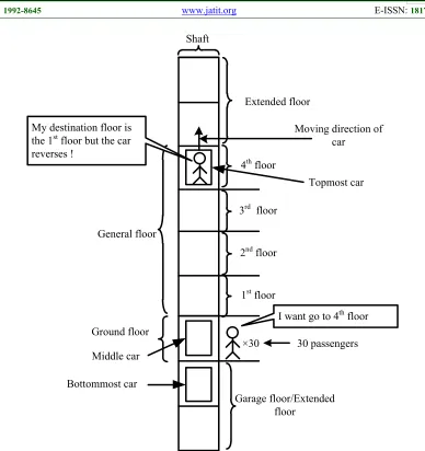
In case 2, the middle elevator car is assigned to go to the ground floor to serve passengers, while the elevator cars above the middle ones are assigned to serve passengers at general floors and the elevator cars below the middle ones are assigned to wait at the garage floor. Although there are elevator cars standing by at the garage floor which can serve the rest of the passengers at the ground floor, there is still the problem of reversal if there are elevator cars above the middle car moving in a downward direction [11].
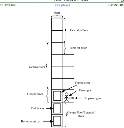
3523 Therefore, case 3 is the best option among all the cases if the MCES aims to maximize the efficiency of transporting a large number of the passengers during the up-peak traffic. However, its efficiency is still poor as time elapses while waiting for the elevator cars before they reach the ground floor to serve passengers. While waiting, the elevator cars at the garage floor have become idle. This situation is very different from DDES. During the up-peak traffic in the DDES, passengers are required to decide whether they should wait at the ground floor or at the first floor. For the passengers whose desired floors are odd numbers, they just need to wait at the ground floor to take the lower cage service. Meanwhile, for the passengers whose desired floors are even numbers, they need to go to the first floor by using an escalator and wait for taking the upper cage service. When the elevator car arrives, both passengers waiting at the ground floor and the first floor can be served simultaneously [12–14]. Figure 4 shows the working principle of DDES during the up-peak traffic.
4. PROPOSED METHOD
The idea of DDES is introduced to the MCES to improve the problem of limited transport capacity. Hence, a hybrid of DDES and MCES is developed. Since there are two types of elevator system hybridized together, two types of controlling method are adopted as well. For the MCES part, a method of dynamic zoning which proposed by Ishihara in 2013 is adopted due to its flexibility in transporting passengers and its ability to prevent collision between elevator cars [15–17]. For the DDES part, double running mode is adopted because it has the least number of stops when carrying passengers compared to the semi-double and single running modes [18–21]. In this mode, the upper or lower cage serves the passengers to odd or even floors respectively. Figure 5 shows the structure of the hybridized elevator system.
3.1 Elements in Hybridized Elevator System
The hybridized elevator system is the hybrid of both MCES and DDES, hence the elements found in the hybridized elevator system comprise both elements of MCES and DDES as well. The descriptions of the elements of the hybridized elevator system are shown below.
3.1.1 Floor
The level of the building. Ground floor is the most frequently used floor as it is the only point of exist
or entry to the building, hence it is highly demanded. The ground floor is named “terminal floor” whereas the rest of the floors, which experience normal traffic demands are named “general floor”.
3.1.2 Elevator car
It is a means of transportation intended for carrying passengers to desired floors. There can be more than one elevator car in a shaft, compared to SCES which is limited to only one elevator car in a shaft.
3.1.3 Cage
It is the compartment in an elevator car which can only be found in DDES. There are two cages in DDES, i.e. upper cage and lower cage.
3.1.4 Elevator shaft
It is the space, or the pathway, for the elevator car to move.
3.1.5 Registration of destination floor
In order for the system to plan the schedule of answering the hall call, passengers are required to register the destination floor and the number of passengers in the hall before they enter into the elevator car.
3.1.6 Hall call
The call from the passengers at their departure floor.
3.1.7 Car call
The call from the passengers to their desired floor. It can be called during the registration of destination floor or inside the elevator car.
3.1.8 Garage floor
It is designed for the purpose to let the higher elevator cars reach the ground floor. If there are m
elevator cars, there must be (m-1) garage floors [21].
3.2 Description of zone
The zone is a section of the pathway in a shaft assigned to an elevator car. The elevator car is necessary to serve all the hall calls that occur in this zone. The other elevator cars which are in the same shaft are not permitted to enter this zone. The zone has the following elements.
3.2.1 Direction
The direction of a zone depends on the assignment of the first hall call to the corresponding elevator car.
3.2.2 Top floor
It is the highest floor in a zone.
3.2.3 Bottom floor
It is the lowest floor in a zone.
3524 or shortened based on the hall calls assignment or the movement of a car to carry the passenger. After all the calls are answered, the zone is disappeared. By following these rules, the overlapping between zones is not possible.
3.3 Assignment of Hall Call
The elevator group controller is responsible for the hall call assignment. It is called repeatedly and performs the following steps to assign the hall calls to the elevator cars.
3.3.1 Step 1
Identify a list of hall calls which are unassigned.
3.3.2 Step 2
The waiting time of passenger for all pairs of the elevator cars and the assigned hall calls are measured.
3.3.3 Step 3
The elevator car is assigned among the pairs to answer the hall call by taking the minimum waiting time.
3.3.4 Step 4
The zone is allocated based on the assigned hall call.
3.3.5 Step 5
The other elevator cars, which are in the section of the allocated zone in the same shaft, are moved to the outside of the zone.
3.3.6 Step 6
Remove the hall call which has been assigned to the elevator car from the list of unassigned hall call.
3.3.7 Step 7
Repeat steps (2) to (6) if it still has assignable pairs.
In order for the elevator system to avoid collision between elevator cars and overload of an elevator car, the elevator group controller has to fulfill equations (1) and (2) before the hall call is assigned to the elevator car.
> or > (1)
≥ + or ≥ + (2)
where:
elevator car j is not the same as elevator car k (j k).
and represent the bottom floor of elevator car
j and elevator car k respectively.
and represent the top floor of elevator car j
and elevator car k respectively.
and represent the number of passengers in elevator car j and elevator car k respectively.
and represent the number of passengers for hall call j and hall call k respectively.
represents the capacity of an elevator car.
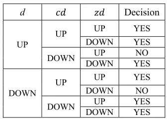
The elevator group controller also needs to fulfill the set (3) to avoid the reversal problem during assigning the hall call.
( ∩ )∪( ∩ ∩ )∪( ∩ ∩ )∪
( ∩ ) (3)
where:
represents the elevator car moving up. represents the elevator car moving down.
represents the elevator car moving up to answer the hall call.
represents the elevator car moving down to answer the hall call.
[image:4.612.333.501.326.447.2]represents the direction of zone, up. represents the direction of zone, down.
Table 1: Decision of Hall Call Assignment.
d Decision
UP
UP UP YES DOWN YES DOWN DOWN UP YES NO
DOWN
UP UP YES DOWN NO
DOWN DOWN UP YES YES
has three elements, i.e. ∈ "UP", "DOWN", "STOP" . If the elevator car is moving up, then is "UP". If the elevator car is moving down, then is "DOWN". If the elevator car is at stationary, then is "STOP".
has two elements, i.e. ∈ "UP", "DOWN" . If is the departure floor of the zone and is the destination floor of the zone, then
is "UP". It is contrary for as "DOWN".
has two elements, i.e. ∈ {"UP","DOWN" }. If the current position of the elevator car is lower than the departure floor of the hall call, then is "UP". It is contrary for as "DOWN".
3525 The hybridised elevator system is different from MCES because the elevator car is not a single-deck but double-single-deck. Hence, the working principle of DDES needs to be taken into account as well. Double running mode is chosen as the working principle of DDES and applied in the hybridised elevator system. This running mode serves only the odd car call by an upper cage while the even car call is served by a lower cage. During up-peak traffic, passengers are required to decide whether they should wait at the ground floor or at the first floor. For passengers whose desired floors are odd numbers, they need to wait at ground floor level to take the lower cage service. Meanwhile, for passengers whose desired floors are even numbers, they need to go to the first floor by using an escalator and wait to take the upper cage service.
5. SIMULATION EXPERIMENTS
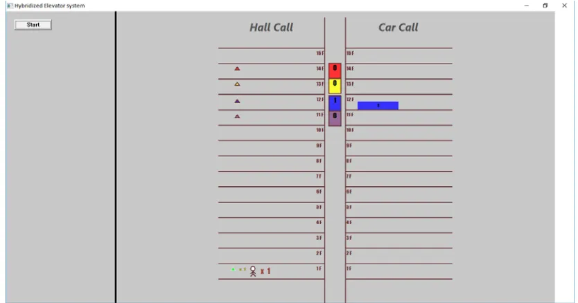
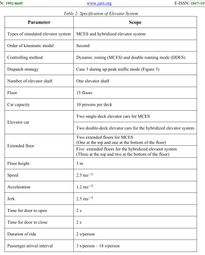
The elevator simulator used for running the experiment is developed by Microsoft Visual Studio 2013 using windows API and C++ language. It is used to evaluate the two elevator systems, i.e. MCES and the hybridized elevator system. The elevator simulator has the following specifications, as shown in Table 2.
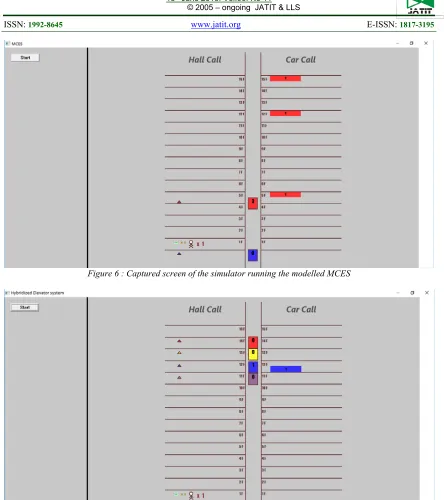
Both of the elevator systems are running in three traffic modes, i.e. up-peak traffic, down-peak traffic and inter-floor traffic. During up-peak traffic, the hall calls that occur at the ground floor are generated at high probability. During the down-peak traffic, the hall calls in which passengers are going to the ground floor are generated at high probability. During inter-floor traffic, the hall calls are generated randomly at any floors [8]. The occurrences of hall calls generated from the simulator are the same for both elevator systems and the total number of hall call generated is 100. Figure 6 and Figure 7 show the captured screen of the simulator of MCES and the hybridized elevator system respectively.
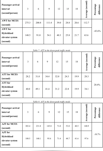
The performance of the elevator systems is evaluated by the index of average waiting time (AWT), average travel time (ATT) and average journey time (AJT) [23–28]. AWT is the average time taken by passengers to wait for the elevator car to arrive after the hall calls are generated. ATT is the average time taken by the elevator car to carry passengers from their departure floor to desired floor. AJT is the summation of AWT and ATT.
The simulation results with the mentioned specifications are listed in Tables 3 to 11. Figures 8 to 16 show the results in plotted graphs.
6. DISCUSSION
From the obtained results, it can be seen that the overall performance of the hybridized elevator system is better than MCES. The average AJT of all the passenger arrival intervals has decreased 33.5% in the up-peak traffic mode, 30.7% in the down-peak traffic mode and 13.0% in the inter-floor traffic mode. Since the AJTs of hybridized elevator system in all the traffic modes decrease as compared with MCES, it can be concluded that the hybridized elevator system performs faster than MCES in serving passengers.
However, there is also the interval when the performance of the hybridized elevator system is about the same or even worse than MCES. This occurs when the passenger arrival interval is between 12 to 18 seconds per person. In this arrival interval, the demand of hall call is low, single-deck elevator cars of the MCES are capable to cope with low hall call demand. For the hybridized elevator system, some of the time elapses if the odd and even desired floors are requested from passengers at the same floor. Assuming an elevator car is moving up to serve the calling from a floor with the passengers of both odd and even desired floors, the lower cage needs to wait for the upper cage to complete serving the passengers with even desired floors before it can serve the passengers with odd desired floors. The same situation can happen when the elevator is moving down. This causes the waiting time of passenger to increase. The MCES performs better in this range of passenger arrival interval because it only has one cage which can serve both odd and even floors without causing a longer waiting time.
3526 the hybridized elevator system for serving the car calls occur at two consecutive floors where the elevator car can load or unload the passengers at the odd floor and even floor at the same time. This advantage can greatly reduce the travel time of passengers and the number of stops needed by the elevator car.
Among the three traffic modes, the hybridized elevator system demonstrates an obvious performance gain over MCES in the up-peak traffic mode. This is because the hybridized elevator system can accommodate double car capacity, loading a large number of passengers at the ground floor and the first floor simultaneously.
7. LIMITATIONS AND ASSUMPTIONS
The capability of the elevator simulator was limited to the simulation of a building with 15 floors and single elevator shaft. Besides, in order to reduce the complexity of the elevator system, the elevator simulator limits the number of elevator cars to two for both simulated elevator systems.
For the simplicity of the elevator systems, it is assumed the time related to the human activities can be ignored. Besides, the time for docking and undocking the elevator cars are also ignored due to its insignificant influence.
8. CONCLUSION
After the elevator simulation was carried out, it was verified that the performance of the hybridized elevator system is better than MCES, with the advantage of accommodating double the passenger capacity. The average AJT of hybridized elevator system has decreased 33.5% in the up-peak traffic mode, 30.7% in the down-peak traffic mode and 13.0% in the inter-floor traffic mode. It has shown that the hybridized elevator system has greatly improved the performance of elevator system in serving passenger compared with MCES especially during the up-peak traffic mode. The hybridized elevator system had a poor performance when the passenger arrival interval was between 12s/person to 18s/person. With this exception, the performance of the hybridized elevator system is superior to the MCES.
9. DIRECTION FOR FUTURE WORK
Hybrid of MCES and DDES is a new concept which is yet implemented in the real world.
From the simulation, its real world performance gain can be predicted. The results show that the hybridized elevator system has high efficiency when passenger arrival interval is short especially during up-peak traffic mode but its efficiency is low when passenger arrival interval is long. Therefore, it is suggested that the hybridized elevator system to have transformation capability to work as single-deck or double-deck elevator system to suit passengers traffic pattern. The transformation can be done by automating the assembling and dissembling processes of the elevator decks. When two single-decks are assembled together, double-deck elevator system is formed. On the other hand, when a double-deck is dissembled into two single-decks, single-deck elevator system is formed. The unused decks can be parked into garage floors so that the elevator cars can have more moving space inside an elevator shaft. As a conclusion, a transformable hybridized elevator system can further boast up the transportation efficiency.
ACKNOWLEDGEMENTS:
The authors would like to acknowledge the financial support from Fundamental Research Grant Scheme (vote no R.J130000.7823.4F314) of the Ministry of Higher Education (MOHE), and Research University Grant (vote on Q.J130000.2523.13H20) from Research Management Centre (RMC) of Universiti Teknologi Malaysia.
REFRENCES:
[1] Walker, Joseph C., and Bruce A. Powell, “Method of operation for double-deck elevator system”, US Patent No. 5,844,179, (United State), December 1, 1998.
[2] Crites, Robert H., and Andrew G. Barto, “Elevator group control using multiple reinforcement learning agents”, Machine
learning, Vol. 33, No. 2, 1998, pp. 235-262.
[3] Gale, John, “ThyssenKrupp's TWIN lift system part one: The introduction”, Elevator World, Vol. 51, No. 7, 2003, pp. 51-52.
[4] Naitoh, Yoshiaki, “Double deck elevator with adjustable floor height”, U.S. Patent No.
6,802,396, (United State), October 12, 2004.
3527 network programming”, ICCAS-SICE, IEEE, 2009, pp. 3870-3873.
[6] Sachs, Harvey M., “Opportunities for elevator energy efficiency improvements”, DC: American Council for an Energy-Efficient
Economy, (Washington), April, 2005.
[7] Takahashi, Satoshi, Hajime Kita, Hiromichi Suzuki, Takeshi Sudo, and Sandor Markon, “Simulation-based optimization of a controller for multi-car elevators using a genetic algorithm for noisy fitness function”, Evolutionary Computation, 2003. CEC'03. The 2003
Congress on, Vol. 3, IEEE, 2003, pp.
1582-1587.
[8] Ishihara, Hiroki, and Shohei Kato, “The effectiveness of dynamic zoning in multi-car elevator control”, Consumer Electronics (GCCE), 2014 IEEE 3rd Global Conference on, IEEE, October 7, 2014, pp. 601-604. [9] Smedinga, Rein, “Locked discrete event
systems: how to model and how to unlock”,
Discrete Event Dynamic Systems, Vol. 2, No. 3,
1993, pp. 265-297.
[10] McHoes, Ann, and Ida M. Flynn, “Understanding operating systems”, Cengage
Learning, October 9, 2013.
[11] Tanaka, Shunji, and Masashi Watanabe, “Improvement of the optimization-based collision avoidance method for reversal-and livelock-free operation in multi-car elevator systems”, SICE Annual Conference 2010,
Proceedings of. IEEE, August 18, 2010, pp.
844-848.
[12] Yu, Lu, Jin Zhou, Fengming Ye, Shingo Mabu, Kaoru Shimada, Kotaro Hirasawa, and Sandor Markon, “Double-deck elevator system using genetic network programming with genetic operators based on pheromone information”,
Proceedings of the 10th annual conference companion on Genetic and evolutionary
computation, ACM, July 12, 2008, pp.
2239-2244.
[13] Hirasawa, Kotaro, Toru Eguchi, Jin Zhou, Lu Yu, Jinglu Hu, and Sandor Markon, “A double-deck elevator group supervisory control system using genetic network programming”, IEEE Transactions on Systems, Man, and Cybernetics, Part C (Applications
and Reviews), Vol. 38, No. 4, IEEE, July,
2008, pp. 535-550.
[14] Yu, Lu, Jin Zhou, Shingo Mabu, Kotaro Hirasawa, Jinglu Hu, and Sandor Markon, “Double-deck elevator group supervisory control system using genetic network
programming with ant colony optimization”,
Evolutionary Computation, 2007. CEC 2007.
IEEE Congress on, IEEE, September 25, 2007,
pp. 1015-1022.
[15] So, Albert TP, J. K. L. Yu, and W. L. Chan, “Dynamic zoning based supervisory control for elevators”, Control Applications, 1999. Proceedings of the 1999 IEEE International
Conference on, Vol. 2, IEEE, 1999, pp.
1591-1596.
[16] Li, Zhonghua, Zongyuan Mao, and Jianping Wu, “Research on dynamic zoning of elevator traffic based on artificial immune algorithm”,
Control, Automation, Robotics and Vision
Conference, 2004. ICARCV 2004 8th, Vol. 3,
IEEE, December 6, 2004, pp. 2170-2175. [17] Ishihara, Hiroki, and Shohei Kato, “Multi-car
elevator control using dynamic zoning”,
Consumer Electronics (GCCE), 2013 IEEE
2nd Global Conference on, IEEE, October 1,
2013, pp. 265-297.
[18] Zhou, Jin, Lu Yu, Shingo Mabu, Kaoru Shimada, Kotaro Hirasawa, and Sandor Markon, “Double-deck elevator systems adaptive to traffic flows using genetic network programming”, Evolutionary Computation, 2008. CEC 2008.(IEEE World Congress on Computational Intelligence). IEEE Congress on, IEEE, June 1, 2008, pp. 773-778.
[19] Zhou, Jin, Lu Yu, Shingo Mabu, Kotaro Hirasawa, Jinglu Hu, and Sandor Markon, “Double-deck elevator systems using genetic network programming based on variance information”, SICE, 2007 Annual Conference, IEEE, September 17, 2007, pp. 163-169. [20] Yu, Lu, Shingo Mabu, Jin Zhou, Shinji Eto,
and Kotaro Hirasawa, “Double-Deck Elevator Systems with idle cage assignment using Genetic Network Programming”, Systems Man and Cybernetics (SMC), 2010 IEEE
International Conference on, IEEE, October
10, 2010, pp. 1987-1994.
[21] Zhou, Jin, Lu Yu, Shingo Mabu, Kotaro Hirasawa, Jinglu Hu, and Sandor Markon, “Double-deck elevator systems using Genetic Network Programming with reinforcement learning”, Evolutionary Computation, 2007.
CEC 2007. IEEE Congress on, IEEE,
September 25, 2007, pp. 2025-2031.
[22] Yamashita, Sakurako, Masafumi Iwata, Shiro Hikita, and Kiyotoshi Komaya, “A study on design method of multi-car elevator system”,
IEEJ Transactions on Industry Applications,
3528 [23] Nikovski, Daniel, and Matthew Brand, “Exact
calculation of expected waiting times for group elevator control”, IEEE transactions on
automatic control, Vol. 49, No. 10, IEEE,
October, 2004, pp. 1820-1823.
[24] Zheng, Yi Peng, Zu Tao Zhang, and Hong Xu, “A Novel Intelligent Elevator Group Control Algorithm Based on Corridor Passenger Detection and Tracking”, Applied Mechanics
and Materials,, Vol. 336, Trans Tech
Publications, 2013, pp. 815-819.
[25] Fernandez, J., Pablo Cortés, Jesús Muñuzuri, and José Guadix, “Dynamic fuzzy logic elevator group control system with relative waiting time consideration”, IEEE
Transactions on Industrial Electronics, Vol. 61,
No. 9, IEEE, September, 2014, pp. 4912-4919. [26] Tang, Hai-Yan, Bao Ding, Wei-Gui Qi, and
Yong-Ming Zhang, “Optimization of elevator group control scheduling with multi-strategy switch”, Machine Learning and Cybernetics,
2008 International Conference on, Vol. 4,
IEEE, July 12, 2008, pp. 2067-2072.
[27] Tartan, Emre Oner, Hamit Erdem, and Ali Berkol, “Optimization of waiting and journey time in group elevator system using genetic algorithm”, Innovations in Intelligent Systems and Applications (INISTA) Proceedings, 2014
IEEE International Symposium on, IEEE, June
23, 2014, pp. 361-367.
[28] Yang, Cheng Hui, “Multi-objective Programming and Time Optimal Algorithm Research”, Advanced Materials Research, Vol. 852, Trans Tech Publications, 2014, pp. 715-719.
3529
3530 Ground floor
Garage floor/Extended floor
General floor
Shaft
Extended floor
4thfloor
I want go to 4thfloor
3rd floor
2ndfloor
1stfloor
My destination floor is the 1stfloor but the car
reverses !
Moving direction of car
×30 30 passengers
Topmost car
[image:10.612.112.500.69.481.2]Bottommost car Middle car
3531
3532
Figure 4 : The working principle of DDES during the up-peak traffic
[image:12.612.97.514.419.638.2]3533
Table 2: Specification of Elevator System
Parameter Scope
Types of simulated elevator system MCES and hybridized elevator system
Order of kinematic model Second
Controlling method Dynamic zoning (MCES) and double running mode (DDES)
Dispatch strategy Case 3 during up-peak traffic mode (Figure 3)
Number of elevator shaft One elevator shaft
Floor 15 floors
Car capacity 10 persons per deck
Elevator car
Two single-deck elevator cars for MCES
Two double-deck elevator cars for the hybridized elevator system
Extended floor
Two extended floors for MCES
(One at the top and one at the bottom of the floor) Five extended floors for the hybridized elevator system (Three at the top and two at the bottom of the floor)
Floor height 3 m
Speed 2.5 m
Acceleration 1.2 m
Jerk 2.5 m
Time for door to open 2 s
Time for door to close 2 s
Duration of ride 2 s/person
3534
[image:14.612.91.522.343.571.2]Figure 6 : Captured screen of the simulator running the modelled MCES
3535
Table 3: AWT in the up-peak traffic mode
Passenger arrival interval
(second/person)
3 6 9 12 15 18
Aver
age (second)
Percentage difference
AWT for MCES
(second) 207.1 120.0 35.0 21.4 19.9 17.3 70.1
-51.2%
AWT for Hybridized elevator system (second)
80.6 39.1 25.0 23.3 19.8 17.2 34.1
Table 4: ATT in the up-peak traffic mode
Passenger arrival interval
(second/person)
3 6 9 12 15 18
Aver
age (second)
Percentage difference
ATT for MCES
(second) 42.0 46.3 40.5 30.2 23.7 20.3 33.8
3.3%
ATT for
Hybridized elevator system (second)
50.7 56.4 33.4 28.9 21.6 18.7 34.9
Table 5: ATT in the down-peak traffic mode
Passenger arrival interval
(second/person)
3 6 9 12 15 18
Aver
age (second)
Percentage difference
AJT for MCES
(second) 249.2 166.3 75.5 51.6 43.5 37.6 103.9
-33.5%
AJT for Hybridized elevator system (second)
3536
Table 6: AWT in the down-peak traffic mode
Passenger arrival interval
(second/person)
3 6 9 12 15 18
Aver
age (second)
Percentage difference
AWT for MCES
(second) 275.3 200.8 111.4 39.0 28.8 20.6 112.7
-43.6%
AWT for Hybridized elevator system (second)
[image:16.612.88.524.105.742.2]148.5 91.0 54.1 40.3 25.8 21.7 63.6
Table 7: ATT in the down-peak traffic mode
Passenger arrival interval
(second/person)
3 6 9 12 15 18
Aver
age (second)
Percentage difference
ATT for MCES
(second) 28.2 31.0 34.4 32.0 24.3 19.9 28.3
20.4%
ATT for Hybridized elevator system (second)
40.0 49.1 41.4 31.2 22.8 19.9 34.1
Table 8: AJT in the down-peak traffic mode
Passenger arrival interval
(second/person)
3 6 9 12 15 18
Aver
age (second)
Percentage difference
AJT for MCES
(second) 303.4 231.8 145.8 71.0 53.0 40.5 140.9
-30.7%
AJT for Hybridized elevator system (second)
3537
Table 9: AWT in the inter-floor traffic mode
Passenger arrival interval
(second/person)
3 6 9 12 15 18
Aver
age (second)
Percentage difference
AWT for MCES
(second) 191.7 130.7 84.5 39.2 31.3 14.4 82.0
-17.7%
AWT for Hybridized elevator system (second)
148.5 104.0 73.3 37.4 24.1 17.5 67.4
Table 10: ATT in the inter-floor traffic mode
Passenger arrival interval
(second/person)
3 6 9 12 15 18
Aver
age (second)
Percentage difference
ATT for MCES
(second) 40.2 37.3 34.2 22.4 19.6 14.8 28.1
0.8%
ATT for
Hybridized elevator system (second)
47.7 40.6 29.7 20.9 16.0 14.9 28.3
Table 11: AJT in the inter-floor traffic mode
Passenger arrival interval
(second/person)
3 6 9 12 15 18
Aver
age (second)
Percentage difference
AJT for MCES
(second) 231.9 167.9 118.8 61.6 50.9 29.2 110.0
-13.0%
AJT for Hybridized elevator system (second)
3538
Figure 8 : Simulation results of AWT in the up-peak traffic mode
Figure 9 : Simulation results of ATT in the up-peak traffic mode
Figure 10 : Simulation results of AJT in the up-peak traffic mode 0
50 100 150 200 250
3s/p 6s/p 9s/p 12s/p 15s/p 18s/p
AWT (second)
Passenger arrival interval (second/person)
MCES
Hybridised elevator system
0 10 20 30 40 50 60
3s/p 6s/p 9s/p 12s/p 15s/p 18s/p
ATT (second)
Passenger arrival interval (second/person)
MCES
Hybridised elevator system
0 50 100 150 200 250 300
3s/p 6s/p 9s/p 12s/p 15s/p 18s/p
AJT (second)
Passenger arrival interval (second/person)
MCES
3539
Figure 11 : Simulation results of AWT in the down-peak traffic mode
[image:19.612.87.528.40.728.2]Figure 12 : Simulation results of ATT in the down-peak traffic mode
Figure 13 : Simulation results of AJT in the down-peak traffic mode 0
50 100 150 200 250 300
3s/p 6s/p 9s/p 12s/p 15s/p 18s/p
AWT (second)
Passenger arrival interval (second/person)
MCES
Hybridised elevator system
0 10 20 30 40 50 60
3s/p 6s/p 9s/p 12s/p 15s/p 18s/p
ATT (second)
Passenger arrival interval (second/person)
MCES
Hybridised elevator system
0 50 100 150 200 250 300 350
3s/p 6s/p 9s/p 12s/p 15s/p 18s/p
AJT (second)
Passenger arrival interval (second/person)
MCES
3540
Figure 14 : Simulation results of AWT in the inter-floor traffic mode
[image:20.612.90.526.37.723.2]Figure 15 : Simulation results of ATT in the inter-floor traffic mode
Figure 16 : Simulation results of AJT in the inter-floor traffic mode 0
50 100 150 200 250
3s/p 6s/p 9s/p 12s/p 15s/p 18s/p
AWT (second)
Passenger arrival interval (second/person)
MCES
Hybridised elevator system
0 10 20 30 40 50 60
3s/p 6s/p 9s/p 12s/p 15s/p 18s/p
ATT (second)
Passenger arrival interval (second/person)
MCES
Hybridised elevator system
0 50 100 150 200 250
3s/p 6s/p 9s/p 12s/p 15s/p 18s/p
AJT (second)
Passenger arrival interval (second/person)
MCES