© 2017, IRJET | Impact Factor value: 5.181 | ISO 9001:2008 Certified Journal | Page 191
SECURITY FOR IDENTITY BASED IDENTIFICATION USING WATER
MARKING AND VISUAL CRYPTOGRAPHY
*1
Mrs. Ashwini K .,
*
2Mrs. Anita Madona M
*1
M.Phil Research Scholar, PG & Research Department of Computer Science & Information Technology Auxilium
College , Vellore, Tamil Nadu, India
*2
. Assistant Professor, PG & Research Department of Computer Science & Information Technology Auxilium
College, Vellore, Tamil Nadu, India
---***---Abstract: Security for identity based identification using
watermarking and visual cryptography gives ous the secure authentication for our access. To have a protective authentication, watermarking algorithm for embedding iris image and visual cryptography technique is used. To overcome such problem we can use the support vector machine which gives ous the high accuracy. And it involves two design methodologies, first is false acceptance rate
(FAR) and second is false rejection rate (FRR).To improve
existing algorithms to make the IRIS recognition accurately is possible on Noisy Iris Images. The iris recognition should be more accurate, an effective iris segmentation technique such as DCT, DWT, DFT etc., are used with the help of visual cryptography for noisy iris images. And particular user’s iris image is stored in the database. Feature Extraction Ratio of Co-efficient (ROC) Curves Validates MASEK and Ma to obtain the FAR result accurately. Binomial Distribution vector space is executed for FAR and FRR. Distribution Reliability in Ma and MASEK is applied in 128 bit blocks. At present, it works on .jpg format that should be increased to a lot more .gif, png format. And the encryption –decryption techniques should be changed as per emergence of new technologies
Keywords:
is false rejection rate, false acceptance rate, DCT, DWT, DFT, Encryption –Decryption Techniques, watermarking algorithmI. INTRODUCTION
The term biometrics refers to “Automated recognition of individuals based on their behavioral and biological characteristics”. There are several physiological as well as behavioral biometric characteristics like fingerprints, iris, face, hand, voice, gait, etc., depending on types of applications. Biometric traits are acquired by applying extracted sensors and distinctive features to form a biometric template in the enrollment process [1].
During verification authentication process or
identification (identification can be handled as a sequence of verifications and screenings) the system processes another biometric measurement which is compared against the stored templates yielding acceptance or rejection [3]. It is generally conceded that a substitute to
biometrics for positive identification in integrated security applications is non-existent.
Biometrics is the measurement and statistical
analysis of people's physical and behavioral
characteristics [2]. The technology is mainly used for identification and access control, or for identifying individuals that are under surveillance. The basic premise of biometric authentication is that everyone is unique and an individual can be identified by his or her intrinsic physical or behavioral traits [4][7].
There are two main types of biometric identifiers:
Physiological characteristics: The shape or
composition of the body.
Behavioral characteristics: The behavior of a
person.
Physiological characteristics used for biometric authentication include fingerprints; DNA; face, hand, retina or ear features; and odor.
The basic aim of this research study is to design an effective and secure technique for personal authentication using iris recognition and also evaluate the performance of the designed framework by comparing the performance of existing iris recognition system. The study also provides the iris template security mechanism to secure iris recognition system.
© 2017, IRJET | Impact Factor value: 5.181 | ISO 9001:2008 Certified Journal | Page 192
The major findings of the study can besummarized as under:
For making the iris recognition more accurate, an
effective iris segmentation technique for noisy iris images is proposed. And particular user’s iris image is stored in the database.
Feature Extraction ROC Curves Validates MASEK
and Ma to obtain the FAR result accurately.
Binomial Distribution vector space is executed for
FAR and FRR.
Distribution Reliability in Ma and MASEK is
applied in 128 bit blocks.
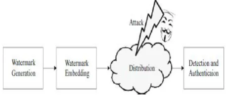
Visual cryptography is a cryptographic technique which allows visual information to be encrypted in such a way that the decryption can be performed by the human visual system. Visual cryptography scheme mainly depends on pixel expansion and contrast. Pixel expansion refers to the number of sub pixels in the generated shares that represents a pixel of the original input image. It represents the loss in resolution from the original picture to the shared one. Contrast is the relative difference in weight between combined shares that come from a white pixel and a black pixel in the original image. Plenty of research has been made to improve the performance of
[image:2.595.49.278.429.532.2]basic visual cryptography scheme
.
Fig : Watermarking an image Detection
II. RELATIVE WORK
Iris recognition
Iris recognition is a method of identifying people based on unique patterns within the ring-shaped region surrounding the pupil of the eye. The iris usually has a brown, blue, gray, or greenish color, with complex patterns that are visible upon close inspection. Because it makes use of a biological characteristic, iris recognition is considered a form of biometric verification.
In iris recognition, the identification process is carried out by gathering one or more detailed images of the eye with a sophisticated, high-resolution digital camera at visible or infrared (IR) wavelengths, and then using a specialized computer program called a matching
engine to compare the subject's iris pattern with images stored in a database. The matching engine can compare millions of images per second with a level of precision comparable to conventional fingerprinting or digital fingers canning.
IRIS with Biometrics
Iris biometrics refers to “high confidence recognition of a person’s identity by mathematical analysis of the random patterns that are visible within the iris of an eye from some distance”. The iris is the annular area between the pupil and the sclera of the eye. In contrast to other biometric characteristics, such as fingerprints, the iris is a protected internal organ whose random texture is complex, unique, and very stable throughout life. Breakthrough work to create iris recognition algorithms was proposed by J. G. Daugman, University of Cambridge Computer Laboratory. Daugman’s algorithms for which he holds key patents form the basis of the vast majority of today’s commercially dispread iris recognition systems. Until now iris recognition has been successfully applied in diverse access control systems managing large-scale user database. For instance, in the UK project IRIS (Iris Recognition Immigration System), over a million frequent travelers have registered with the system for automated border-crossing using iris recognition. IRIS is in operation on different UK airports including London Heathrow and Gatwick, Manchester and Birmingham. While the registration process usually takes between 5 and 10 minutes enrolled passengers do not even need to assert their identity. They just look at the camera in the automated lanes crossing an IRIS barrier in about 20 seconds. Several other large-scale iris recognition systems have been successfully deployed.
IRIS Image Processing
© 2017, IRJET | Impact Factor value: 5.181 | ISO 9001:2008 Certified Journal | Page 193
a binary feature vector, which is commonly referred to asiris-code. While Daugman suggests applying 2D-Gabor filters in the feature extraction stage plenty of different methods have been proposed.
Genuine Acceptance Rate (GAR)
Several metrics exist when measuring the performance of biometric systems. Widely used factors include False Rejection Rate (FRR), False Acceptance Rate (FAR), and Equal Error Rate (EER). While the FRR defines the “proportion of verification transactions with truthful claims of identity that are incorrectly rejected”, the FAR defines the “proportion of verification transactions with wrongful claims of identity that are incorrectly confirmed” (ISO/IEC FDIS 19795-1). The Genuine Acceptance Rate (GAR) is defined as, GAR = 1 - FRR. As score distributions overlap, FAR and FRR intersect at a certain point, defining the EER of the system. According to intra- and inter-class accumulations generated by biometric algorithms, FRRs and FARs are adjusted by varying system thresholds. In general decreasing the FRR (b= increasing the GAR) increases the FAR and vice versa.
III. PREVIOUS IMPLEMENTATIONS
Improve the Security for Authentication
Capturing iris image
Eye capture and image acquisition generally play a crucial role in iris recognition. Poor quality of the image results in a radical increase of FRR, while GRR remains more or less the same as it is largely independent of image quality.
Image segmentation and processing phases are especially sensitive to the following factors:
Occlusions (blink, eyelashes, hair etc.),
Incorrect illumination (reflections, light
transitions etc.),
blur (either motion or out-of-focus),
[image:3.595.45.554.558.776.2] off-gaze, Insufficient resolution
Fig : An example of eye captured under NIR illumination
Workings of DCT and DWT
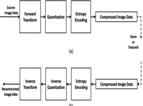
The DCT works by separating images into parts of differing frequencies during a step called quantization where the part of compression actually occurs i.e. less important frequencies are discarded and only the most important frequencies remain that are used to retrieve the image in the decompression process. As a result, reconstructed image contain some blocking effect which can be adjusted during the compression stage by using DWT.
DCT Encoding System
There are four steps in DCT technique to encode or compress the image
Step1. The image is broken into N*N blocks of pixels. Here N may be 4, 8, 16,etc.
Step2. Working from left to right, top to bottom, the DCT is applied to each block.
Step3. Each block’s elements are compressed through quantization means dividing by some specific value. Step4. The array of compressed blocks that constitute the image is stored in a drastically reduced amount of space.
[image:3.595.316.553.561.737.2]So first the whole image is divided into small N*N blocks then DCT is applied on these blocks. After that for reducing the storage space DCT coefficients are quantized through dividing by some value or by quantization matrix. So that large value is become small and it need small size of space. This step is lossy step. So selection of quantization value or quantization matrix is affect the entropy and compression ratio. If we take small value for quantization then we get the better quality or less MSE(Mean Square Error) but less compression ratio. Block size value also affects quality and compression ratio. Simply the higher the block size higher the compression ratio but with loss of more information and quality.
© 2017, IRJET | Impact Factor value: 5.181 | ISO 9001:2008 Certified Journal | Page 194
DCT Decoding SystemDecoding system is the exact reverse process of encoding. There are four steps for getting the original image not exact but identical to original from compressed image.
Step1. Load compressed image from disk Step2. Image is broken into N*N blocks of pixels.
Step3. Each block is de-quantized by applying reverse process of quantization.
Step4. Now apply inverse DCT on each block. And combine these blocks into an image which is identical to the original image.
In this decoding process, we have to keep N’s value same as it used in encoding process.de-quantization process by multiplying with quantization value or quantization matrix. As earlier said that this is lossy technique so output image is not exact copy of original image but it is same as original image. So this process’ efficiency is measure by compression ratio. Compression ratio is defined by ratio of storage bits of original image and storage bits of compressed image.
Fig :
DCT Decoding StrcutureTake summation of both images that is out reconstructed image. Though in DWT, we get very high compression ratio, we lose minimum amount of information. But if we do more than one level then we get more compression ratio but the reconstructed image is not identical to original image. MSE is greater if DWT apply more than one level. In nowadays, this technique is use in JPEG2000 algorithm as one step of its. We think that, we get better result in DWT. But that’s not always true. The better result comes in cost of processing power.
IV. PROPOSED ANALYSIS
Discrete Cosine Transform
In particular, a DCT is a Fourier-related transform similar to the discrete Fourier transform (DFT), but using only real numbers. The DCTs are generally related to Fourier series coefficients of a periodically and
symmetrically extended sequence whereas DFTs are related to Fourier series coefficients of a periodically extended sequence. DCTs are equivalent to DFTs of roughly twice the length, operating on real data with even symmetry, whereas in some variants the input and/or output data are shifted by half a sample. There are eight standard DCT variants, of which four are common.
[image:4.595.361.507.357.460.2]The most common variant of discrete cosine transform is the type-II DCT, which is often called simply "the DCT". Its inverse, the type-III DCT, is correspondingly often called simply "the inverse DCT" or "the IDCT". Two related transforms are the discrete sines transform (DST), which is equivalent to a DFT of real and odd functions, and the modified discrete cosine transforms (MDCT), which is based on a DCT of overlapping data. Multidimensional DCTs (MD DCTs) are developed to extend the concept of DCT on MD Signals. There are several algorithms to compute MD DCT. A new variety of fast algorithms are also developed to reduce the computational complexity of implementing DCT.
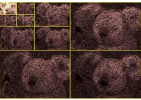
Fig : Three level decomposition for 2D –DWT
Image consists of pixels that are arranged in two dimensional matrixes, each pixel represents the digital equivalent of image intensity. In spatial domain adjacent pixel values are highly correlated and hence redundant. In order to compress images, the seared infancies existing among pixels needs to be eliminated.DWT processor transforms the spatial domain pixels into frequency domain information that are represented in multiple sub-bands, representing different time scale and frequency points. One of the prominent features of JPEG2000 standard, providing it here solutions capability, is the use of the 2D-DWT to convert the image samples into a more compressible form. The JPEG2000 standard proposes a
wavelet transform stages incent offers better
rate/distortion(R/D) performance than the traditional DCT
.
1. Filter coefficient
[image:4.595.37.293.378.502.2]© 2017, IRJET | Impact Factor value: 5.181 | ISO 9001:2008 Certified Journal | Page 195
values, but rather have to be selected carefully In order tolead to basic functions, such as those in, with the necessary properties of compactness (i.e. spatial localization) and orthogonality
gk= (−1)k hn−k−1, k ∈ {0, . . . , n−1},
Where n denotes the length of the filter. For example, for filter lengths 2, 4 and 6:
h = [c0 c1 => g = [c1 –c0] h = [c0 c1 c2 c3] => g = [c3 –c2 c1 –c0] h = [c0 c1 c2 c3 c4 c5] => g = [c5 –c4 c3 –c2 c1 –c0]
The simplest wavelet filter is the Haar filter, where h is given by,
√ √ … (1)
This filter gives rise to basic functions of the type another very popular set of wavelet filters is due to Daubechies. The most compact of these has four coefficients (Daubechies- 4), where h is given by,
√
√ √
√ √
√ √
√ ...(2)
This filter gives rise to basic functions of the type shown in; they will, of course, differ depending on the length of the signal x. Other Daubechies filters of lengthn, n ∈ {6,8, 10 . . .} are also derivable; again, for a discussion and derivation of these filter coefficients
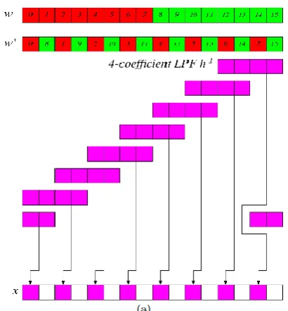
Fig : (a) The inverse low-pass filterh−1is applied in increments of two,
2. Inverse DWT
To understand the procedure for computing the one-dimensional inverse DWT, consider where we illustrate the inverse DWT for a one-level DWT of length 16 (assuming filters of length four). Note that the two filters are now h−1 and g−1where).
hk-1 { | ∈ { ….(3) hk-1 { | ∈ { And g−1 is determined from h−1 using equation
To understand how to compute the one-dimensional inverse DWT for multi-level DWTs, consider first, to compute w2 from w3, the procedure is applied only to values L3 and H3. Second, to compute w1 from w2, the procedure in is applied to valuesL2 and H2. Finally, to compute x from w1, the procedure is applied to all of w1– namely, L1 and H1.
Embedding algorithm for iris image
Input: s1; L;W;X
(s1: watermarking key, L: locations array, W: watermarking text, X: host image)
Output: Y (Y : watermarked image)
1: for i = 1 !size(W) do
2: X8_8(i) = X; fsubdivide the host image (X) into blocks of 8 _ 8 pixelg
3: XDCT(i) = 2D-DCT(X8_8(i)) fCompute the 2D-DCT of each 8 _ 8 block of the hostimageg
4: for each DCT block, generate 4 random numbers r within the range of 1<8 based on the private key s1.
5: if W(i) = 0 then
6: for j = 1 ! 4 do
7. p = r(j) fselect one of the random locationsg 8: exchange DCT coefficients to meet this condition DCT(Lp;1) < DCT(Lp;2) fNow adjust the four values such that their difference becomes larger than the strenghth constant s, thus:g
9: if DCT(Lp;1) <DCT(Lp;2) < s then
10: DCT(Lp;1) = DCT(Lp;1) + s=2
11: DCT(Lp;2) = DCT(Lp;2) � s=2 12: end if
13: end for
14: else if W(i) = 1 then
15: for j = 1 ! 4 do
16. p = r(j) fselect one of the random locationsg 17: exchange DCT coefficients to meet this condition DCT(Lp;1) >= DCT(Lp;2) fNow adjust the three values such that their difference becomes larger than the strength
constant s, thus:g
18: if DCT(Lp;2) - DCT(Lp;1) < s then
19: DCT(Lp;2) = DCT(Lp;2) + s=2
20: DCT(Lp;1) = DCT(Lp;1) � s=2 21: end if
22: end for
23: end if
[image:5.595.67.272.405.626.2]© 2017, IRJET | Impact Factor value: 5.181 | ISO 9001:2008 Certified Journal | Page 196
V. EVALUATION RESULT
[image:6.595.306.560.71.258.2]The major fingerprint biometric security systems bypass that requires creating a proper clone of the finger, IRIS recognition hacks only need in the print out, the researcher claims. "We have managed to fool a commercial system with a printout of an iris image". Tests with different people and can say that an iris image with a diameter down to 75 pixels worked. The print out had to have a resolution of 1200 dpi too, though it’s easy to find printers able to hit that specification, and ideally at least 75 per cent of the iris was visible." So, an attacker willing to carry out this kind of attack just needs a high definition picture of the target person with a bright eyes, and unsurprisingly, there are a vast number of high quality images of some of most powerful personality in the world are available.
Fig : Image of Two Classes of the CASIA V3 Internal IRIS Data base
The file name of each image in CASIA-IrisV1 is unique to each other and denotes some useful properties associated with the image such as session ID, class ID, and image ID etc. The images of CASIA-IrisV1 are stored as: $root path$/XXX/S/XXX_S_Y.bmp XXX: the unique identifier of eye, range from 001 to 108. S: the index of session denotes the first session and the second session. Y: the index of image in the same session. Range from 1 to 3 in the first session, 1 to 4 in the second session.
Therefore XXX_S_Y:bmpmeans the iris image with index Y in session S from eye XXX. The database is released for research and educational purposes. Thus hold no liability for any undesirable consequences of using the database. All rights of the CASIA database are reserved
Fig 5.2: Feature Extraction Roc Curves Validates
The MASEK feature extraction algorithm combined with different classifier kernel functions (linear, or radial basis function (rbf), and polynomial), obtained
[image:6.595.32.281.316.482.2]experimental results showed the best precision with the rbf kernel (100%) and almost catches all the number of positive class even better than results. These figures show that for any given false positive rate, the true positive rate provided that, the test is outstanding. Comparing between the MASEK and Maet, Al. feature extraction algorithms by applying a linear kernel function of the classier.
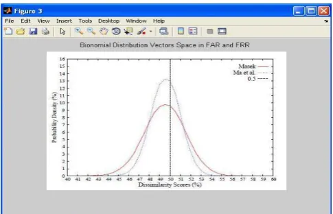
Fig : Binomial Distribution vector space in FAR and FRR
Nevertheless when applying radial basis kernel function with the Embedding with the MASEK feature extraction algorithm, this approach achieved its maximum detect ability rate. It can be concluded that the MASEK using radial basis function with the MASEK feature extraction algorithm offers greater detect ability of the Tilapia species than the Ma et al. feature extraction algorithm.
Conclusion
[image:6.595.314.557.354.510.2]© 2017, IRJET | Impact Factor value: 5.181 | ISO 9001:2008 Certified Journal | Page 197
interchanging four pairs of the DCT middle bandcoefficients. The embedding locations were randomly selected based on a private key. The file name of each image in CASIA-IrisV1 is unique to each other and denotes some useful properties associated with the image such as session ID, class ID, and image ID etc.Feature Extraction Roc Curves Validates MASEK and Maet, Al to obtain the false acceptance rate accurately.Distribution Reliability in Ma and MASEK is compared in the 128 bit blocks, and here it gives the accurate result on MASEK, is not clearly obtained in Ma. And it is concluded that MASEK gives the accurate false acceptance rate for Authentication.
Future Work
Basically it is hard to maintain the originality of the input image is totally leads to distortion problems. So a robust watermarking along with cryptography can be developed which can prevent the image from being hacked as well as distorted. Mostly the file type presently being worked upon i.e. .jpg format should be increased to a lot more .gif, png format. And last but not the least the encryption –decryption techniques should be changed as per emergence of new technologies
REFERENCES
1. P. Stavroulakis and M. Stamp, Handbook of
Information and CommunicationSecurity. Springer, 2010.
2. N. Ratha, J. Connell, and R. Bolle, “An Analysis of
Minutiae MatchingStrength” Springer Berlin
Heidelberg, 2016, vol. 2091, book section 32,pp. 223– 228.
3. K. Martin, L. Haiping, F. M. Bui, K. N. Plataniotis, and D. Hatzinakos,“A biometric encryption system for the self-exclusion scenario of facerecognition,” IEEE Systems Journal, vol. 3, no. 4, pp. 440–450, 2009. 4. A. Jain, A. Ross, and U. Uludag, “Biometric template
security: Challengesand solutions,” in 13th European Signal Processing Conference,EUSIPCO05, 2015, pp. 1– 4.
5. J. Daugman, “How iris recognition works,” IEEE
Transactions onCircuits and Systems for Video Technology, vol. 14, no. 1, pp. 21–30,2004.
6. S. Venugopalan and M. Savvides, “How to generate
spoofed irises froman iris code template,” IEEE Transactions on Information Forensics andSecurity, vol. 6, no. 2, pp. 385–395, 2011.
7. J. Galbally, A. Ross, M. Gomez-Barrero, J. Fierrez, and J. Ortega-Garcia, “Iris image reconstruction from binary templates: An efficientprobabilistic approach based on genetic algorithms,” Computer Visionand Image Understanding, vol. 117, no. 10, pp. 1512–1525, 2013.
8. K. Park, D. Jeong, B. Kang and E. Lee, “A Study on Iris
FeatureWatermarking on Face Data”Springer Berlin
Heidelberg, 2007, vol.4432, book section 47,pp. 415– 423.
9. A. Hassanien, A. Abraham, and C. Grosan, “Spiking
neural network andwavelets for hiding iris data in digital images,” Soft Computing, vol. 13,no. 4, pp. 401– 416, 2009.
10. S. Majumder, K. J. Devi, and S. K. Sarkar, “Singular value decompositionand wavelet-based iris biometric watermarking,” IET Biometrics,vol. 2, no. 1, pp. 21–27, 2013.
11. M. Paunwala and S. Patnaik, “Biometric template
protection with DCTbasedwatermarking,” Machine Vision and Applications, vol. 25, no. 1,pp. 263–275, 2014.
12. M. A. M. Abdullah, S. S. Dlay, and W. L. Woo, “Securing
irisimages with a robust watermarking algorithm based on Discrete CosineTransform,” in Proceedings of the 10th International Conference onComputer Vision Theory and Applications, vol. 3, 2015, pp. 108– 114.
13. F. Hao, R. Anderson, and J. Daugman, “Combining
crypto with biometricseffectively,” IEEE Transactions on Computers, vol. 55, no. 9, pp.1081–1088, 2015. 14. J. Bringer, H. Chabanne, G. Cohen, B. Kindarji, and G.