© 2016, IRJET | Impact Factor value: 4.45 | ISO 9001:2008 Certified Journal | Page 76
Effectiveness Evaluation for VHF Radar Jammer
Dr.T.Pandikumar
1, Tsegay Tesfay
21Ph.D. Department of Computer & IT, College of Engineering, Defence University, Ethiopia 2M.Tech. Department of Computer & IT, College of Engineering, Defence University, Ethiopia
---***---Abstract -
The Travelling Wave Tube (TWT) radar jammer developed an electronic countermeasure module to allow hobbyists and educators to demonstrate and innovate methods of defeating tactical radar. The system consisted of radar and an ECM module. The radar can image a 2D field of view that includes the ECM module. The module can detect that it is being imaged, collect data about the radar and classify it, and then attempt to jam the radar using techniques appropriate for the type of radar identified. The radar was built using a modified version of a design originally pioneered at MIT. To reduce cost, it outputs data through an audio jack, eliminating the requirement of an external ADC. Instead, this data is captured directly from a PC sound card and analyzed using MATLAB or Octave. The ECM module is designed around a USRP, an inexpensive software defined radio that can be programmed using the open source framework GNU Radio. The frequency of operation is 2.4 GHz, so standard directional Wi-Fi antennas can be used. The demonstration of this project involved imaging a 2D area with radar and showing that by activating the ECM module, false targets can be created. Using a simple object tracker, the radar tracked incorrect information about the real target as well as incorrect information about other false targets. Current countermeasure units cost at least a million dollars, require high level security clearances, and are unavailable to the majority of people. The ECM teams’ module has 50% of the functionality of modern countermeasure modules at 0.1% of the cost.Key Words: TWT, ECM, Radar, Jammer, EM, Receiver, RF
1. INTRODUCTION
1.1 Background
Travelling Wave Tubes Radar jammers(TWTs) are amplifiers used in satellite communications (e.g. cellular phones, television broadcast, or scientific satellites) or electronic countermeasures (e.g. radar jamming). The possibility of several simultaneous communications channels in one TWT is attractive since it increases communication density " for a given satellite, or, alternatively, reduces satellite payload. When a standard TWT is used with multiple simultaneous communications channels (multi tone
drive) there are unwanted consequences, most notably distortion of the output.
This thesis investigates the modeling of a Traveling Wave Tube (TWT) under multi tone drive. Multi tone drive means that the spectrum of the input signal, or drive signal, fed to the amplifier has several distinct tones, or carriers, each of which is intended to transmit information not related to the information on the other carriers.
For even moderate levels of drive signals the spectrum on the output of the amplifier contains frequency content not found in the input, i.e. the output is not just a scaled version of the input. This distortion of the input signal makes the subsequent decoding of the information on the carriers difficult. We study the physics, modeling, and analysis of the TWT with the aim of improving the device performance.
1.1.1 The Traveling Wave Tube
The Traveling Wave Tube is a device which is used for the amplification of coherent electromagnetic waves, typically in the microwave (1 − 100 GHz) range. The free energy required for the amplification of the wave comes from DC energy stored in an electron beam that is passed in near proximity to the electromagnetic (EM) wave. If the electron beam and the EM wave have nearly the same velocities, energy in the beam is given to the wave which manifests in wave amplitude growth; the growth is due to an inherent instability in the beam-wave system.
© 2016, IRJET | Impact Factor value: 4.45 | ISO 9001:2008 Certified Journal | Page 77 2. EFFECTIVENESS EVALUATION
2.1 Eeffectiveness evaluation of VHF Radar Jammer
Electronic warfare is any military action involving the use of the EM spectrum to include directed energy (DE) to control the EM spectrum or to attack an enemy. This is not limited to radio or radar frequencies but includes IR, visible, ultraviolet, and other less used portions of the EM spectrum. This includes self-protection, standoff, and escort jamming, and anti-radiation attacks. EW is a specialized tool that enhances many air and space functions at multiple levels of conflict.
The purpose of EW is to deny the opponent an advantage in the EM spectrum and ensure friendly unimpeded access to the EM spectrum portion of the information environment. EW can be applied from air, sea, land, and space by manned and unmanned systems. EW is employed to support military operations involving various levels of detection, denial, deception, disruption, degradation, protection, and destruction.
This thesis paper presents an experimental investigation of the nonlinear behavior of travelling wave tube amplifier. Preliminary computational modeling results are also shown using the numerical suite. This understanding is crucial to develop and explore linearization techniques for the TWT. In particular, signal injection schemes are investigated for suppressing nonlinear distortion products eg. Second-harmonic suppression by second-harmonic injection and third-order inter modulation suppression by injection of second-harmonic or/and third-order inter modulation frequency. It is shown that by injecting a small amount (15 dB or less) of properly phased harmonic or inter mod signal at the input, the TWT nonlinearity can be utilized to suppress the distortion signal produced naturally at the output. Experimental ix evidence is provided to support a new understanding of the physical mechanism responsible for suppression by signal injection. The concepts examined and experimentally measured open the possibility to develop several related schemes for distortion suppression in TWT amplifiers and have an enormous potential to enhance efficiency, bandwidth and data-rates for satellite communication and electronic countermeasure applications.
2.2 Simplified Block Diagram of a Jammer
The Figure 1 shows a block diagram of a jammer. The RF-carrier comes in from the antenna and is applied to a filter. The output of the filter is only the frequencies of the desired frequency-band. These frequencies are applied to the mixer stage. The mixer also receives an input from the local oscillator. These two signals are beat together to obtain the IF through the process of heterodyning. The IF-carrier is applied to the IF-amplifier. The amplified IF is then sent to the Match filter for optimal detector. The output of the detector analyzed at radar signal parameter measurement. After decision (at Command and Control circuit) this signal can be used as a n input for jammer transmitter.
[image:2.595.308.562.617.742.2]A signal classifier performs measurements on an IF signal and determines from these measurements the nature of the modulation, if any, appearing on a received high frequency radar signal. The classifier distinguishes modulation type, un modulated carrier and noise in short signal classification is used to detection, pattern recognition and decision making system Parameter Measured by Jammer System: Each instantaneous signal intercepted by the jammer system must be characterized by a set of parameters. This provides the information required to associate a set of signals belonging to a particular emitter and to identify that emitter among other emitters whose signals have been intercepted. The parameters generally measured by the jammer system are carrier (RF) frequency, pulse amplitude (PA), pulse width (PW), and angle of arrival (AOA).Once a signal is isolated, another set of signal parameters associated with the emitter can be determined which include the PRF, antenna scan rate or type, and range.
© 2016, IRJET | Impact Factor value: 4.45 | ISO 9001:2008 Certified Journal | Page 78 If a threat signal is identified, a jamming signal is
created at DDS (direct digital synthesizer) and the jammer modulator can mix this signal and jammer noise signal (Gaussian). The desired output power can be provide at power amplifier (it provides 50-watt for Stand-off, and 6.3-watt for stand-in jammer. The entire desired jammer signal is radiated toward the victim radar.
Coordination of this processing section is facilitated through command and control element consisting of a finite state machine and a number of control ports. This control element typically maintains the database, which has predefined the necessary data before Deployment, and is used to dynamically load and unload jamming modulation schemes.
2.3 Duplexers
Most radar systems (including missile seekers) use one antenna to perform the transmit and receive functions. Since most radar utilizes very high power transmitters and very sensitive receivers, a radar using only one antenna requires a “front end” configuration which will alternately “connect” and “disconnect” the transmitter and receiver from the antenna on a pulse to pulse basis. This is the function of the duplexer. A duplexer, in effect, acts as a very fast, self-actuating SPDT or transmit - receive switch. The duplexer must be able to perform the following main functions:
• Connect the transmitter to the antenna (and disconnect the receiver) during the sending period. • Connect the receiver to the antenna (and disconnect the transmitter) during the receive period.
• Provide for adequate isolation between the receiver and transmitter at all times.
Basic components of TWT Radar Jammer
I. Receiver which is used to receive any EMS from the space and amplify it.
II. Amplifier used to amplify the signal which is received from the receiver
III. Switch to transmit and receive a signal from receiver and transmitting antenna
IV. Antenna to receive and transmit any signal V. Power supply to generate power to the
station VI. Application
VII. Transmission media
2.4 ES RECEIVER CHALLENGES
To detect LPI radar signals, ES receivers have to overcome three main difficulties. These are:
i. Processing gain of the LPI radar ii. High sensitivity requirement iii. LPI radar’s coherent integration
2.5 ES RECEIVERS FOR LPI RADAR DETECTION
Some wide-open ES receivers such as the Instantaneous Frequency Measurement (IFM) and Crystal Video Receivers (CVR) work well in a low density signal environment where the pulses are short in duration. However, they are susceptible to interference in a dense signal environment where radar pulses overlap in time. This problem has become more severe with the introduction of pulse compression waveforms and pulse Doppler radars with their higher duty cycles. The problem associated with signal overlap may become worse with LPI signals which are expected to maintain even higher duty cycles. On the other hand, LPI signals are expected to be of much lower in peak power, and thus those LPI radars which are far away will not affect the performance of the ES receiver. However, there are likely to be “friendly” LPI radars on the same platform or nearby which will cause interference. As a result, with the proliferation of pulse compression and LPI signals, current wide-open IFM and crystal video receivers will be more susceptible to interference and thus are poor candidates for future ES receiver systems. In addition, they do not have the sensitivity for the detection of current and projected LPI signals. With a scenario involving FMCW LPI radar and an IFM receiver, the effects of processing gain and sensitivity on detection ranges can be seen. In the scenario the range at which 100% probability of intercept can be achieved against the main beam of the radar will be taken as the baseline measure of performance (MOP).
2.6 Basic TWT
© 2016, IRJET | Impact Factor value: 4.45 | ISO 9001:2008 Certified Journal | Page 79 electrons strike the "collector", which returns them
to the circuit.
Wrapped around the inside of the tube, just outside the beam path, is a helix of wire, typically oxygen-free copper. The RF signal to be amplified is fed into the helix at a point near the emitter end of the tube. The signal is normally fed into the helix via a waveguide or electromagnetic coil placed at one end, forming a one-way signal path, a directional coupler.
By controlling the accelerating voltage, the speed of the electrons flowing down the tube is set to be similar to the speed of the RF signal running down the helix. The signal in the wire causes a magnetic field to be induced in the center of the helix, where the electrons are flowing. Depending on the phase of the signal, the electrons will either be sped up or slowed down as they pass the windings. This causes the electron beam to "bunch up", known technically as "velocity modulation". The resulting pattern of electron density in the beam is an analog of the original RF signal. Because the beam is passing the helix as it travels, and that signal varies, it causes induction in the helix, amplifying the original signal. By the time it reaches the other end of the tube, this process has had time to deposit considerable energy back into the helix. A second directional coupler, positioned near the collector, receives an amplified version of the input signal from the far end of the RF circuit. Attenuators placed along the RF circuit prevent the reflected wave from traveling back to the cathode. Higher powered Helix TWTs usually contain beryllium oxide ceramic as both a helix support rod and in some cases, as an electron collector for the TWT because of its special electrical, mechanical, and thermal properties.
These modes have electric field components along the axis of the helix and axial phase velocities close to the electron beam velocity (approximately the velocity of light multiplied by the tangent of the helix pitch angle). They can be excited by an antenna moving through a cylinder slot and capacitive coupled to the helix in the frequency range from 5 to 95 MHz’s. The SWS is long enough to allow non-linear processes to develop, such as trapping of the beam in the potential troughs of a single wave. Moreover the electron beam density nb is chosen weak enough to ensure that the beam induces no wave growth and the beam electrons can be
considered as test electrons. Finally the cumulative changes of the electron beam distribution are measured velocity analyser at the end of the interaction region. A small fraction (0.5 %) of the electrons passes through a hole in the centre of the front collector, and is slowed down by three retarding electrodes. By operating a selection of electrons through the use of the drift velocity caused by an electric field perpendicular to the magnetic field, the direct measurement of the current collected behind a tiny off-axis hole gives the time averaged beam axial energy distribution with an unprecedented resolution.
2.7 Jamming
Jamming is the intentional emission of radio frequency signals to interfere with the operation of a radar or communication radio by saturating its receiver with noise or false information.
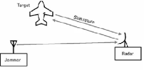
Figure 2 shows the radar-jamming concept. The jammer places a signal into the radar receiver that interferes with the reception or processing of the reflected signals returning from the target. For biostatic radar, you need to put the jamming signal into the receiver location .
Figure 2: Radar-Jamming Geometry
Jamming can be classify by type of threat signal (radar versus communication), by jamming geometry (standoff versus self-protection), and by jamming technique (cover versus deceptive versus decoy). While it is somewhat controversial to include decoys as a type of jamming, they act a lot like jammers and their performance is calculated using some of the same equations.
2.8 Radar Jamming
[image:4.595.310.558.446.566.2]© 2016, IRJET | Impact Factor value: 4.45 | ISO 9001:2008 Certified Journal | Page 80 power of the skin return in the radar receiver.
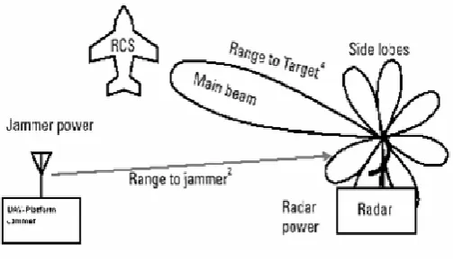
[image:5.595.311.558.154.281.2]There are several complicating factors to consider. First, we must consider the radar antenna directivity. The radar antenna is pointed at the target, so the skin return is increased twice by the gain of the antenna (once during transmission and once during reception). The transmitted jamming signal is increased by the jammer antenna gain (not the radar antenna gain) and is increased by receiving gain of the radar antenna only if the jammer is located on the target. Otherwise, the jammer must enter the radar antenna through its side lobes, which have much less antenna gain. Thus, as summarized in the J/S for radar jamming is a function of the fourth power of the distance to the target divided by the square of the distance to the jammer. It is also a function of the radiated jammer power to the radiated radar power and the ratio of the radar side lobe power to main beam power. The final factor is the RCS of the target. All else being the same, the smaller the RCS, the larger the J/S.
Figure 3: Radar-Jamming J/S Factors
2.9 Jamming Tactics: Three Standard Tactics are used
A. Stand-off
B. Stand-in Jamming C. Self-screen Jamming
Support ECM is ECM radiated from one platform and is used to protect other platforms. Figure 4 illustrates two cases of support jamming: stand-off jamming (SOJ) and stand-in jamming (SIJ). For SOJ the support jamming platform is maintaining an orbit at a long range from the radar – usually beyond weapons range (Usually greater than 60Km). For SIJ, a remotely piloted vehicle is
[image:5.595.40.292.394.540.2]orbiting very close to the victim radar, for this study the effect of jamming from 130 Km to 50 Km from the victim radar, including crossover range have been described .
Figure 2: Stand-off and Stand-in jamming geometry
3. IMPLEMENTATION
3.1 Software SimulationIt is difficult to find free military simulators in order to solve such kinds of problems we have used a military simulation tool which is prepared by Russian experts to apply to this thesis work on TWT Radar Jammer. The tool is based with batch files, which are also called batch programs or scripts; you can simplify routine or repetitive tasks. A batch file is an unformatted text file that contains one or more commands and has a .bat or .cmd file name extension. When we type the file name at the command prompt, Cmd.exe runs the commands sequentially as they appear in the file. We can include any command in a batch file. Certain commands, such as for, go to, and if, enable us to do conditional processing of the commands in the batch file. For example, the ‘if’ command carries out a command based on the results of a condition. Other commands allow us to control input and output and call other batch files.
The standard error codes that most applications return are 0 if no error occurred and 1 (or higher value) if an error occurred. We have tried to discuss the theoretical background of TWTs and the its method of implementations. We have used in order to see the out puts of the result of TWT radar jammer. We have not right to modify simulation tool as well as its parameters.
3.2 The platform
© 2016, IRJET | Impact Factor value: 4.45 | ISO 9001:2008 Certified Journal | Page 81 choosing this specific Operating system is for
research work is XP an Operating System (OS) dictates how all the parts (software and hardware resources) of your computer work together and how specific tasks (i.e., displaying and saving information) are to be performed.
Windows XP is built primarily on Windows 2000 technology which includes the best attributes of previous Windows versions. People who already know and have used previous versions of Windows should have no problems using Windows XP. One major difference will be in the logging in and logging out procedures. Windows XP offers several benefits over other versions, namely, its built-in file encryption and password control capabilities provide basic data and access security, increased reliability and performance ability, friendly graphical user interface (GUI), and its Web communication features. Windows XP's desktop is graphical which allows the user to click on pictures (or icons) to launch applications, open files and folders, connect to a network, and perform many other functions.
Users should find that Windows XP is more efficient and customizable than previous versions and other platforms. The Start button on the bottom left corner of the screen allows easy access to just about everything in the system. The Start button is used to initiate applications, opens or search for documents, adjusts settings, activates the Help Support system, manages files, and maintains the entire system to meet your specific needs.
3.3 Inputs for the simulator i. Operating frequency ii. Time duration iii. Pulse width iv. Scan rate
v. Frequency repetition
Based on the inputs which are listed above and based on the radar and radar jammer equation it calculates the range of radar without jamming and the range of the radar with jamming. We have found two simulators which are used to simulate this thesis mat-lab and AMR (Automatic Model of Relocation). But we used mat-lab in order to show clearly radar jammer and to know its effectiveness related to any signal.
But AMR a tool which is made up of Russian experts which is used calculate the killing probability of the missile without jamming and with jamming. And also to show the burn through range of the radar so the pilot can determine his rout in order to destroy any target.
4. SIMULATION AND ANALYSIS
RJARS (RAND's version of the Jamming Aircraft and Radar Simulation) is a many-on-many computer simulation involving aircraft, radars, IR and optical systems, jamming systems, offensive and defensive missiles, and a command, control, and communications system for the defense. The simulation can handle hundreds of aircraft and radars. Terrain masking, clutter, and multipath are included. It is an extensive development by RAND of the computer program JARS (Jamming Aircraft and Radar Simulation), which originated at the Johns Hopkins University Applied Physics Laboratory. RJARS has been designed to treat sortie operations and evaluate jamming effectiveness and mission attrition at a level of detail that includes reasonable refinements of equipment operation without excessive calculation complexity. At RAND, RJARS operates in conjunction with the Army's JANUS ground combat model, the CAGIS (Cartographic Analysis and Geographic Information System) terrain model, and several flight planners. All operations of RJARS have been programmed both for independent operation and for use of these external programs.
The jamming power is generally greater than the target signal power. In other words, the ratio S/J is less than unity. However, as the target becomes closer to the radar, there will be a certain range such that the ratio S/J is equal to unity. This range is known as the cross-over range. The range window where the ratio S/J is sufficiently larger than unity is denoted as the detection range. In order to compute the crossover range Rco, set S/J to unity in Eq. (4.21) and solve for range. It follows that If the calculated value exceeds the random value, a kill takes place.
4. 1 Repeater jamming
© 2016, IRJET | Impact Factor value: 4.45 | ISO 9001:2008 Certified Journal | Page 82
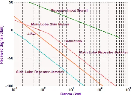
Figure 3: Repeater Jamming
The crossover point where J = S could be the burn-through range, but it usually isn't because normally J/S > 0 dB to be effective due to the task of differentiating the signal from the jamming noise floor.
Radar can be designed with higher power than the necessary power for earlier burn-through on jamming targets. Naturally that would also have the added advantage of earlier detection of non-jamming targets as well. Since the jammer on the target amplifies the received radar signal before transmitting it back to the radar, both J and S experience the two way range loss. Normally, the constant gain (linear) region of a repeater jammer occurs only at large distances from the radar and the constant power (saturated) region is reached rapidly as the target approaches the radar. Once the jammer output reaches maximum power, that power is constant and the jamming slope changes since it is only a function of one way space loss and the J/S the cross over range is less than 0.2 Km, which is better than noise jamming, however implementation of repeater jammer is not difficult for ground based jammer. The jammer flow chart for the simulation is helpful to summarize the analysis and it is given below.
5. CONCLUSION AND FUTURE WORK
Successfully denying the use of the radar spectrum is the purpose of Electronic attack EW. It depends on many factors, including the distance between the radar and the jammer, the ERP from the jammer relative to the ERP of the radar transmitter and receiver. Because the Predator is unmanned it is suitable for deployment in "moderate risk areas", i.e.
unsecured air space. The Predator system was designed to provide constant intelligence, surveillance, reconnaissance for strategic and tactical forces. In this thesis Ground based jammer is used for radar jamming purposes.
In this thesis interception of P-18 radars’ signal by the jammer-receivers have been described. The jammer receiver allows the threat to be identified and the parameters set to be updated with the latest information relevant to the specific emitter which is to be jammed (such as frequency, pulse width). The command and control system of the jammer can be decided by using this parameter (jam or no jam). The jammer waveform is then synthesized at DDS and used to generate multiple synchronized random jamming pulses that are received through the radar antenna.
Stand-in jamming is more effective than stand-off jamming for UAV-Platform by decreasing the jammer transmitted power and by attacking the radar main lob. In addition to this the jammer performance can be increased by using pulse integration technique, in this case the pulse integration loss must be taken into consideration (i.e. if the number of pulse-integration is increased then the pulse-integration loss also increases). So TWT jammer is more effective than all methods of jammers.
The application of this jamming is to protect our country from enemy attack with endangering human pilot’s life. In Ethiopia geographical nature, Ground based jammer is substantially less vulnerable and more survivable. In addition to this economic viability is also worth to consider.
6. REFERENCES
[1] Michael O.Kolewole, PhD, “Radar systems, peak Detection and Tracking” Amsterdam, Liuacre, Houle, Jordan Hill, 2002, P: 64, 66,107-108,111-120,126-132,279,281.
[2] Merrill I. Skolnik, “Introduction to Radar system”, second ed. United State, Mc Graw-Hill, lnc, 980. P: 7, 19, 23, 47-56,152,226,227,460.
© 2016, IRJET | Impact Factor value: 4.45 | ISO 9001:2008 Certified Journal | Page 83 [4] Richard I. Wiegand, “Radar Electronic Countermeasures
System Design”, London, Artech House, Inc, 1991, P: 11, 18, 47, 183.
[5] Rowun Gilmore, “Practical RF circuit Design for Modern Wireless System”, Volume 1,Boston, Artech House, Inc 2003 P: 81-85.
[6] Bernard Sklar, “Digital Communication Fundamental and Applications”, Second Edition, New Jersey, P: 169,171,178,251,253,254.
[7] W.Alan Davis, Krisha Agarway,” Radio frequency Circuit Design”, New York/Tronto,John Wily and sons, inc. 2001, P: 121,168,222.
[8] David L. Adamy, “Introduction to Electronic warfare modeling and simulation” ,Canton Street, Artch House, 2003, P: 9,10,14,16.
[9] Mugu, “Electronic warfare and Radar systems Engineering Handbook”, Washington D.C, April 1999, section 4-4.5, 4-7.5, 4-.1, 4-10.1.
[10] James D.Taylor,”Ultra-wideband Radar technology,” Florida, CRC Press, 2000, P: 133.