© 2018, IRJET | Impact Factor value: 6.171 | ISO 9001:2008 Certified Journal | Page 3497
EFFECT OF SOIL STRUCTURE INTERACTION ON SEISMIC BEHAVIOR OF
MULTI-STOREY [G+5] BUILDING WITH DIFFERENT TYPES OF SLABS
Manchem Lakshmi Prakasam
1, V. Siva Rama Raju
21
M.Tech scholar, Department of civil Engineering, S.R.K.R Engineering College, Bhimavaram, India.
2Professor, Department of civil Engineering, S.R.K.R Engineering College, Bhimavaram, India.
---***---Abstract
-
The aim of this study is to know the seismicbehavior of multi-storey [G+5] structure with different types of slab systems and how soil structure effects that behavior. This paper deals with four types of slab systems, they are Flat plate system, Flat slab with drop system, Grid slab system and Dia-Grid slab system. The seismic behavior of these slab systems are studied by modeling a G+5 building. This analytical study can be done by ETABS software. This study comprises of comparison of story displacement, base shear, bending moments and axial forces of columns of the building and how much amount of concrete and steel required for each floor in different slab systems.
Key Words: Equivalent linear static analysis or seismic coefficient method, soil structure interaction, storey displacement, base shear, axial force, bending moment, ETABS.
1. INTRODUCTION
Natural disasters involves in the development of civil engineering structures. Earthquake is one of the natural disaster which creates huge destruction of structures. There are few methods which are used for earth quake analysis. Earthquake creates huge amount of lateral loads which destructs the structures in higher degree. Due to rapid population growth there is necessary arises for construction of multi storey structures. Buildings which are designed for static loads are not capable to withstand against earthquake loads because they acts laterally. So we have to consider seismic loads while designing of structures. Earthquake loads creates huge amount of base shear so columns faces much amount of bending moments. Structures fail suddenly or number of cracks appears on structural components this leads to loss of life of people and/or economy.
1.1 Soil structure interaction
A study of recent earthquakes has indicated that understanding the relationship between the period of vibration of structures and period of the supporting soil is profoundly important for determining the seismic response of the structure. The pattern of structural damage is directly related to the period of vibration of soil alluvium overlying the bedrock, which in turn is directly related to the period of the soil.
2. OBJECTIVES
1) storey structure with four types of slab systems and how soil profile effects the seismic behaviour. Here
these four models first analysed with fixed supports and later these are compared with spring supports.
2) To study the seismic performance of flat slab, flat slab with drop panel, grid slab and dia-grid slab on medium soil and in seismic zone V.
3) To study the Seismic performance by comparing base shear, storey displacement and column axial forces and bending moments of the building.
4) To perform seismic analysis using “seismic coefficient method” to find base shear of the building and is compare with manual calculation.
5) To develop models and to analyze these models using ETABS 2015 software.
6) To compare how much quantity of steel and concrete required per slab.
7)
To find size of footings using “ TERZAGHI’S BEARING CAPACITY ” formula for shallow square footing.3. METHODOLOGY
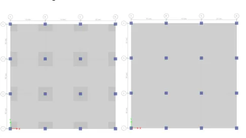
3.1 ModelingA regular G+5 multi-storey structures with four different types of slabs are modeled through ETABS software.
3.2 Description of models
[image:1.595.309.552.584.721.2]
© 2018, IRJET | Impact Factor value: 6.171 | ISO 9001:2008 Certified Journal | Page 3498
Fig-3 : Grid slab system. Fig-4 : Dia-Grid slab system.
3.3 Idealization of structure
To study the dynamic behavior of building structure with soil structure interaction. Here 3 bay x 3 bay five storey building frame with each 10 m x 10 m panel size. This frame is located on isolated footings. The height of each storey is taken as 3.5 m and plinth level is at 1 m above from ground level and 2.5 m above from footing bottom. For all buildings columns of size 900 m x 900 m are considered. Type II soil and seismic zone V is considered. For model (a), thickness of slab is considered as 380 mm. For model (b), 320 mm thick slab and 420 mm thick drop of 4mx4m size is considered. For model (c), 100 mm thick slab, 400x600 mm primary beams and 200x400 mm secondary beams with spacing 2 m are considered. For model (d), 100 mm thick slab, 400x700 mm primary beams and 200x400 mm secondary beams with spacing 2 m are considered. These section sizes are found through design as per IS 456-2000. Importance factor is 1. Live load is taken as 3 KN/m2, floor finish load as 1 KN/m2, wall load as 1.5 KN/m2. Isolated sloped square footings of base sizes 2.6m x 2.6m, 3.2m x 3.2m and 4.2m x 4.2m with edge thickness 200 mm are considered. M30 grade of concrete and Fe415 steel is considered.
3.4 Idealization of soil
Medium soil with standard penetration number N = 10 is considered. Cohesion of soil C = 15 KN/m2, unit weight of soil Г = 20 KN/m2, depth of footing Df = 1.5 m.
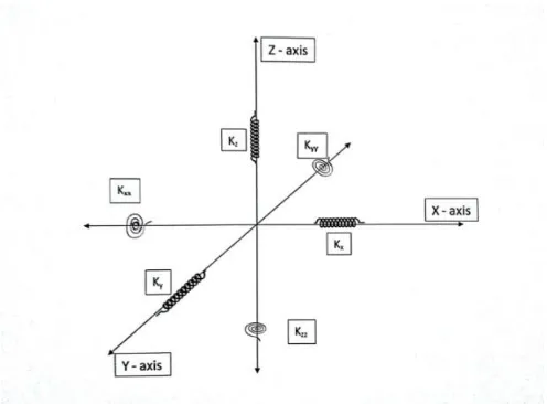
Flexibility of soil medium below foundation may appreciably alter the natural periods of any building. It usually causes to elongate time period of structure. Generally effect of soil profile reduces while considering soft soils to hard. The flexibility of soil is usually modeled by inserting springs between the foundation member and soil medium. While modeling, the number of degree of freedom should be selected carefully considering the objective of the analysis. During earthquake a rigid base may be subjected to a displacement in six degrees of freedom, and therefore resistance of soil can be expressed by the six corresponding resultant force components. Hence to make the analysis most general, translations of foundation in two mutually perpendicular principle horizontal directions and vertical direction as well as rotation of the same about these three directions are considered in this study. In this project, for
isolated footing below each column, three translation springs along two horizontal and one vertical axis, together with three rotational springs about those mutually perpendicular axes, have been attached to simulate the effect of soil flexibility.
Idealization arrangement at a typical column square foundation strip and equivalent soil spring junction as shown below
Fig 5: Idealization arrangement at a typical column square foundation strip and equivalent soil spring junction.
[image:2.595.37.271.63.197.2]GAZETAS (1991); MYLONAKIS et al (2006) gave some formulas as given below
Table 1: Stiffness of rigid footings in respective degrees of freedom.
Translation along
Z-axis Kz = [ 0.73 + 1.54(B/L) 0.75 ]
Translation along
Y-axis Ky = 2 + 2.5(B/L) 0.85 ]
Translation along
X-axis Kx = Ky – GL( 1 – B/L ) Torsion about Z-axis Kzz = GJt0.75[ 4+ 11( 1-B/L )10 ] Rocking about Y-axis Kyy = ( Ix )0.75[ 3(L/B)0.15 ]
Rocking about X-axis Kxx = ( Ix )0.75(L/B)0.25[ 2.4 + 0.5(B/L) ]
[image:2.595.310.558.189.372.2]© 2018, IRJET | Impact Factor value: 6.171 | ISO 9001:2008 Certified Journal | Page 3499
Table 2 : Embedment correction factor for stiffness of rigid footings.
Translation along
Z-axis η z = [ 1 + (1 + 1.3B/L) ][ 1 + 0.2( )2/3 ]
Translation along
Y-axis η y = [ 1 + 0.15 ][ 1 + 0.52( ) 0.4 ]
Translation along
X-axis η x = Same equation as for η y, but A term changes for B ≠ L Torsion about Z- axis η zz = 1+ 1.4( 1 + B/L )(d/B)0.9 Rocking about Y-axis η yy = 1 + 0.92(d/B)0.6[ 1.5 +
(d/D)1.9(B/L)-0.6 ]
Rocking about X-axis η xx = 1+ 1.26(d/B)[ 1+ (d/B)(d/D) -0.2 ]
Where “d” is height of effective side wall contact, “Z” is depth to centroid of effective side wall contact, “A” is side wall solid contact area for constant effective contact height “d” along perimeter.
For each degree of freedom calculate Kemb = ηK
Correlated formula for Shear wave velocity
Vs=50N0.41 m/sec Where “N” is standard penetration number and for medium soils, it’s value = 10
Shear modulus Gmax = Vs2xρs due to ground acceleration there are is some reduction occurs for maximum shear modulus and the considered reduction factor for medium soils is = 0.75
Where ρs = density of soil = 2000 kg/m3
4. RESULTS AND DISCUSSIONS
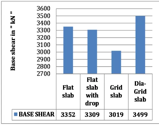
4.1 Base shearIt is the design lateral force at all the levels above storey under consideration. A bar graph is plotted for base shear as shown below. Here all models are regular, so base shear and storey displacements in X and Y directions are same.
Chart 1 : Base shear values for fixed models.
Chart 2 : Base shear values for spring models.
Table 3 : Base shear values for all models.
Model
Base shear in“ kN ” Percentage reduction in base shear ( % ) Fixed model Spring
model
Flat slab 3642 3352 7.96
Flat slab with
drop 3611 3309 8.36
Grid slab 3295 3019 8.38
Dia-Grid slab 3871 3499 9.61
4.2 Storey displacements
[image:3.595.307.564.565.682.2]© 2018, IRJET | Impact Factor value: 6.171 | ISO 9001:2008 Certified Journal | Page 3500 0 10 20 30 40 50 b ase p lin th sto re y 1 sto re y 2 stor ey 3 sto re y 4 sto re y 5 la ter al d isp la cem ent in " m m " Flat slab
Flat slab with drop
Grid slab
Dia-Grid slab
Graph 1 : storey displacements for fixed models.
0 10 20 30 40 50 60 ba se pl int h st or e y 1 st or e y 2 st or e y 3 st or e y 4 st or e y 5 la te ra l d is p la ce m e n t in " m m " Flat slab
Flat slab with drop
Grid slab
Dia-Grid slab
Graph 2 : storey displacements for spring models.
Table 4 : Storey displacements values for all models.
Flat slab in “mm”
Flat slab with
drop in “mm” Grid slab in “mm” Dia-Grid slab in “mm”
Fixed Spring Fixed Spring Fixed Spring Fixed Spring
Storey 5 45 48 41 43 37 39 31 34 Storey 4 38 40 34 36 31 33 27 30
Storey 3 28 31 26 28 24 26 21 24
Storey 2 18 21 17 19 15 18 14 17
Storey 1 9 11 8 11 7 10 7 10
Plinth 2 4 2 4 2 4 2 4
Base 0 1 0 1 0 1 0 1
Table 5 : Percentage change in storey displacements.
Model Flat
slab Flat slab with drop Grid slab Dia-Grid slab
Percentage increase in max storey
displacement ( % ) 6.67 4.88 5.41 9.68
4.3 Axial force and bending moment for columns
Table 6 : Axial force and Bending moment for corner columns.
Model
Axial force in “ kN ”
Bending moment in “ kN-m ”
Fixed
model Spring model Fixed model Spring model
Flat slab 3019 3282 937 432
Flat slab with drop 2676 2910 897 409
Grid slab 2937 3121 856 379
Dia-Grid slab 3075 3320 912 395
Table 7 : percentage change in Axial force and Bending moment for corner columns.
Model Percentage increase
in axial force ( % ) Percentage decrease in bending moment ( % )
Flat slab 8.71 53.9
Flat slab with drop panel
8.74 54.4
Grid slab 6.26 55.72
[image:4.595.41.287.281.455.2]Dia-Grid slab 7.97 56.67
Table 8 : Axial force and Bending moment for edge columns.
Model
Axial force in “ kN ”
Bending moment in “ kN-m ”
Fixed
model Spring model Fixed model Spring model
Flat slab 6171 6433 1018 617
Flat slab with
drop 5440 5670 984 591
Grid slab 5050 5089 888 538
Dia-Grid slab 5292 5381 947 564
Table 9 : percentage change in Axial force and Bending moment for edge columns.
Model
Percentage increase in axial force
( % )
Flat slab 4.25 39.39
Flat slab with
drop panel 4.23 39.94
Grid slab 0.77 39.41
Dia-Grid slab 1.68 40.44
© 2018, IRJET | Impact Factor value: 6.171 | ISO 9001:2008 Certified Journal | Page 3501
Table 10 : Axial force and Bending moment for inner columns.
Model
Axial force in “ kN ”
Bending moment in “ kN-m ”
Fixed
model Spring model Fixed model Spring model
Flat slab 13382 12595 1039 914
Flat slab with drop 11847 11152 1001 873
Grid slab 9052 8789 893 787
Dia-Grid slab 9417 9151 952 828
Table 11 : percentage change in Axial force and Bending moment for inner columns.
Model Percentage decrease
in axial force ( % ) Percentage decrease in bending moment ( % )
Flat slab 5.88 12.03
Flat slab with drop panel
5.87 12.79
Grid slab 2.91 11.87
Dia-Grid slab 3.64 13.03
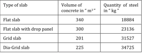
[image:5.595.36.283.450.541.2]4.4 Material requirement for various slabs
Table 12 : Quantity of materials required for each floor.
Type of slab Volume of concrete in “ m3 ”
Quantity of steel in “ kg ”
Flat slab 340 18884
Flat slab with drop panel 300 23136
Grid slab 201 31527
Dia-Grid slab 225 34725
5. CONCLUSIONS
The seismic behaviour of G+5 building considering various types of slab systems i.e, flat slab, flat slab with drop panel, grid slab and dia-grid slab including soil structure interaction is studied. The following are the major conclusions:
1. Base shear is maximum in Dia-Grid slab system and least in Grid slab system.
2. Storey displacement for Dia-Grid slab system is least and Flat slab system has higher value.
3. Columns faces lower axial forces and bending moments in Grid slab system when compared it with remaining models.
4. percentage change in base shear and storey displacement is higher in Dia-Grid slab system which has lower Time period when compared with remaining models so it is stiffer than others.
5. By observing soil structure interaction effect, we have to conclude that stiffer structures are more sensitive to soil profile effect.
6. Here, Flat slab system required higher amount of concrete and lower amount of steel, Grid slab system required lower amount of concrete and Dia-Grid slab system required higher amount of steel.
SCOPE OF FUTURE WORK
Here only low rise building are considered with isolated footings. So it is better to compare these models on raft foundations and consider tall buildings like sky-scrapers on different types of foundations. And study seismic behaviour of all these models with infill stiffness, shear walls in different seismic zones and in three types of soils.
REFERENCES
1. Mahesh bakale and T.S. Viswanathan [2017]. Seismic Behaviour of Multi-story Structure With Different Types of Slabs, International Journal of Civil Engineering and Technology (IJCIET), Volume 8, Issue 4, April 2017, pp. 507-517 Article ID: IJCIET_08_04_057, ISSN Print: 0976-6308 and ISSN online: 0976-6316.
2. Navjot Kaur Bhatia and Tushar Golait [2016]. Studying the Response of Flat Slabs & Grid Slabs Systems in Conventional RCC Buildings, International Journal of Trend in Research and Development, Volume 3(3), May-Jun 2016, ISSN: 2394-9333.
3. Gourmma G and Dr. Jagadish Kori G [2015]. Seismic performance of Different RC Slab systems For Tall Buildings, International Journal of Research (IJOER), Volume 4, Issue 4, July-Aug 2015, ISSN: 2321-7758.
4. Mohammed Fatir, M.H. Kolhar and Anjum Algur [2016]. Relative Study of Seismic Analysis Between Flat Slab And Grid Slab of RCC Structures With Different Masonry Infills In Two Different Zones, International Journal of Research in Engineering and Technology (IJRET), Volume 5, Issue 07, July 2016, eISSN: 2319-1163, pISSN: 2321-7308.
© 2018, IRJET | Impact Factor value: 6.171 | ISO 9001:2008 Certified Journal | Page 3502 6. Krishna G Nair and Akshara S P [2017]. Seismic
Analysis of Reinforced Concrete Buildings-A Review, International Research Journal of Engineering and Technology (IRJET), Volume 04, Issue 02, Feb 2017, eISSN: 0056, pISSN: 2395-0072.
7. Ghalimath A.G, More Sheetal A, Hatti Mantesh A and Jamadar Chaitrali A [2015]. Analytical Approaches for Soil Structure Interaction, International Research Journal of Engineering and Technology (IRJET), Volume 02, Issue 05, Aug 2015, eISSN: 2395-0056, pISSN: 2395-0072.
8. Mr. Magade S.B and prof. Patankar J.P. Effect of Soil Structure Interaction on The Dynamic Behaviour of Buildings, IOSR Journal of Mechanical and Civil Engineering (IOSR-JMCE), ISSN: 2278-1684, PP: 09-14.
9. Book of “ Soil-Structure Interaction For Building Structures ” by NEHRP Consultants Joint Venture. A partnership of the Applied Technology Council and the Consortium of Universities for Research in Earthquake Engineering. NIST 12-917-21.
10. Himanshu Jhinkwan and P.K. Jain [2016]. Prediction of Shear Wave Velocity Using SPT-N Value, International Journal of Current Engineering and Scientific Research (IJCESR), Volume 3, Issue 7, ISSN: 2393-8374, ONLINE: 2394-0697.
11. IS 456 : 2000 Plain and Reinforced Concrete – Code of Practice.
12. IS 13920 : 1993 Ductile Detailing of Reinforced Concrete Structures Subjected to Seismic Forces – Code of Practice.
13. IS 1893 (Part 1) : 2002 Criteria for Earthquake Resistant Design of Structures.
14. IS : 875 (Part 1) – 1987 Code of Practice for Dead Loads for Buildings and Structures.
15. IS : 875 (Part 2) – 1987 Code of Practice for Imposed Loads for Buildings and Structures.
16. “ Earthquake Resistant Design of Structures ” by S K Duggal.
17. “ Earthquake Resistant Design of Structures ” by Pankaj Agarwal.
18. “ Design of Reinforced Concrete Structures ” by N. Krishna Raju.
19. “ Soil Mechanics and Foundation Engineering ” by Dr. K.R. ARORA.
BIOGRAPHIES
Mr. Manchem Lakshmi prakasam obtained his B. Tech (Civil Engineering) from A.K.R.G Engineering College, Nalljerla. currently studying M. Tech
(structural Engineering) in S.R.K.R Engineering College, Bhimavaram.