© 2018, IRJET | Impact Factor value: 6.171 | ISO 9001:2008 Certified Journal | Page 3803
Microcontroller Based EOG and Accelerometer Guide Wheelchair
Nikesh Borkar1, Tridev Dongare2, Pratik Chahande3, Jay Bonsod4, Dr. A. B. Jirapure5
1234B.E. Scholar, ETC, Priyadarshini College of Engineering, Nagpur, India 5Assistant Professor, ETC, Priyadarshini College of Engineering, Nagpur, India
---***---Abstract -
Inspired by the advancement in sensor technology and learning behind working of wheelchair, in this paper we developed an automated system to control the motor rotation of wheel chair based on EOG and hand movement for physically challenged people who cannot walk due to physiological or physical illness, injury or any other disability. The proposed system is an Electrooculography (EOG) and Accelerometer (hand movement) controlled wheel chair. It is a special kind of wheel chair, which will move in the desired direction based on the eye movement or hand movement of disable person. EOG is a new technology which senses the eye signals for eye movements using electrodes. This sense data is then given to the control unit to move the wheel chair at desired direction. Also we used accelerometer in our proposed system for capturing the hand direction. This signals may also used for controlling the wheel chair. Signals received from both the units processed simultaneously by performing operations such as amplification, noise filtering, and then it is given to micro controller which drives the motors attached with wheel chair for desired movements.Key Words: Electrooculography, Microcontroller,
Motors, Accelerometer, wheelchair.
1. INTRODUCTION
[image:1.595.357.513.368.484.2]Electrooculography is a technique for measuring the resting potential of the retina. The resulting signal is called the electro-oculogram. And Accelerometer is a technique to measure the static acceleration of gravity in tilt-sensing applications, as well as dynamic acceleration, resulting from motion, shock, or vibration. The overall project idea is to study and implement the EOG and Accelerometer signal and transform them into the digital form to operate the motor operated wheel chair for helping physically disabled.
Fig -1: Basic block diagram of EOG & Accelerometer based wheelchair
[image:1.595.42.283.602.738.2]A wheelchair consists of accelerometer and electrode sensor as sensing element, CC2500 transceiver module for transmitting and receiving RF signal, a microcontroller unit a decision making device and motors to navigate the wheelchair in four directions just with your hand movement or eye movement. You just need to wear a small transmitting device in your hand which include an acceleration meter or wear electrode behind the eye. This will transmit an appropriate command to the wheel chair so that it can move into the desired direction they want. Traditional wheelchairs have some limitations in context to flexibility, bulkiness and limited functions. Our system allows the users to use hand movement or eye movement for movement and synchronize them with the movement of the Wheelchair so that they can use it with comfort.
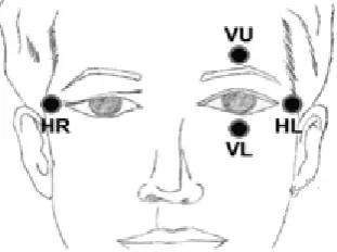
Fig -2: The electrode positions around eyes for horizontal and vertical motion
2. PROBLEM STATEMENT
The videooculography systems (VOG) or infrared oculography (IROG) based on detect the eye position using a camera. Many systems have been produced in communication from machines to human hands using keyboard, mouse, joy sticks, and touching screen etc.
But all these need normal human hands to operate. For physically challenged peoples with paralyzed muscles and not having normal functions of hand, these techniques will not help.
3. LITERATURE REVIEW
© 2018, IRJET | Impact Factor value: 6.171 | ISO 9001:2008 Certified Journal | Page 3804 mainly contained in low frequencies, band pass filter with a
range between 0.1 and 30Hz and sample rate of 128 was used. Noise was further removed by an averaging filter. Developed algorithm for EOG classification depends on derivative and amplitude level of EOG signal. Derivative of EOG signal was used to detect the edges of the signal. This algorithm found out initial edge, final edge, and area between edges. For an up movement and blink, initial edge is positive and final edge is negative. A timer calculated width of area between edges. A pulse was classified as a blink if the width of this area was smaller than 250ms.
Patterson Casmir D’Mello, Sandra D’Souza (2012) developed a Lab VIEW based EOG classification system. Ag/AgCl electrodes were used for EOG signal acquisition. To overcome the poor conductivity of skin, they used an electrolytic gel based up on Sodium Chloride. EOG signals were then amplified and filtered by using a high pass filter of 0.5Hz and low pass filter of 30Hz. M Series USB-6221 was used as a data acquisition interface. They used amplitude based EOG classification algorithm. They used the fact that amplitude of blink signal is higher than other eye movement. They compared the peak amplitude with a threshold value and if the amplitude was greater than threshold, then it was considered as a blink.
P. P. Chitee, S. B. Khemnar, A. A. Kanawade, S. B. Wakale (2016) developed a “A hand gesture based wheelchair for physically handicapped person with emergency alert system”. The system comprises of two major units. The first unit is a simple user's of two hand gesture unit. The second unit is the wheelchair unit. The first gesture unit consists of ARM7 controller which monitors the motions of fingers and transmits the corresponding control signal to the wheelchair unit. The wheelchair unit also consists of ARM7 controller for controlling the movement of wheelchair. The second gesture unit consist of ARM7 controller the controller can detect the audio announcement.
4. MATERIALS AND METHODS
4.1 Electrode
[image:2.595.330.540.79.192.2]An silver-silver chloride (Ag/AgCl Electrodes) used for carrying EOG signal. EOG signal means potential between retina and cornea of an eye area for these electrodes are located near the eye area. .silver- silver chloride electrode provides accurate and clear transmission of surface bio-potentials. We provide both DC and AC coupled Bio Amplifier for the acquisition of rapid eye movement along vertical and horizontal axes. this EOG signal are passed to the amplifier circuit by using probes as shown in above fig. this electrodes are less expensive and comfortable to user.
Fig -3: Electrodes and probes
4.2 EOG Signal Acquisition & amplification
The EOG signal have potential ranges from 0.4mV to 1mV and a pair of electrodes are commonly used to detect this signal, but the voltage difference when there’s an eye movement can be as small as just some micro volts. Due to the fact that an oscilloscope or a CPU cannot detect such small voltages, an EOG system must amplify those voltages in order to get a readable signal. Electrooculographic potential (EOG) presents a good face access, good accuracy and resolution, great range of eye displacements, works in real time and is cheap. In left gaze of the eye, the cornea approaches the electrode near the left eye, resulting in a positive going change and for right gaze, negative going change in the potential difference recorded from it.
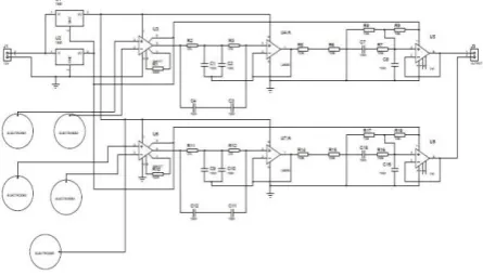
Fig -4: Amplifier and filter circuit for EOG signal An instrumentation amplifier is a type of differential amplifier that has been outfitted with input buffer, which eliminate the need for input impedance matching and thus make the amplifier particularly suitable for use in measurement and test equipment. A high pass filter is an electronic filter that passes high-frequency signals but attenuates signals with frequencies lower than the cutoff frequency. A low pass filter is a filter that passes low frequency signals with frequencies higher than the cutoff frequency. The actual amount of attenuation varies depending on specific filter design.
4.3 Accelerometer
[image:2.595.320.543.426.553.2]© 2018, IRJET | Impact Factor value: 6.171 | ISO 9001:2008 Certified Journal | Page 3805 product measures acceleration with a minimum full-scale
range of ±5 g. It can measure the static acceleration of gravity in tilt-sensing applications, as well as dynamic acceleration, resulting from motion, shock, or vibration.
The user selects the bandwidth of the accelerometer using the CX, CY, and CZ capacitors at the XOUT, YOUT, and ZOUT pins. Bandwidths can be selected to suit the application with a range of 0.5 Hz to 1600 Hz for X and Y axes and a range of 0.5 Hz to 550 Hz for the Z axis.
[image:3.595.325.539.239.420.2]
The ADXL325 is available in a small, low profile, 4 mm × 4 mm × 1.45 mm, 16-lead, plastic lead frame chip scale package (LFCSP_LQ).
Fig -5: Block diagram of accelerometer 4.4 Transceiver Module (CC2500)
The CC2500 is a low-cost 2.4 GHz transceiver Designed for very low-power wireless applications. The circuit is intended for the 2400-2483.5 MHz ISM (Industrial, Scientific and Medical) and SRD (Short Range Device) frequency band. The RF transceiver is integrated with a highly configurable baseband modem. The modem supports various modulation formats and has a configurable data rate up to 500 kBaud. CC2500 provides extensive hardware support for packet handling, data buffering, burst transmissions, clear channel assessment, link quality indication, and wake-on-radio. The main operating parameters and the 64-byte transmit/receive FIFOs of CC2500 can be controlled via an SPI interface. In a typical system, the CC2500 will be used together with a microcontroller and a few additional passive components.
Fig -6: CC2500
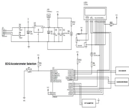
4.5 Microcontroller (Transmitter section)
[image:3.595.37.293.253.399.2]The ATmega8 provides the following features: 8 Kbytes of In-System Programmable Flash with Read-While-Write capabilities, 512 bytes of EEPROM, 1 Kbyte of SRAM, 23 general purpose I/O lines, 32 general purpose working registers, three flexible Timer/Counters with compare modes, internal and external interrupts, a serial programmable USART, a byte oriented Two wire Serial Interface, a 6-channel ADC (eight channels in TQFP and QFN/MLF packages) with 10-bit accuracy, a programmable Watchdog Timer with Internal Oscillator, an SPI serial port, and five software selectable power saving modes.
Fig -7: Transmitter section
The ATMEGA8 is used in this project due to requirement of ADC, the signal that we have taken from sensors that are in analog form that’s why we need to convert it in digital form. For that ADC is required.
4.6 Microcontroller (Receiver section)
© 2018, IRJET | Impact Factor value: 6.171 | ISO 9001:2008 Certified Journal | Page 3806 Fig -8: Receiver section
5. RESULT
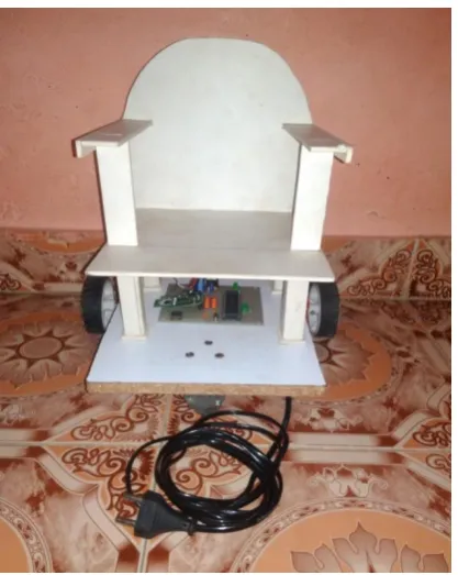
[image:4.595.318.547.347.618.2]The wheel chair thus developed will move in the focused direction based on the eye movement. The wheel chair is attached with two motors for the movement of wheel chair for different conditions. When the eye is focused up, one motor rotates the left wheel backward and another motor rotates the right wheel forward, so that the wheel chair moves towards left and vice versa for right movement. When the eye is focused right, both motors running forward and move the both wheels forward so that the wheel chair moves forward similarly when the eye is focused left the wheel chair will be stop. The conditions can be altered in the IC program according to the user’s choice. A LCD is used to display the conditions of left, right, up, down and stop.
Fig -9: Developed hardware for receiver section
Fig -10: Developed hardware for transmitter section 6. FLOWCHART
Chart -1: Main flow chart 7. FUTURE SCOPE
This small prototype of eye movement and hand movement operated wheelchair only four control signals were generated and transmitted. This can be extended to eight with a little modification in the algorithm.
[image:4.595.59.268.474.736.2]© 2018, IRJET | Impact Factor value: 6.171 | ISO 9001:2008 Certified Journal | Page 3807 Accuracy of the circuit can be improved by using
electronic components with high precision and less tolerance.
Previous work could also be useful for the effective and reliable module implementation.
8. CONCLUSION
In this paper we propose the microcontroller based wheel chair using EOG & accelerometer signals is successfully implemented and demonstrated. The final application of this wheel chair is it can be used in medical application for paralyzed and handicapped people. Also by using this signal we can control any real time machine like computer system, robot, vehicle, wheelchair etc.
ACKNOWLEDGMENT
Thanks to Dr. A. B. Jirapure for his continuous support. It was not possible to complete this work without his proper guidance.
Thanks to our family that support us in various field such as fund, idea and moral in completing the project.
The authors are very much thankful for the support provided by the Department of Electronics Telecommunication Engineering, RTMNU University, Nagpur.
REFERENCES
[1] International Journal on Recent and Innovation Trends
in Computing and Communication ISSN: 2321-8169 Volume: 2 Issue: 6 1432 – 1436 “Novel approach of man-machine interaction using brain waves electric signals”.
[2] Úbeda A, Iáñez E, Azorín J (2011) “Wireless and portable
eog-based interface for assisting disabled people” Mechatronics, IEEE/ASME Transactions on 16: 870–873.
[3] IEEE transactions on neural systems and rehabilitation
engineering, vol. 10, no. 4, December 2002 209 “System for assisted mobility using eye movements based on electrooculography” Rafael Barea, Luciano Boquete, Manuel Mazo, Member, IEEE, and Elena López.
[4] Michita Imai, Tetsuo Ono, and Hiroshi Ishiguro “Physical
relation and expressio: joint attention for human-robot interaction”, August 2011.
[5] Barea R, Boquete L, Mazo M, López E (2002)
“Wheelchair guidance strategies using eog” Journal of Intelligent and Robotic Systems 34: 279–299.
[6] E.J Rechy Ramirez, “Head movements based control of
an intelligent wheel chair in an indoor environment”, IEEE International Conference on Roboticas and
Biometrics, pp. 1464-1469, Dec. 2012,doi: 10.1109/ ROBIO. 2012. 6491175.
[7] Sandeep, Supriya “Gesture controlled wheel-chair: A
review” IARJSET, volume 2, special issue 1, May 2015, pp 23-27.
[8] Amundson JS, Amundson SG, “A joystick controlled
wheelchair”, Biomed Sci Instrum .1991; 27:131-3.
[9] O. Mirabella, M. Brischetto, G. Mastroeni “MEMS based
gesture recognition”, proc.HSI P.599 – 604, May 2010.
[10] V.Kumar,Vignesh S.N and Barathi Kannan K, “Head