International Journal of Emerging Technology and Advanced Engineering
Website: www.ijetae.com (ISSN 2250-2459,ISO 9001:2008 Certified Journal, Volume 5, Issue 7, July 2015)
222
“Self Electricity Generation Using Solar Energy and Energy
Saving by using PIC and Incremental Conductance Method”
Vignesh Sathish
1, Srinath Visweswaran
21,2Sri Venkateswara College of Engineering
Abstract-- New technological development efficiency of solar cell is increasing everyday and it is becoming cheap also for use in regular day today production of energy. Along with this government is also providing help and subsidies in set up of new solar power plant. This all things together provide a great new platform for setup and generation of new solar power plan for individual customer. This paper proposes the concept of Maximum Power Point Tracking MPPT implemented by incremental conductance method for obtaining the maximum Possible power from the solar panel. The controller used for the same is PIC16F877A, which is used for optimizing the output power. The gate pulses from the controller are given to MOSFET, which is a part of BUCK BOOST converter. This converter regulates the input voltage accordingly and reduces the current ripple. This aspect of generating energy from solar cells is very convenient and user friendly for non-technical people. This proposal will also mark the latest development in the field of Electrical& Electronics
Keywords-- PIC16F877A, BUCK BOOST, MPPT (Maximum Power Point Tracking), Solar Panel, Incremental conductance.
I. INTRODUCTION
The solar panel acts as the major source of energy. The DC voltage obtained from the Panel is stored in the battery. This voltage through an inverter circuit is converted to 230v AC output voltage, which can be used for building surrounding lights & staircases as
Well as main loads. The system was designed and implemented with the following goals to be intimately related to real world industrial power issues such as power quality. Since the efficiency of the PV module is only 13% the rest of the components should have high efficiency to maintain the system efficient enough for real world implementation. Under current acute power shortage scenario with increasing cost of natural gas, coal and other power generator turbine fuel, there is a very urgent and great need of finding alternate source of energy to generate electricity. Of all the renewable energy sources, solar energy received the greatest attention in the decade of the 1970’s and has been the rub of much emotion and pleasure. Many regarded it is as the solution for reducing the use of fossil and nuclear fuels and for a linear environment solar energy as a result has been the object of inflated. Overly optimistic predictions ranging from largely supplementing to eventually replacing all the current means of production of both electric power and thermal energy requirements.
Solar energy, in sheer six does have the potential to supply voltage energy needs Electric, thermal chemical even transportation fuels it is however, very diffuse cyclic and often undependable. Although solar energy may be used in many markets such as in active and passive space heating and cooling industrial process heating ,desalination and in electric generation. After investments by federal and agencies amounting to several hundred million dollars in the 1970’s and all these technologies, only one is in commercial use today. Namely flat plate collectors for water heating .All other remain in various stages of research and development .It now appears that solar electric systems are not expected to make engineering and economic sense as central generating plants of hundreds of mega watts capacities in the foreseeable future [1]. In order to increase the range of applicability of solar electric systems new techniques and components are introduced in the proposed systems.
Power output of solar module changes with change in direction of sun, changes in solar isolation level and with varying temperature. There exists a peak power corresponding to a particular voltage and current. Since the module efficiency is low it is desirable to operate the module at peak power point so that the maximum power can be delivered to the load under varying temperature and at isolation condition . Hence maximization of power improves the utilization of the solar PV module. A Maximum Power Point Tracker (MPPT) is used for extracting the maximum power from the solar PV module and transferring the power to the load.
The paper also describes a new PIC16F877A microcontroller based PV (photovoltaic) system. The use of this microcontroller proves many advantages as it has a reduced instruction set design. Its Codes are very efficient allowing the system to run with typically less program memory than its larger Competitors. Its clock speed is high and its costs less. It has not more than 37 instructions and operates Only with digital components and produces digital signals only[5] .Since the energy output from the sun Fluctuates with climatic conditions this controller can be very useful in adjusting the impedance of the PV system.
II.PROBLEM STATEMENT
International Journal of Emerging Technology and Advanced Engineering
Website: www.ijetae.com (ISSN 2250-2459,ISO 9001:2008 Certified Journal, Volume 5, Issue 7, July 2015)
223
The stability of the output voltage is very much improved when compared to the existing systems. (1) The Maximum Power Point Tracking MPPT
technique used in the existing System has been replaced from Constant Voltage based Peak Power Tracking method to incremental Conductance method in the proposed system. In constant voltage control method it is assumed that a maximum power point of a particular solar PV module lies at about 0.75 times the open circuit voltage of the module. So by measuring the open circuit voltage a reference voltage can be generated and feed forward voltage control scheme can be implemented to bring the solar PV module voltage to the point of maximum power. The main disadvantage with this technique is that the open circuit Voltage of the module varies with the temperature. The maximum range of temperature variance is from (0-60) 0c. The maximum irradiance level is from 200 to 1000 W/m 2. So when the temperature increases the module open circuit voltage changes and we have to measure the open circuit voltage of the Module very often. Hence the load must be disconnected from the module to measure open circuit Voltage. Due to which the power during that instant will not be utilized properly.
The disadvantages of the Constant voltage method to track the peak power under Fast varying atmospheric condition is overcome by the Incremental Conductance method. The Algorithm makes use equation
P = V * I
(P=module power = module voltage, I=module current); Differentiating with respect to dV
dP/dV = 1 +V * dI/dV
Depending on this equation the algorithm works. At the peak point,
dP/dV = 0
dI/dV = -1/V
If the operating point is to the right of the power curve then we have
dP/dV < 0
dI/dV < 0
If the operating point is to the right of the power curve then we have
dP/dV > 0
dI/dV > 0
The incremental Conductance can determine that the MPPT has reached the MPP and stop perturbing the operating point. If this condition is not met, the direction in which the MPPT Operating point must be perturbed can be calculated using the relationship between dI/dV And –I/V.
This relation ship is derived from the fact that dP/dV is negative when the MPPT is to the right of the MPP and positive when it is to the left of MPP. Hence Incremental Conductance can track rapidly increasing and decreasing irradiance conditions with higher accuracy than voltage control.
Fig 1 Power Voltage characteristivs of PV.[1]
(2) The microcontroller in the existing system is also replaced from Programmable system on chip (PSOC) microcontroller to PIC 16F877a controller in the proposed system. The architecture of PIC16F877A is much simpler than PSOC. The PIC operates only with digital components and it produces only Digital output unlike PSOC, which shows both analog as well as digital output [3]. Hence the complexity in output is greatly reduced. The optimization of the output voltage is also comparatively accurate.
(3) The proposed system also replaces the MOSFET based inverter circuit of the existing system to a circuit of BUCK-BOOST convertor connected to an inverter. The buck-boost convertor is less bulky than the MOSFET based inverter circuits. The MOSFET based system also cannot operate for light intensities above a certain level. For systems operating at high range of operating voltage a combination of MOSFET’S are required in case of MOSFET based inverter circuits. Whereas when buck boost converters are used voltage of the desired operating range can be obtained for any level of light intensity. This is possible since the buck boost convertor consists of a buck circuit as well as a boost circuit. The buck circuit reduces the voltage to operating range in case of high input voltage from the PV panel. The boost circuit on the other hand increases the input voltage to the operating range in cases when it is low [7]. Hence the usage of buck boost converter proves to be cost efficient since only a single device is used.
III. WORKING PRINCIPLE
International Journal of Emerging Technology and Advanced Engineering
Website: www.ijetae.com (ISSN 2250-2459,ISO 9001:2008 Certified Journal, Volume 5, Issue 7, July 2015)
224
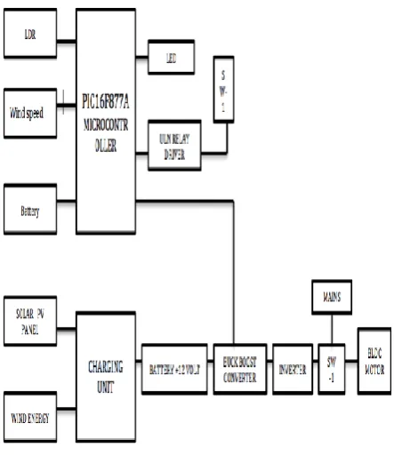
The solar cells are connected in series /parallel combination to obtain the desired power rating. By implementing the Maximum Power Point Tracking MPPT technique through Incremental conductance Method maximum possible PV voltage is obtained for light intensities at different durations of the day. On-site energy storage devices such as batteries are used for ensuring the alternate supply in case of low intensities of light. A PIC16F877A microcontroller is used for optimizing this output voltage by triggering the gate pulses to the MOSFET of the buck boost converter. This DC-DC converter (step up /step down) serves the purpose of transferring maximum power from the solar PV module to the load. This acts as an Interface between the load and the module. By changing the duty cycle the load impedance as seen by the source is varied and matched at the point of peak power with the source so as to transfer the maximum Power to the main load. There can be different types of loads used depending on the application the System being subjected such as irrigation, space heating, desalination etc. This paper proposes the Application of the system for a desalination plant. Hence a BLDC motor is used as the main load. The BLDC motor drives the mechanical pump, which is a part of the desalination plant. The pump facilitates the movement of water through a semipermeable membrane during desalination.
[image:3.595.51.273.458.714.2]
Fig 2 Basci Block Diagram
3.1 Photovoltaic technology
Photovoltaic is the field of technology and research related to the devices which directly convert sunlight into electricity. The solar cell is the elementary building block of the photovoltaic technology. Solar cells are made of semiconductor materials, such as silicon. One of the properties of semiconductors that make them most useful is that introducing impurities into their crystal lattice may easily modify their conductivity.
The intermittent nature of solar or wind power can be effectively mitigated by using a solar or wind system. Energy storage on-site (batteries) ensures that power is available when the sun isn't shining or the wind isn’t blowing. Pairing solar and wind collection systems at one site can provide diversity protection against the variable natures of both energy sources [2].
3.2 PIC16F877A Microcontroller
International Journal of Emerging Technology and Advanced Engineering
Website: www.ijetae.com (ISSN 2250-2459,ISO 9001:2008 Certified Journal, Volume 5, Issue 7, July 2015)
[image:4.595.52.279.141.422.2]
225
Fig 3 Architecture of PIC16F877A3.3.Battery
An electrical battery is one or more electrochemical cells that convert stored chemical energy into electrical energy. Here are two types of batteries: primary batteries which are designed to be used once and discarded when they are exhausted, and secondary batteries which are designed to be recharged and used multiple times.
3.4.Buck Boost DC-DC converter
The buck–boost converter is a type of DC-to-DC
converter that has an output voltage magnitude that is either greater than or less than the input voltage
magnitude. A buck (step-down) converter combined with
a boost (step-up) converter .The output voltage is typically the same polarity of the input, and can be lower or higher than the input. Such a non-inverting buck-boost converter may use a single inductor which is used for both the buck inductor and the boost inductor, sometimes called a "four-switch buck-boost converter", it may use multiple inductors but only a single switch [6].
[image:4.595.315.543.150.399.2]
Fig 4 Boost DC-DC converter
[image:4.595.106.221.682.752.2]Fig 5 Pin Diagram of PIC16F877A
3.5. LED display-
An LED display is a flat panel display, which uses an
array of light-emitting diodes as pixels for a video
display. LED displays are capable of providing
general illumination in addition to visual display, as
when used for stage lighting or other decorative
purposes. They are also energy saving compared to
LCD’s.
3.6. LDR-
The main purpose of a light dependent resistor is to change the brightness of a light in different weather conditions. This can easily be explained with the use of a watch. It is the light dependent resistor that allows the watch to know when it has gotten dark, and change the emissions level of the light at that time.
3.7. Relay driver-
International Journal of Emerging Technology and Advanced Engineering
Website: www.ijetae.com (ISSN 2250-2459,ISO 9001:2008 Certified Journal, Volume 5, Issue 7, July 2015)
226
3.8 BLDC motor – [image:5.595.320.537.151.293.2]The BLDC motor is an AC synchronous motor with permanent magnets (moving part) and windings on the Stator (fixed part). Permanent magnets create the rotor flux and the energized stator winding create Electromagnet poles. The rotor is attracted by the energized stator phases, a rotating field on the stator is Created and maintained. This action of the rotor – chasing after the electromagnet poles on the stator –is the fundamental action used in synchronous permanent magnet motors. The lead between the rotor and Rotating field must be controlled to produce torque and this synchronization implies knowledge of the rotor Position.
Fig 6 BLDC motor
IV. EXPERIMENTAL RESULT
Simulation Results
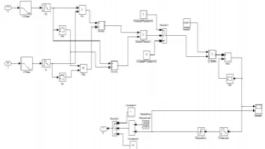
1. Matlab Simulation Model Of Mppt Unit
2. MPPT PWM Output & Output Power Of Pv Module
3. Simulation Output For Buck Boost Converter
4. Table
Table 1
Solar Panel Output Voltage of Proposed System Variable With Time Output Voltage of Solar Panel
7 AM 15.3V
9 AM 17.6 V
11 AM 18.10 V
12 PM 19.9 V
1.30 PM 17.3 V
3 PM 16.47 V
[image:5.595.100.211.300.403.2]5 PM 14.4V
Table I gives the information about solar panel output voltage with respect to time. Table shows output voltage in daytime at the afternoon solar panel voltage get exceeds as time goes increasing solar panel voltage diminishes.
V. CONCLUSION
The proposed system not only improves the efficiency by using an MPPT but also cuts down the cost considerably by using a BUCKBOOST converter instead of a MOSFET based inverter and the system is much more user friendly due to the ease of operation of a PIC when compared to a PSoC. In developing nations conservation and effectiveness of generated power plays as important a role as generating it. This system when implemented commercially can not only save a huge amount of power at the generation point but can also be used domestically as solar back up inverters.
Acknowledgement
[image:5.595.56.245.495.601.2]International Journal of Emerging Technology and Advanced Engineering
Website: www.ijetae.com (ISSN 2250-2459,ISO 9001:2008 Certified Journal, Volume 5, Issue 7, July 2015)
227
REFERENCES
[1] “Self electricity generation and energy saving by solar using
programmable system on chip (PSOC)”, The International Journal of Engineering And Science (IJES), Volume 4 Issue 2
Pages 39- 43, 2014, ISSN: 2319 – 1813.
[2] “Modeling and simulation of Incremental Conductance MPPT algorithm for photovoltaic applications”. International Journal of Scientific Engineering and Technology Volume No.2, Issue No.7, pp : 681-685 1 July 2013, ISSN : 2277-1581.
[3] Functional description of 16F877A functions and interfaces to GBT RFI monitor station. J. R. Fisher & Carla Beaudet April 26, 2005.
[4] Chapter 2, PIC16F877 microcontroller overview. Textbook Web: www.mwftr.com/book.html.
[5] An introduction to PIC microcontrollers.
[6] State-Space average modeling of DC-DC converters with parasitic in discontinuous conduction mode (DCM)., A project report by Antip Ghosh and Mayank Kandpal, IIT-Rourkela.