Smart Industrial Lighting System For Energy Saving
Purpose
Mr. Ravi Kumar K. N*, Dr. Jyothi N. S.**, Mr. Kiran Kumar N. Hittanagi***
* Electrical & Electronics Engg. Department, G Madegowda Institute of Technology, Mandya ** Electrical & Electronics Engg. Department, Malnad College of Engineering, Hassan
*** Electrical & Electronics Engg. Department, VDRK , Dharwad
DOI: 10.29322/IJSRP.9.12.2019.p9613
http://dx.doi.org/10.29322/IJSRP.9.12.2019.p9613
Abstract- The most commonly used lighting system includes fluorescent lamps, incandescent lamps, Compact Fluorescent Lamps (CFLs) and Light Emitting Diodes (LEDs). Lighting systems using has become popular because of their attractive properties like long lifetime, less power consumption, more brightness and so on making them good enough to replace the most commonly used lighting systems. Having a way to reduce the brightness with respect to the daylight illumination will help in reducing the power consumption furthermore. This is done in the proposed system in which the brightness of the lighting system using LEDs as light source gets adjusted by using PWM, buck converter and arduino where PWM technique is used to reduce the consumption of power to a noticeable level. The consumption of the power is considerable more during the peak hours than normal hours mainly because of the usage of the consumer electronics by the consumers for various purposes. So that the proposed system helps in maintaining the stability of the network.
Index Terms- Pulse Width Modulation, Light Emitting Diodes, Duty Cycle,
I. INTRODUCTION
Advancing the technology is much essential requirements in day to day life, and it plays an important role in making the world more compact, helping in more secured compact and providing more secured computing life in today’s digital world. Now a days everywhere the technology is booming. Day by day there are growing in industrial field and also there are so many achieved milestones in technical field. LED light is a semiconducting light source, when there is a current flows through it emits light.
Early, small incandescent lamps are replaced by LEDs as indicator lamps. Recently technology improved on LEDs and which can produce high output. These LEDs having advantageous such are:
They consume less energy compared to incandescent lamp.
They are having longer life.
Physically they are strong and robust.
Smaller in size and compactness.
LEDs are faster in switching.
LEDs glow brighter with less consumption of power.
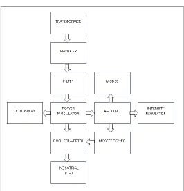
[image:1.612.313.579.365.642.2]1.Research Elaborations : 1(a)Block Diagram:
Figure 1: Block Diagram of Proposed System 1(b) Operation:
to protect the circuit from over voltage. Voltage regulator protects the Arduino from the over voltage. Arduino Uno is the central processing unit for whole circuit such as LCD, MOSFET driver, PWM and intensity regulator. The overall process is done at the Arduino Uno is displayed with the help of 16X2 LCD display. The 12V DC is applied to the supply of buck converter. The 6V DC voltage is applied to the 7805 IC. These IC is given the constant 5V at the output. Then the constant DC voltage is regulated to 8V by using the L293D IC. This voltage is applied to the power modulator. The power modulator is given the supply to all other circuits. They are Arduino, LCD display, PWM circuit and Intensity regulator.
In the proposed project there are three modes of operations are there and a manually varying the Intensity regulator is placed. This Intensity regulator provides the manual operations of varying the intensity. They are named as Mode-1, Mode-2 and Mode-3. The Mode-1 is used for day time. So in day time the sun light is there and is sufficient to work in the industry. Therefore 0% of duty cycle is applied to Mode-1. Then in morning or evening time sun light is gradually increases or decreases. So 60% of duty cycle is applied to Mode-2. In night time there is no sun light is there, so that 80% of duty cycle is applied to Mode-3. If anyone wants to more brightness then Mode-4 is has to ON. The Mode-4 is Intensity regulator. Adjust the brightness from 0% to 100%.
1(c) Controlling LED brightness using PWM:
Brightness of LED can be controlled using Pulse width modulation. Pulse width modulation indicating that here width of applied signal could be varied. When whole pulse width of signal applied, LED lamp will glow with high brightness and by decreasing pulse width of signal which will directly reduces the brightness of LED. It could be helpful whenever there is availability of light from external source that is sun light then its not needed to make LED to glow with high brightness. Hence, which consumes less power and saves electrical energy.
As now a days electrical energy playing a vital role for almost all applications. Human beings are much dependent on electrical energy. But, generation of electrical energy using different sources not so easy. Here, try has been made to save the noticeable amount of energy.
1(d) Duty-Cycle:
Duty cycle can be defined as ratio of ratio of on time to the total time period. ON time of switch can be maximum when its equal to total time period and minimum value of it is zero. Duty cycle is zero indicates switch always is in open condition over a time period.
Here, switch connects supply and load that is LED lamp. If duty cycle is 40% that means in one period, 40% of time period supply is given to load and if 80% is the duty cycle, switch connects 80% of total period from supply to load. Hence, if more time supply is connected to load, it makes the increase of LED brightness.
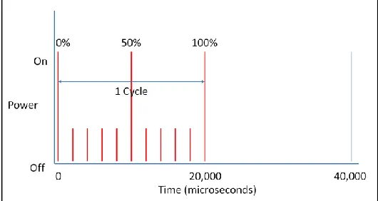
This technique is helpful for changing the brightness of LED lamp. In the day time, as the sunlight available there is no need of bright glowing of lamp. Hence duty cycle to be kept at low value. If in the evening or night, due to the darkness the duty cycle to be kept at higher value which makes the lamp to glow with high brightness. In the Figure 2, total time period of 20ms and here Ton time that is switch will be ON for 75% of 20ms that
is 15ms. Hence during which the current will flows and glows te LED but other 25% the LED is not going to glow. Figure 3 shows the duty cycle of 10%. Here the current can flows only for 10% of 20ms that is 2ms. In remaining time of period the current flows.
[image:2.612.314.575.217.359.2].
Figure 2: Power v/s Time with 75% duty cycle
1(e) PWM Resolution:
The accuracy with which it can control the duty-cycle is known as the ‘PWM resolution’. The higher our PWM resolution is, the more levels of ‘brightness’ it can display. However, since the duty-cycle is ‘fixed’ at 50Hz more resolution requires finer timing from the arduino. The faster the arduino, the smaller durations it can time. Another limiting factor is the code execution, the arduino must not only time the ‘interrupt’ which causes the pulse generation, but also run the code which controls the LED output, which must complete before the next interrupt is called. In addition, it probably want the arduino to be performing tasks other than LED PWM brightness control, so there has to be some spare execution time between interrupts to do all of the other more general processing tasks.
Figure 3: Power v/s Time with 10% duty cycle
[image:2.612.313.578.551.692.2](i) Transformer:
Transformer is a static device which is used to transfer the power from one circuit to other circuit without changing the frequency. There are two kinds of transformer. Such are
(a) Core type transformer and (b) Shell type transformer
In Core type transformer windings are surrounded over vertical portion of core which is called limb. In Shell type transformer Magnetic core surrounded over windings. In this type of transformer natural cooling is not preferable and also this type of transformer is applicable for large power applications, hence here chosen core type of transformer.
Transformers are also classified based on voltage magnitude modulations. Such are
(a) Step up transformer (b) Step down transformer
Supply voltage is given to primary winding and other side winding called as secondary winding. In step up transformer, voltage across secondary winding is greater than that of primary winding. And in case of step down transformer secondary voltage is lesser than that of primary. In the proposed work supply voltage 230V AC need to be convert to 12V and hence step down transformer is used.
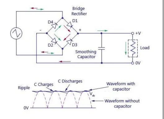
(ii)Bridge rectifier:
[image:3.612.311.541.312.497.2]A rectifier is an electrical device that converts alternating current (AC), which periodically reverses direction, to direct current (DC), current that flows in only one direction, a process known as rectification. A bridge rectifier consists of bridge arrangement to achieve full wave rectification. This is a widely used configuration, both with individual diodes wired. The bridge rectifier produces almost double the output voltage as a full wave center-tapped transformer rectifier using the same secondary voltage. The advantage of using this circuit is that no center-tapped transformer is required. The output voltage across the load resistor (+V) of the full-wave bridge rectifier described above has a large amount of ripple. A capacitor filter may be added to smoothen the ripple in the output. In this proposed project 1N4001 bridge rectifier with RC filter is used.
Figure 4 : Bridge Rectifier with RC Filter
(iii)Voltage regulator:
Voltage regulator is to provide constant voltage. This could be used for even operating AC or DC voltages. Power system involves Generating system, Transmission system and Distribution system. The main aim of Electrical service engineers is to provide co constant and continuously supply voltage to the electrical consumers.
The voltage regulators are placed at the substations and in series with the power distribution lines to provide constant voltage. For example, in single phase AC power, supply voltage will be 230volts. If the voltage crosses above the 10 percent of rated value say 250 volts then there could be affect on electrical apparatus. When voltage is below 210 volts, makes more current to flow because of which also affects on apparatus connected. Hence avoiding the fluctuation is much necessary. Here in the present work 7805 voltage regulator is used.
[image:3.612.38.302.520.712.2]7805 voltage regulator will provide +05 voltage constant supply. Capacitors are connected in the circuit as it will oppose for the rate of change of voltage. Hence maintains constant value.
Figure 5: 7805 Voltage Regulator
(iv)Liquid Crystal Display:
Its a flat panel display and for primary form of operation it uses liquid crystal. LCD crystals emit light indirectly that is using backlight. These LCD display can be used for displaying arbitrary images, preset words or digits.
Figure 6: 2X16 LCD Display
(v)Aurduino UNO:
Aurdino UNO is an ATmega 328P based microcontroller board. There are 14 digital input/output pins. Among these 6 pins can be used for PWM outputs, 6 pins can be analog inputs, Quartz crystal of frequency of 10MHz, USB connection, jack and reset button etc.
Technical Specifications of ATmega 328P microchip: It can operate at voltage of 5 volts.
Input voltage which can apply between 7 to 20 volts. There are 14 digital I/O pins.
The DC current flows per I/O pins will be 20mA. The DC current flows in 3.3V pin is 50mA. It has Flash memory of 32kB.
The speed of clock is 16MHz.
General functions of pins:
Vin: When external powersource isused, voltage can be supply to this pin through power jack.
5V: Power supplied to board either from 5V USB connector or (7 to 20)V DC power jack or from Vin pin,
output will be regulated 5V.
3V3: Voltage generated in board will 3.3V and draws maximum current of 50mA.
LED: The digital pin 13 drives built in LED. When pin value is kept to high value LED will be ON and when pin value kept to low value, then LED will be OFF.
IOREF: Voltage reference provided to operate microcontroller from this pin, either it work with 5V or 3.3V.
Reset: This pin is to add reset button which can block one in board.
GND: Ground pins.
Figure 7: Arduino Uno Board
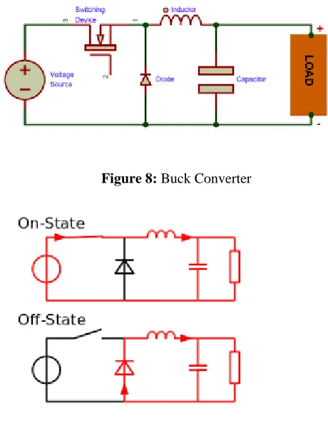
(vi)Buck converter:
Buck converter is type of DC-DC electronic converter. In Buck converter, the output voltage obtained is lesser than the magnitude of input voltage. But maintains the same power that is output and input power are same. Hence, which makes more current at the output side as power is product of voltage and current. Assuming negligible losses in the circuit.
[image:4.612.321.551.422.722.2]In the circuit when the switch is closed, current flows through inductor and stores energy in the form magnetic field and it discharges when switch is opened. The capacitor should be selected larger value such a way that value of time constant RC becomes more. Capacitor will oppose for rate of change of voltage and here voltage across capacitor is same as voltage across load.
Figure 8: Buck Converter
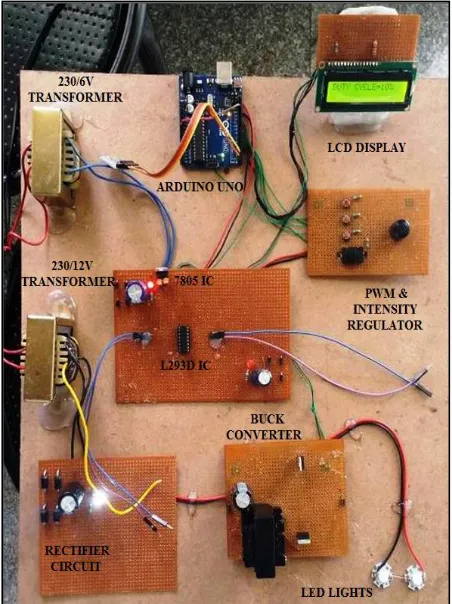
(vii)Model of the project
[image:5.612.42.268.334.636.2]In the proposed project there are three modes of operations are there and a manually varying the Intensity regulator is placed. This Intensity regulator provides the manual operations of varying the intensity. They are named as Mode-1, Mode-2 and Mode-3. The Mode-1 is used for day time. So in day time the sun light is there and is sufficient to work in the industry. Therefore 0% of duty cycle is applied to Mode-1. Then in morning or evening time sun light is gradually increases or decreases. So 60% of duty cycle is applied to Mode-2. In night time there is no sun light is there, so that 80% of duty cycle is applied to Mode-3. If anyone wants to more brightness then Mode-4 is has to ON. The Mode-4 is Intensity regulator. Adjust the brightness from 0% to 100%. After the switch ON the supply the LCD display shows the name of the project, then select anyone mode to the required intensity in the given three mode and also Mode-4 represents the manual intensity regulator. If Mode-1 is selected then PWM gives the 0% duty cycle is applied to MOSFET gate terminal. Due to this the MOSFET is the switch of the buck converter. So that ON and OFF time is varied. This implies that the charging and discharging is occurred on the inductance of the buck converter. The LED is connected to buck converter as the load. So that by varying the duty cycle intensity of the LED light is controlled and by using this method power is saved.
Figure 10: Model of the Project
(viii)Conclusion:
Smart Industrial Lighting System is successfully designed and implemented, taking into account visual comfort and energy saving of interior lighting. Controlling LED brightness using PWM and buck converter has been used for an energy saving LED control and trend consumption monitoring. Furthermore a supervision system has been deployed for the monitoring and controls the whole lighting infrastructure. The typical working day scenario has been simulated with the aim to estimate energy saving compared to a solution without sensors.
It can be conclude that proposed project using this technology can implement on real time application towards to make in India. The proposed project in terms of economical cost so it’s easily to adopt in real time application. And finally it can be conclude proposed project is most economical and easy to implement and also interface is also very easy so it can be easily adopt this technique for every industry.
(ix) Future work:
Future works are going to be focused on the development of a wireless architecture and in the evaluation of the actual energy saving taking into account the consumption of the chip radio. A valid alternative could be the implementation of the communication between the arduino board and the supervision system.
II. GETPEERREVIEWED
For peer review send you research paper in IJSRP format to
ACKNOWLEDGMENT
I KINDLY THANKFUL TO MY CO AUTHORS AND FAMILY MEMBERS ESPECIALLY MY WIFE.
REFERENCES
[1] J. Lu, X. Wu, “A Novel Multiple Modes PWM Controller for LEDs” Proc. IEEE Int’l Symp. on Circ. and Syst., pp.1767-1770, 2009.119
[2] Alonso, J.M.; Vigna, J.; Gacio, D.; Campa, L.; Martinez, G.; Osorio, R, “Analysis and Design of the Quadratic Buck-Boost Converter as a High Power-Factor Driver for Power-LED Lamps,” IECON 2010 - 36th Annual Conference on IEEE Industrial
Electronics Society, vol., no., pp.2541-2546, 7-10 Nov. 2010 doi: 10.1109/IECON.2010.5675145119
[3] A. Zhao, Wai Tung Ng, “An Energy Conservation based High-Efficiency Dimmable Multi-Channel LED Driver”, Proc. IEEE Energy Conversion Congress and Exposition, pp.2576–2580, 2011.
[4] P. Narra, D. S. Zinger, “An effective LED dimming approach”, Industry Applications Conference, 2004. 39th IAS Annual Meeting. Conference Record of the 2004. IEEE. Oct. 2004. v. 3. p.1671-1676. 119
[5] J. Garcia, A. J. Calleja, E.L. Corominas, D.G. Vaquero, and L. Campa, “Interleaved Buck Converter for Fast PWM Dimming of High-Brightness LEDs,” IEEE Trans. On Power Electronics, vol. 26, no. 9, pp. 2627-2636, 2011. 119
[6] Sameer Ram Pujari “Application of Buck Converter for LED based Commercial Lighting Systems” PESC, MIT, M.Tech Thesis -2011.
[7] Tran, Duong, and Yen Kheng Tan. "Sensorless Illumination Control Of A Networked LED-Lighting System Using Feedforward Neural Network." Industrial Electronics, IEEE Transactions on 61.4 (2014): 2113
-2121.
AUTHORS
First Author – Mr. Ravi Kumar K. N, M.Tech, B.E., G. Madegowda Institute of Technology, Bharathinagara, Mandya, [email protected].
Second Author – Dr. Jyothi N. S, phD, M.E,B.E, Malnad College of Engineering, Hassan.