674
AN ANALYSIS FOR A CLUSTER TREE ZIGBEE TOPOLOGY
1DR.MAYYADA HAMMOSHI, 2DR.AWNY SAYED
1Asstt Prof., Department of Information Technology, Ibri Colleges of Applied Sciences, Oman
2Assoc. Prof., Department of Computer Science, Faculty of sciences, Minia University, Egypt
E-mail: [email protected] , [email protected]
ABSTRACT
ZigBee or IEEE 802.15.4 is considered as a unique communication standard developed for wireless personal area network. Zigbee is a low-rate (LR) communication network which provides flexibility, very low power consumption, ease of installation, reliable data transfer, short range operation, acceptable battery life, low data rate in an ad hoc self-organizing network among inexpensive fixed, and portable moving devices. It is developed for applications with relaxed throughput requirements which cannot handle the power consumption of heavy protocol stacks.
Zigbee can be embedded in a wide range of products and applications across consumer, commercial, industrial and government markets.
Zigbee can be considered as a promising technology which has a strong impact of the development of Wireless Sensor Network since this technology is taking care of the power energy and the communication overhead.
In this paper, a cluster tree topology for 3 PAN coordinators supported by OPNET 17.5 is implemented. The aim of the study is to tests mobility, nodes leaving a network, and nodes joining a new network by measuring number of performance factors. The measured factors are: throughput, delay, load, data traffic received, end to end delay, number of hops and data traffic sent. The results showed that the PAN 2 behaved as the best tree among the cluster tree topology when compared with the other PAN s networks. The other studied issue is the mobile nodes behavior and moving among the PANs.
Keywords: ZigBee, WPAN, Tree, Mesh, Star, cluster tree, WSN
1. INTRODUCTION
ZigBee or IEEE 802.15.4 is a worldwide open standard set of communication protocols for wireless radio networks in the monitoring and control fields developed by the ZigBee Alliance (an association of international companies). ZigBee is basically developed to meet important needs such as low cost, ultra-low power consumption [11], use of unlicensed radio bands, cheap and easy installation, flexible and extendable networks, integrated intelligence for network set-up and message routing. ZigBee operates in 868 MHz, 915 MHz, and 2.4 GHz frequency bands with 250 K bits per second maximum data rate [1].
ZigBee can also be called shortly Low-Rate, which are designed to supply radio and MAC protocols allowing the designer to focus on the applications and customers’ needs. ZigBee is the architecture developed on top of the IEEE 802.15.4 reference stack model and takes full advantage of its powerful physical radio layer. It is considered as a
complete solution for the market, especially for sensor networking-based applications because ZigBee devices typically operate in limited personal operating space [6] [7].
The scope of the paper runs as follows: Section 2 gives a brief overview of the IEEE 802.15.4. Section 3 discusses network topologies. Section 4 analyzes the simulations performed. Section 5 discusses the results and gives information about tree , star and mesh topology and discuss OPNET
2. ZIGBEE /IEEE 802.15.4 (LR-WPAN) STRUCTURE
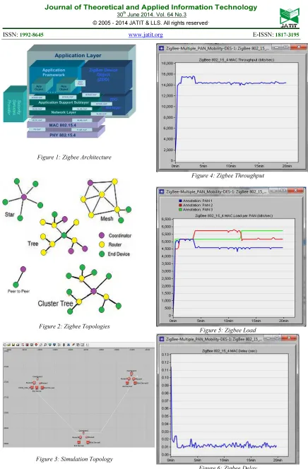
Figure (1) shows the architecture of Zigbee network. ZigBee has been developed for applications with relaxed throughput requirements which cannot handle the power consumption of heavy protocol stacks [1][2].
675 portions of the physical layer and medium access layer. In particular it defines two physicals representing three license-free frequency bands that include sixteen channels at 2.4 GHz, ten channels at 902 to 928 MHz, and one channel at 868 to 870 Mhz. The maximum data rates for each band are 250 kbps, 40 kbps and 20 kbps, respectively. The 2.4 GHz band operates worldwide while the sub-1 GHz band operates in North America, Europe, and Australia/New Zealand. The IEEE standard is intended to conform to established regulations in Europe, Japan, Canada and the United States [1] [2][3].
There are three types of devices defined by the ZigBee standards [8]. They are coordinators, routers and end-devices. The coordinator device is responsible for setting up all the network parameters such as topology, packet size, frequency band, transmission range etc. It could be considered as a superior computing capabilities node when compared to routers and end-devices. It can act as a gateway for the outside world in order to interact with the network. This role is generally assigned to the sink node. ZigBee routers are the intermediate devices in a network which route the data using optimum path from the source to the destination as well as sensing the data from their surrounding environment. ZigBee end-devices are devices with lowest computing capabilities. They are only capable of sensing data and completely depend on routers or coordinators to route their packets [9]. In another work point of view, the mentioned devices can work as either full-function devices (FFD) or reduced-function devices (RFD). A network shall include at least one FFD, operating as the PAN coordinator. The FFD can operate in three modes: a personal area network (PAN) coordinator, a coordinator or a device [11].
An RFD is intended for applications that are extremely simple and do not need to send large amounts of data. An FFD can talk to RFDs or FFDs while an RFD can only talk to an FFD. A RFD is intended for applications that are extremely simple, such as a light switches or passive infrared sensors; they do not have the need to send large amounts of data and may only associate with a single FFD at a time. Because of that, the RFD can be implemented using minimal resources and memory capacity. Two or more devices within a personal operating space (POS) communicating on the same physical channel constitute a WPAN.A network shall include at least one FFD, operating as the PAN coordinator. An IEEE 802.15.4 network is part of the WPAN family of standards although the coverage of an LR-WPAN may extend beyond the
POS, which typically defines the WPAN. Propagation characteristics for wireless media are dynamic and uncertain, thus a well defined coverage area does not exist. Small changes in position or direction may result in drastic differences in the signal strength or quality of the communication link. These effects occur whether a device is stationary or mobile as moving objects may impact station-to-station propagation [3].
3. NETWORK TOPOLOGIES
The IEEE 802.15.4 standard supports multiple network topologies like star, tree, mesh and cluster. Fitting the coordinators, routers and end-devices in these topologies varies depending on the application design choice; some applications may require the low-latency connection of the star network, e.g. PC peripherals, toys and games, and personal health care. Others may require the large-area coverage of peer-to-peer networking, e.g. perimeter security [1] [4] [5]. The legend to all topology figures are shown in figure (1). Each type of device is given a color code for easy viewing [10].
3.1 Peer-To-Peer Topology
Figure (2) shows the to-peer topology. In peer-to-peer topology, there is also one PAN coordinator. In contrast to star topology, any device can communicate with any other device as long as they are in range of one another. A peer-to-peer network can be ad hoc, organizing and self-healing. Applications such as industrial control and monitoring, wireless sensor networks, asset and inventory tracking would benefit from such a topology. It also allows multiple hops to route messages from any device to any other device in the network. It can provide reliability by multipath routing [12].
3.2 Star Topology
676 than 60000 nodes. Figure (2) shows star topology [10].
3.3 Tree Topology
In a tree network, a coordinator initializes the network, and is the top (root) of the tree. The coordinator can now have either routers or end devices connected to it. For every router connected, more child nodes can connect to the router. Child nodes cannot connect to an end device because it does not have the ability to relay messages. This topology allows for different levels of nodes, with the coordinator being at the highest level. For messages to be passed to other nodes in the same network, the source node must pass the message to its parent, which is the node higher up by one level of the source node, and the message is continually relayed higher up in the tree until it can be passed back down to the destination node.
Because the number of potential paths a message can take is only one, this type of topology is not the most reliable topology. If a router fails, then all of that router’s children are cut off from communicating with the rest of the network. Figure (2) shows tree topology [10].
3.4 Mesh Topology
A mesh topology is the most flexible topology of the three. Flexibility is present because a message can take multiple paths from source to destination. If a particular router fails, then ZigBee’s self-healing mechanism (aka route discovery) will allow the network to search for an alternate path for the message to take. In our project, one of the scenarios is to investigate this feature by removing a router from the network during operation, and seeing the end devices find an alternate path to communicate with the coordinator. The way that a message is routed from one network node to another depends on the network topology. This page provides a brief description of the possible topologies of a ZigBee network. Figure (2) shows mesh topology [10].
3.5 Cluster Tree Topology
Figure (2) shows the cluster tree topology. Cluster-tree network is a special case of a peer-to-peer network in which most devices are routers and The end devices may connect to a cluster-tree network as a leave node at the end of a branch. Any of the routers can act as a coordinator and provide synchronization services to other devices and coordinators.
Only one of these coordinators however is the PAN coordinator.
The PAN coordinator forms the first cluster by establishing itself as the cluster head (CLH) with a cluster identifier (CID) of zero, choosing an unused PAN identifier, and broadcasting beacon frames to neighboring devices. A candidate device receiving a beacon frame may request to join the network at the CLH. If the PAN coordinator permits the device to join, it will add this new device as a child device in its neighbor list. The newly joined device will add the CLH as its parent in its neighbor list and begin transmitting periodic beacons such that other candidate devices may then join the network at that device. Once application or network requirements are met, the PAN coordinator may instruct a device to become the CLH of a new cluster adjacent to the first one. The advantage of this clustered structure is the increased coverage area at the cost of increased message latency [12].
4. OPNET SIMULATION
The Optimized Network Engineering Tool (OPNET v17.5) software was used for the simulations implemented in this paper. This version of simulation model supports point to point, star, ring, tree, mesh and cluster topologies. In this paper we designed and studied the behavior of cluster tree scenario for 3 PAN networks. We calculated the performance among the three PAN networks in terms of: throughput, load, delay, data dropped, traffic sent and received, end to end delay and finally the number of hops. Below is the elaboration of the top results gained after running the scenario for 1200 seconds and updating the intervals after every 5000000 events. Figure (3) shows the simulation snapshot.
5. RESULTS
5.1 Throughput
677
5.2 Load
Figure (5) shows load for the scenario. The diagram illustrates the value for load against the simulation time values. The average load for the 3 PAN coordinators was 1,673.3, 2,251.3 and 2,813 bit/second respectively. While the routers results were 1,125.2, 562.8, 1,101.4, and 562.6 bit/second. However the end devices results were 562.6 for all of them. We found that the highest value of gained load was with the PAN2 as cumulating the load for routers 5 and 6. Also this is commensurate with the highest throughput gained for tree topology in figure (4). The load is distributed for all the devices which belong to PAN 2 structure.
5.3 Delay
Figure (6) shows delay for the scenario. The diagram illustrates the value for delay against the simulation time values. The results were 0.032186, 0.006688, and 0.006808 seconds for the PAN coordinators respectively. We can observe that lowest value was for PAN 1. The result is normal and commensurate with the low throughput shown in figure (4).
5.4 End To End Delay
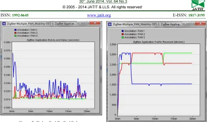
Figure (7) shows end to end delay, the results for the PAN coordinators were 0.006213, 0.006163 and 0.006138 seconds respectively, while the routers delay 0.006138, 0.042597, 0.013345, 0.013084, 0.013018 and 0.013158, however for the end devices the results were 0.090765, 0.013062, 0.032693, 0.013060 and 0.013359. As we can see that we can realize that PAN1 is having the higher delay since its having lower throughput.
5.5 Data Traffic Sent And Received
Figures (8) and (9) show data traffic sent / received for the scenario. The Two diagrams illustrate the values of data traffic received and send against time of simulation. The results were 503.47 bit/ second for traffic sent to all the PAN coordinators while, 587.9, 691.2 and less the 100 for traffic received to the 3 PAN coordinators respectively. We can see obviously that the traffic sent is the same in all the coordinators while the traffic received is higher in PAN 2 coordinator. The reason is that the throughput is higher in PAN 2 coordinator.
5.6 Number Of Hops
Figure (10) shows the number of hops. We can find that the number of hops for the coordinators is 1 while for all the routers is 2, the reason behind that is that we need to jump 2 routers in each PAN
network to transmit any messages while only one hop is needed to convey any message if we are sending via the PAN coordinator.
5.7 Pan Affiliations For Mobile Nodes
We took mobile node 1 as an example of mobile nodes. The results shows mobile_node_1 joined to PAN 1 for the first 4 minutes of the simulation. The node then briefly unjoins from the PAN1, then promptly joins PAN 2. At 12 minutes, the node unjoins from PAN 2 and promptly joins PAN 3.
6. CONCLUSIONS
Zigbee is considered as a very useful and relatively simple to use if one is using native supported model. In this paper we presented three WPAN ZigBee scenarios. They are star, mesh and tree topology respectively. The simulation studied the behavior of the topologies against throughput, delay, End to end delay, load, data traffic sent, data traffic received and number of hops. We found that PAN 2 coordinator behaved as the best tree among the cluster tree topologies and this was because of the structure of the WPAN devices. The routers in PAN 2 acts as coordinators which lets to speed up the throughput of the network. Also the mobile nodes affiliations were studied.
7. REFRENCES:
[1] IEEE 802.15.4 Task Group Web Site, 2010. [Online]. Available:
http://www.ieee802.org/15/pub/TG4.html.
[2] Abhiram Devineni ,”performance evaluation of body area network using ZigBee protocol,Msc thesis electrical engineering dept ,university of San Diego State,2011.
[3] S. C. Ergen, “ZigBee/IEEE 802.15.4 Summary”, 2004. Available:
www.sinemergen.com/zigbee.pdf.
[4] H. Son, K. Hwang, K. Kim, W. Lee, J. Kim, and D. Eom, 2010, Synchronized-slotted CSMA-CA Algorithm for Energy Efficient Peer-to-peer Multihop Communication in IEEE 802.15.4 [Online].
Available:
http://faculty.kfupm.edu.sa/coe/mayez/Selectedp apers-March-7-2010/1121052686SSCC-submit.pdf.
678 [6] Wi-fi, Bluetooth, Zigbee and Wimax, h. labiod,
h. afifi,c. de santis, Springer, 2007.
[7] Sukhvinder S. Bamber and Ajay K. Sharma, “Comparative Performance Investigations of different scenarios for 802.15.4 WPAN”, IJCSI International Journal of Computer Science Issues, Vol. 7, Issue 2, No 4, March 2010. [8] Z. Alliance, Z, “Zigbee specification v1.0”,
June 2008.
Available at http://www.zigbee.org.
[9] Harsh Dhaka, Atishay Jain, Karun Verma, “Impact of Coordinator Mobility on the throughput in a Zigbee Mesh Networks”, IEEE 2nd International Advance Computing Conference, 2010.
[10] Sam Leung, Wil Gomez and Jung Jun Kim,“ZIGBEE Mesh Network Simulation Using OPNET and Study of Routing Selection”, MS.C project, Simon Fraser University, 2009.
[11]ATA ELANI AND ADAM GSCHWENDER ,ZIGBEE
WIRELESS SENSOR AND CONTROL NETWORK,
PRENTICE HALL ,2009.
679 Figure 1: Zigbee Architecture
[image:6.595.84.520.66.730.2]Figure 2: Zigbee Topologies
Figure 3: Simulation Topology
Figure 4: Zigbee Throughput
Figure 5: Zigbee Load
680 Figure 7: Zigbee End-To-End Delay
[image:7.595.91.509.359.570.2]Figure 8: Zigbee Traffic Sent Bit/Sec
Figure 9: Traffic Received Bit/Sec