FAULT RECOVERY ALGORITHM USING KING SPARE
ALLOCATION AND SHORTEST PATH SHIFTING FOR
RECONFIGURABLE SYSTEMS
1 PRADEEP C 2 Dr. R. RADHAKRISHNAN 3 Dr. PHILIP SAMUEL
1
Associate Professor, Department of ECE, SAINTGITS College of Engineering,Kottayam,India
2Principal, Sri Shakthi Institute of Engineering &Technology, Coimbatore,India
3Associate Professor, Division of IT, Cochin University of Science and Technology, Cochin,India
Email: [email protected] , [email protected] , [email protected]
ABSTRACT
Field Programmable Gate Arrays (FPGAs) have the capability of reconfiguring in-field and at runtime that helps in fault recovery. FPGAs are used to implement complex functions in applications such as nuclear systems, space missions, communication systems etc where system reliability is very critical. Such systems must be designed with the capability of fault tolerance. A wide range of fault tolerance techniques have been proposed for FPGAs ranging from architectural redundancies to fully online adaptive implementations. This paper presents an algorithm for efficient fault recovery using king spare allocation technique and Dijkstra’s shortest path shifting. This algorithm can be applied to any modern FPGA that has partial reconfiguration (PR) capability. PR allows to modify parts of the design of the operating FPGA without affecting the other parts. The normal system operation can be ensured in noisy environment using this algorithm. This fault recovery algorithm is demonstrated using Matlab.
Keywords:- Field Programmable Gate Arrays (Fpgas), Fault Tolerance, Transient Fault, Permanent Fault, Spare,
Shifting.
1.INTRODUCTION
Reliable performance of the hardware has been the requirement of the electronic system since the first electronic systems were constructed. Improper functioning of the logic circuits in the digital systems can result in permanent or transient deviations of the values of logic variables from the designed values [1]. Permanent faults alter the inplemented logic functions permenently due to the in the logic circuit components. Transient faults are caused either by external influences such as noise in power supply, electromagnetic interference, etc. or by temporary circuit malfunctions such as overload, overheating conditions etc. Transient faults results in temporary changes in logic circuit properties. To achieve reliability for systems operating in remote /hostile areas various self-repairing methodologies are investigated.
Fault tolerance is a very important characteristic of modern electronic system, especially where immediate human intervention is not possible. The greater the benefits the electronic systems provide, the greater will be the harm when their function gets altered or when they fail. Avizienis in 1967 formulated the
concept of fault tolerance as “We say that a system is fault-tolerant if its programs can be properly executed despite the occurrence of logic faults” [2].
Dual modular redundancy (DMR) and triple modular redundancy (TMR) were used in the early stages for the development of fault tolerant systems [3], [4]. Three equivalant hardware models are implemented and the faulty cell is identified by comparing the outputs of same module is compared in TMR method.The major drawbacks of this method are areaoverhead, limited resolution and cost of implementation.Also the fault is identified only up to the functional module level.
faulty block will be isolated.Multicellular organization, cellular division and cellular differentiation are the three features of the embryonics project. Adaptive hardware systems that perform error detection and recovery through dynamic routing, reconfiguration and on-chip reprogramming were suggested [8]. Lookup table (LUT) based self healing digital systems were designed that replaces a faulty cell with spare cell [9], [10].
The functional blocks of FPGA is partitioned in to working area and self testing area in the methods proposed in [11]-[13].Fault testing and diagnosis is performed in the working area without interrupting the normal working of the system.The entire FPGA will be tested without any additional system down time to maintain high fault tolerance.This method also enables the reuse of faulty logic block.
To achieve fast fault recovery precompiled configuration technique has been investigated in [14], [15]. Here reprogramming was not necessary as the alternative configurations was prepared in advance. But it was a tedious task to prepare all the configuration versions so as to cover the possible faulty cases.
In this paper, the proposed system make use of king spare allocation technique and Dijkstra’s shortest path shifting to carry out self repair. This algorithm provides an efficient
method for enhancing the system reliability by providing self-repairing capabilities with minimum overhead. Eight functional cells share a single spare cell. The spare cell differentiates as a functional cell when a fault is detected.
The rest of the paper is organized as follows. Section II discusses the previous worksThe previous works are discussed in Section II.The fault recovery procedure in the proposed work is discussed in Section III.A comparison of proposed work with previous work is presented in Section IV. The simulation result of proposed algorithm is geven in Section V and the paper concludes with metioning the future scope in Section VI .
2.PREVIOUS WORKS
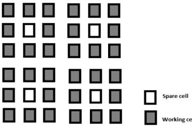
Self-propagation and self-healing characteristics of biological organisms were used in the design of digital systems by Lala [9], [10]. The rerouting in the self healing approach is demonstrated in Fig.1. In this architecture all the router cells are identified as R, functional cells as F and spare cells as S. When a functional cell is faulty, a suitable spare is selected to replace the faulty cell. Here the spare cells and the router cells has some additional decision making circuitry to decide on which spare cell to replace the faulty cell as each functional cell is surrounded by two spare cells
[image:2.612.98.508.458.604.2]
(a) (b)
Figure 1: Fault Recovery in Self Healing Approach (a) State Before The Fault Occurrence. (b) State After The Fault Occurrence. S1 is Replaced By F2.
In a method proposed by Kim, S.et al. in [16] fast fault recovery of digital sytem is presented. The architecture was inspired from the concept of paralogous genes [17]. A Working module consist of 16 working cells, 16 redundancies and 4 stem cells and each working cell has its own fault detection circuit. Here a faulty working cell is instantly replaced by its
Figure 2: Architecture of Working Module [16]
3.PROPOSED WORK
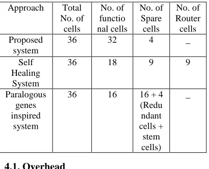
[image:3.612.106.296.516.642.2]This self-repairing algorithm makes use of king spare allocation technique. Here a spare cell is shared by eight working cells. In the chess game, the King has the capability of protecting the 8 cells surrounding the cell in which it is located [18]. The allocation technique resembles this and hence the name. Eight working cells and one spare cell together constitute a section. Fig.2 shows four such sections. If a spare is available in a section then whenever a working cell in that particular section is faulty, the spare is differentiated to replace the faulty cell regardless of whether the fault is transient or permanent. But if a spare is unavailable in a particular section, then self test is first performed and if the fault is permanent we perform the shifting to the nearest available spare else the cell undergoes delayed transient fault recovery. This algorithm can recover a number of transient faults as we opt for delayed transient fault recovery in the absence of spare. The permanent fault coverage is limited to the number of spares available.
Figure 3: King Spare Allocation.
When a fault is detected in a working cell, i.e. if “fault = 1” then the spare of that section differentiates as the new working cell if the spare is available. The faulty cell then undergoes self test. If ST OK = 1, then the fault is transient and
the spare cell undergoes dedifferentiation and the faulty cell is again configured as a working cell. If fault = 1 is detected in a working cell and if there is no spare available in that section. Then self test is performed on the faulty cell to identify the type of fault. If the fault is transient the system selects delayed transient fault recovery to reduce the routing complexity. But if the fault is permanent, Dijkstra’s shortest path algorithm is used to determine the shortest path to the available spare in other sections. Once the shortest path is determined it is checked whether all the cells in that path is fault free (i.e. determine the shortest fault free path). If the shortest path is fault free then we performing the shifting of cells along that path else we identify second shortest fault free path and so on. The pseudo code of this algorithm 1.
Algorithm 1: Pseudo code of fault recovery algorithm.
1: if Fault info = 1 then 2: Identify the faulty Cell
3: Check for the Spare Availability
4: if Corresponding section spare available then 5: Spare differentiates as working cell. 6: Faulty cell undergoes self-test to identify
the
type of fault. 7: if ST OK =1 then
8: Recovery of faulty cell and differentiation
of spare cell. 9: Go to Step 14
10: if Corresponding section spare is not available
& ST OK = 1 then
11: Delayed Recovery of faulty cell. 12: end if
13: end if 14: Go to Step 1
15: Check spare availability in any section. 16: if Spare is available then
17: Determine the shortest fault free path to spare.
18: Perform shifting if fault free path exist. 19: Go to step 6
20: Faulty cell undergoes apoptosis. 21: end if
This self-repairing algorithm involves greatly reduced overhead but at the expense on increased routing complexity. The entire system can recover upto four permanent faults and an unlimited number of transient faults.
3.1 Dijkstra’s Shortest Path Routing Algorithm.
Dijkstra's algorithm is a graph search algorithm. This algorithm solves the single-source shortest path problem. Dijkstra’s algorithm finds the shortest path between two specified vertices (nodes) [19],[20]. The starting node is called as the initial node. Dijkstra's algorithm will assign some initial distance values and will try to improve them step by step.
Step 1: Every node is assigned a tentative distance i.e. zero for the initial node and infinity for all other nodes.
Step 2: All the nodes are marked as unvisited. Set the initial node as current. An unvisited set consisting of all nodes except the initial node is created.
Step 3: Consider all unvisited neighbors for the current node and calculate their tentative distance. If this distance is less than the previously recorded tentative distance, then overwrite that distance. A neighbor is not marked visited at this time even though it is examined and it remains in the unvisited set.
Step 4: Mark the current node as visited and remove it from the unvisited set when all of the neighbors of the current node have been considered. A visited node will never be checked again.
Step 5: Stop if the smallest tentative distance among the nodes in the unvisited set is infinity or if the destination node has been marked visited. The algorithm has finished.
Step 6: Select the unvisited node that is marked with the smallest tentative distance, and set it as the new "current node" then go back to step 3.
4.COMPARISON WITH PREVIOUS
WORKS
The cell replacement and rerouting process of the proposed system is different from that of the
[image:4.612.316.521.199.365.2]previous works. The proposed algorithm is compared with the self-healing approach by P.K Lala et al. and the paralogous genes inspired algorithm by Kim, S et al. The three approaches are compared for a 6 X 6 square matrix as shown in table 1.
Table 2: Hardware Comparison Of Three Architectures In 6 X 6 Matrix Array Of Cells.
Approach Total No. of cells No. of functio nal cells No. of Spare cells No. of Router cells Proposed system
36 32 4 _
Self Healing
System
36 18 9 9
Paralogous genes inspired
system
36 16 16 + 4
(Redu ndant cells + stem cells) _ 4.1. Overhead
In our analysis spare cells are considered as overhead whereas the router cell is not considered as overhead [9]. The percentage overhead of the proposed system is calculated and a coparison with other methods are shown in figure 4 and figure 5.
4.2 Fault Coverage.
Figure 4: Area Overhead Figure 5: Permanent Fault coverage
5.EXPERIMENTAL RESULTS
The functioning of the proposed self-repairing algorithm is also demonstrated using Matlab. The four spare cells and 32 working cells are implemented as rectangles. Figure 6 shows the cell arrangement with four sections.
Figure 6: Cell arrangement
The working cells are labeled using numbers starting from 1 to 32. Section I consist of working cells 1 to 8 and the spare cell labeled as A. Section II consist of working cells 9 to 16 and the spare cell labeled as B. Section III consist of working cells 17 to 24 and the spare cell labeled as C. Section IV consist of working cells 25 to 32 and the spare cell labeled as D.
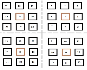
5.1 Transient Fault Recovery With Section Spare Availability.
Consider the case with cell 1 faulty. When a faulty cell is detected if the spare cell of that section is available then the spare cell differentiates as the new working cell. Here spare A is available hence it differentiates as the
working cell 1 and the faulty cell undergoes test (T). Now, if the fault is identified as transient the cell 1 recovery and spare dedifferentiation occurs as shown in Figure 7.
5.2 Transient Fault Recovery With No Section Spare Availability.
Consider the case with cell 1 faulty. Here spare A is not available as it is differentiated as cell 3 (due to a permanent fault at cell 3) hence the faulty cell undergoes test (T). Now, if the fault is identified as transient the cell 1 recovers after a delay, i.e. it undergoes delayed transient fault recovery as shown in Figure 8.
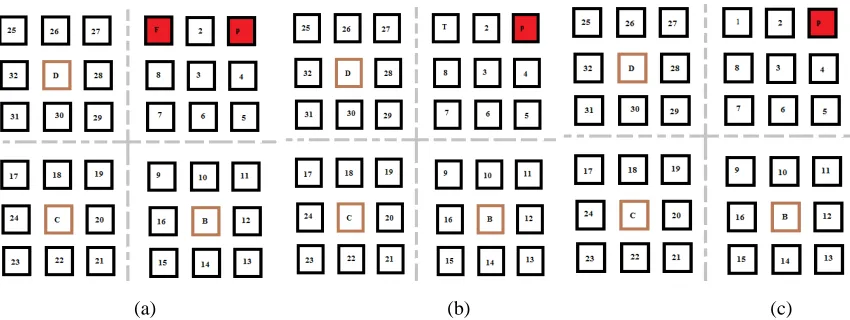
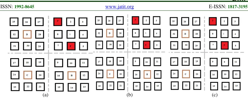
5.3 Permanent Fault Recovery With Section Spare Availability.
Consider the case with cell 1 faulty. Here spare A is available hence it differentiates as the working cell 1 and the faulty cell undergoes test (T). Now, if the fault is identified as permanent the faulty cell 1 becomes unavailable as is labeled as P as shown in Figure 9.
5.4. Permanent Fault Recovery Without Section Spare Availability.
[image:5.612.97.269.356.495.2]
(a) (b) (c)
Figure 7: Transient Fault recovery with section spare availability
(a) (b) (c)
Figure 8: Transient Fault recovery without section spare availability
[image:6.612.95.520.325.485.2](a) (b) (c)
[image:7.612.90.522.70.241.2]
(a) (b) (c)
Figure 10: Permanent Fault recovery without section spare availability
6.CONCLUSION AND FUTURE WORK
An alogorithm for self repair with leass area overhead and high fault coverage is presented in the paper. This algorithm makes use of king spare allocation technique to achieve the desired objective of reduced overhead. In the absence of suitable spare in a
faulty section this algorithm performs shifting to achieve fault recovery. This algorithm is a suitable option to design digital system with built in self repair capabilities if we cannot afford high area overhead.
As a future work the above algorithm can be implemented in selfreparable embedded system core which uses the FPGA with dynamic partal reconfiguration facility.
REFERENCES
[1]. A. Avizienis, “Design of Fault- Tolerant Computers,” Fall Joint Computer Conference, 1967, pp. 733–743.
[2]. [2] A. Avizienis,“Toward Systematic Design of Fault- Tolerant Systems,” IEEE Computer, pp. 51–58, April. 1997.
[3]. R. E. Lyons and W.Vanderkulk, “The use of triple modular redundancy to improve computer reliability,” IBM J., vol. 6, no. 2, pp. 200–209, Apr. 1962.
[4]. M. Abramovici and C. Stroud, “BIST-based test and diagnosis of FPGA logic blocks,”IEEE Trans. on VLSI Syst., vol. 9, no. 1, pp. 159-172, 2001.
[5]. Edward Stott, Pete Sedcole, Peter Y. K. Cheung, “Fault Tolerant Methods For Reliability In FPGAs”, Field Programmable Logic and Applications, 2008. FPL2008.
International Conference , pp. 415–420, Sept. 2008.
[6]. D. Mange, E. Sanchez, A. Stauffer, G. Tempesti, P. Marchal, and C. Piguet, “Embryonics: A new methodology for designing field-programmable gate arrays with self-repair and self-replicating properties,” IEEE Trans. Very Large Scale
Integr. (VLSI) Syst., vol. 6, no. 3, pp. 387–
399, Sep. 1998.
[7]. D. Mange, M. Sipper, A. Stauffer, and G. Tempesti, “Towards robust integrated circuits: The embryonics approach,” Proc. IEEE, vol. 88, no. 4, pp. 516–541, Apr. 2000.
[8]. W. Barker, D. M. Halliday, Y. Thoma, E. Sanchez, G. Tempesti, and A. M. Tyrrell, “Fault tolerance using dynamic reconfiguration on the poetic tissue,” IEEE
Trans. Evol. Comput., vol. 11, no. 5, pp.
666–684, Oct. 2007.
[9]. P. K. Lala and B. K. Kumar, “An architecture for self-healing digital systems,” J. Electron. Test.: Theory Appl., vol. 19, no. 5, pp. 523– 535, Oct. 2003.
[10].P. K. Lala, B. K. Kumar, and J. P. Parkerson,“On self-healing digital system design,” ELSEVIER Microelectron. J., vol. 37, no. 4, pp. 353–362, Apr. 2006.
[11].M. Abramovici, C. Stroud, and J. Emmert, “On-line BIST and BIST based diagnosis of FPGA logic blocks,” IEEE Trans. Very Large Scale Integr. (VLSI) Syst., vol. 12, no. 12, pp. 1284–1294, Dec. 2004.
[13].M. Abramovici, C. Stroud, S. Wijesuriya, C. Hamilton, and V. Verma, “Using Roving STARs for on-line testing and diagnosis of FPGAs in fault-tolerant applications,” in Proc. Int. Test Conf., 1999, pp. 973–982.
[14].J. D. Hadley and B. L. Hutchings, “Designing a partially reconfigured system in FPGAs for fast board development and reconfigurable computing,” in Proc. SPIE 2607, 1995, pp. 210–220.
[15].E. J. McDonald, “Runtime FPGA partial reconfiguration,” IEEE A&E Syst. Mag., vol. 23, no. 7, pp. 10–15, Jul. 2008.
[16].Kim, S. et al. "A Hierarchical Self-Repairing Architecture for Fast Fault Recovery of Digital Systems Inspired From Paralogous Gene Regulatory Circuits", IEEE Trans. Very Large Scale Integr. (VLSI) Syst. vol. PP, Issue. 99, pp. 1-14, Dec. 2011.
[17]. R. Kafri, M. Levy, and Y. Pilpel,“The regulatory utilization of genetic redundancy through responsive backup circuits,” PNAS, vol. 103, no. 31, pg. 11653–11658, Aug. 2006.
[18].R.V.Kshirsagar and S. Sharma, “Fault Tolerance In FPGA Through King Shifting”, International Journal Of Advances In Engineering & Technology, May 2012, ISSN: 2231-1963.
[19].E.W.Dijkstra, “A Note on two problems in Connexion with Graphs”, Numerische Mathematik, Vol.1, pp. 269-271,1959.