ISSN: 1992-8645 www.jatit.org E-ISSN: 1817-3195
DESIGN, ANALYSIS AND OPTIMIZATION OF A NEW
STRUCTURE OF MICROSTRIP PATCH ANTENNA FOR
RFID APPLICATIONS
ALI EL ALAMI1, SAAD DOSSE BENNANI2, MOULHIME EL BEKKALI3, ALI BENBASSOU4
1, 3, 4
University Sidi Mohamed Ben Abdellah, Higher School of Technology, Fez, Morocco Laboratory of Information Processing and Transmission
Route d'Imouzzer, BP 2427- 30000- Fès, Maroc
2University Sidi Mohamed Ben Abdellah, National School of Applied Sciences, Fez, Morocco Laboratory of Information Processing and Transmission
Quartier Industriel Ain Chkef, Route Ben Souda, BP 72, Fès Principale, 30000, Maroc E-mail: 1 [email protected]
,
2 [email protected]3
[email protected], 4 [email protected]
ABSTRACT
In this paper, we propose a new structure patch antenna excited by two identical microstrip lines having a common feeding adapted to 50 ohm and intended to applications of Radio Frequency Identification (RFID). The slots inserted at the patch antenna have a direct impact on improving the radiation characteristics in terms of reflection coefficient, voltage standing wave ratio, input impedance and directivity over a range of frequencies ranging from 2 GHz up to 2.9 GHz.
The analysis and optimization have been performed using the simulator HFSS (High Frequency Structure Simulator) based on the finite element method. Next, in order to validate our simulation, we use another electromagnetic simulator CST MWS (Computer Simulation Technology- MicroWaves Studio) which is based on the finite integration method. The simulation results of the two simulators agree well practically.
Keywords: Patch Antenna, Microstrip Line, RFID Application, Reflection Coefficient, VSWR, Input Impedance, Directivity, Simulators HFSS And CST.
1. INTRODUCTION
The concept of microstrip antennas has appeared in the 1950’s with G.A.Deshamps [1], but it will take the 1970’s to see the first achievements will be reserved primarily for military applications, and 1990’s for a real passage the industrial stage.
Two major advantages have led a very important development of this type of antenna: their low cost implementation and integration capacity. They are now implanted in many electronic devices and constitute the preferred type of antenna to microwave frequencies in modern communication systems.
A lot of researches on microstrip antennas have been published in [2, 3, 4, 5, 6, 7, 8, 9, 10].
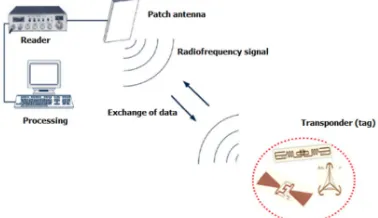
Radio Frequency Identification (RFID) is based on radio communication for tagging and identifying an object [11]. It consists of two blocks namely,
In recent years, more efforts have been made to implement RFID applications in inventory control and logistics management. RFID based system leads to significant reduction on processing time and labor as inventory in warehouses can be tracked more accurately in a simple, timely and more efficient manner. More importantly, RFID based system provides complete visibility of accurate inventory data, from manufacturer's warehouse, shop floors and brings opportunities for improvement and transformation in various process of the entire supply chain [15].
Figure 1: Functioning of an RFID system
In this paper, we propose a new structure patch antenna excited by two identical microstrip lines having a common feeding port adapted to 50 ohm and intended to applications of Radio Frequency Identification (RFID). The use of two supply lines helps minimize energy losses at the excitation port and ensure a better energy transfer injected.
The slots inserted at the patch antenna have a direct impact on improving the radiation characteristics in terms of reflection coefficient, voltage standing wave ratio, input impedance and directivity over a range of frequencies ranging from 2 GHz up to 2.9 GHz.
2. PATCH ANTENNA DESIGN 2.1. Design Principles
In general, patch antennas have been the subject many studies and developments that today find themselves in the literature. There are several analytical models useful in sizing antenna geometries such as rectangular, circular or triangular [16], [17].
The first part of the design of an antenna is the estimation its length (L) and it’s the width (W) which are calculated using equations (1-4) [18].
W (1) With f is the resonant frequency of the patch antenna, ε the dielectric constant of the substrate
and c the speed of light in free space. The effective dielectric constant ( 1) is given by:
ε
(2)
The extension of the length of microstrip patch antenna ΔL due to the fringe effect (edge effects) can be obtained by:
ΔL 0.412h .
.
– .
.
(3) So, after taking account the edge effects, the final effective length of the patch antenna can be calculated by:
L . 2ΔL (4)
2.2.AntennaConfiguration
The base antenna is composed of a rectangular microstrip patch of
the l
ength 50 and the width 56 , printed on a substrate of Rogers RT/duroid 5880, of the relative permittivity of 2.2, a thickness of 3.2 mm, the length75 and width 100 . The antenna is fed by two identical microstrip lines having a common feeding port adapted 50Ω, of the length
! 41 and the width ! 3.8 , the
assembly is placed on a ground plane of dimension
10075 as shown in figure 2.
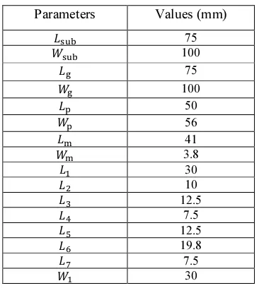
The calculation made by Matlab gave the results listed in Table 1.
Table 1: Dimensions Of Proposed Patch Antenna
Parameters Values (mm)
ୱ୳ୠ 75
ୱ୳ୠ 100
75
100
୮ 50
୮ 56
୫ 41
୫ 3.8
ଵ 30
ସ 7.5
ହ 12.5
ISSN: 1992-8645 www.jatit.org E-ISSN: 1817-3195
Top View
[image:3.595.89.519.80.400.2]
Cross View
Figure 2: Proposed Microstrip Patch Antenna
3. OPTIMIZATION OF DIMENSIONS THE PATCH ANTENNA
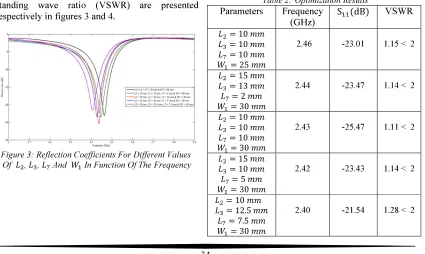
[image:3.595.96.521.514.768.2]In order to study the performance of our antenna, we will proceed to a series of simulations of the reflection coefficients on a frequency range of 2 GHz to 2.9 GHz. We keep the same dimensions shown in Table 1 and we do vary the dimensions of the slots on the radiating element inserted (, , " !"# ). The simulation results in terms of the reflection coefficients and voltage standing wave ratio (VSWR) are presented respectively in figures 3 and 4.
Figure 3: Reflection Coefficients For Different Values Of ଶ, ଷ, And ଵ In Function Of The Frequency
Figure 4: Voltage Standing Wave Ratio For Different Values Of ଶ, ଷ, And ଵ In Function Of The
Frequency
The results of optimization show that of the reflection coefficients at the input of the microstrip patch antenna exhibit a single frequency band for each variation of the dimensions of the slots. Note also that when changing the length and width of the slots, the levels of reflection coefficients successively change, which causes a decrease in the levels of the resonance frequencies found in the whole band considered.
For the dimensions of the slots (
10 , 12.5 , " 7.5 and
30 ), we see that the reflection
coefficient reaches a level of -21.54 dB to a resonance frequency of 2.4 GHz with a bandwidth of approximately 4.42. This means that the reflected power is minimal and therefore it will have a positive impact on increasing the level of the power transmitted by the microstrip antenna. Table 2 below represents the optimization results of the proposed microstrip patch antenna.
Table 2:Optimization Results
Parameters Frequency (GHz)
SdB VSWR
ଶ 10
ଷ 10
10
ଵ 25
2.46 -23.01 1.15 < 2
ଶ 15
ଷ 13
2
ଵ 30
2.44 -23.47 1.14 < 2
ଶ 10
ଷ 10
10
ଵ 30
2.43 -25.47 1.11 < 2
ଶ 15
ଷ 10
5
ଵ 30
2.42 -23.43 1.14 < 2
ଶ 10
ଷ 12.5
7.5
4. OPTIMIZATION RESULTS AND DISCUSSION
We present in this section, for comparison, the simulation results obtained using simulators CST and HFSS.
Note that the electromagnetic simulation software CST Microwave Studio is a specialized tool for three-dimensional electromagnetic simulation of high frequency components. It is dedicated primarily to microwave and RF communications such as wireless applications, but also can simulate measures electromagnetic compatibility and electromagnetic interference.
[image:4.595.94.521.79.480.2]We will proceed by following a series of simulations on the radiation characteristics of the microstrip patch antenna namely: the reflection coefficient, the input and the radiation pattern of impedance in plans E and H.
[image:4.595.102.285.392.596.2]Table 3 represents the optimized dimensions of the microstrip patch antenna.
Table 3: Optimized dimensions of the patch antenna
Parameters Values (mm)
ୱ୳ୠ 75
ୱ୳ୠ 100
75
100
୮ 50
୮ 56
୫ 41
୫ 3.8
ଵ 30
ଶ 10
ଷ 12.5
ସ 7.5
ହ 12.5
19.8
7.5
ଵ 30
4.1. Reflection Coefficient
The first simulation result is the reflection coefficient on the frequency range from 2 GHz to 2.9 GHz. This result is shown in figure 5.
Figure 5:Comparison between parameters ଵଵ found by
simulators HFSS and CST
Figure 6: Comparison between voltage standing wave ratio found by simulators HFSS and
Table 4:Comparison Of Simulation Results Obtained With HFSS And CST
Simulators Frequency (GHz)
S(dB) VSWR Bandwidth
(%)
HFSS 2.406 -21.54 1.28 < 2 4.42
CST 2.400 -26.27 1.09 < 2 11
It can be observed in figures 5-6 and Table 4, a good agreement between the results obtained by HFSS and by those CST in terms of resonance frequencies, reflection coefficient and voltage standing wave ratio. The difference between the bandwidths is not due to the mesh used in simulation and during the simulation.
4.2. Input Impedance
ISSN: 1992-8645 www.jatit.org E-ISSN: 1817-3195
Figure 7:Input Impedance Of The Patch Antenna As A Function Of Frequency
As shown figure 7, the input impedance of the microstrip patch antenna is equal to '#$
57.67 (1.24 Ω at the resonant frequency of 2.406 GHz. Indeed, the input impedance of the antenna has a resistive portion of 57.67 Ω and another reactive of -1.24 Ω at the same resonant frequency of 2.406 GHz, this means that it is suitable for almost source feeding.
4.3. Radiation Pattern
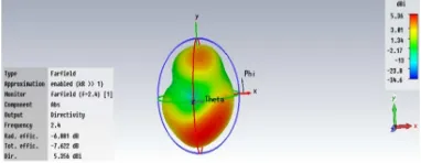
[image:5.595.92.302.106.298.2]The radiation pattern of the antenna characterizes the variation of radiated power over long distances in different directions in space. Figures 8 and 9 respectively represent the radiation pattern in 3D and 2D at frequency of 2.4 GHz.
Figure 8: Radiation Pattern Of Proposed Antenna Showing Directivity Of 5.35 Dbi
Figure 9:Directivity Of Patch Antenna Alone (Polar View)
The Directivity plot (3D View) represents amount of radiation intensity is equal to 5.35 dBi. The simulated antenna radiates more in a particular direction as compared to the isotropic antenna which radiates equally in all directions, by an amount of 5.35 dBi. From polar plot view of the directivity, it can be seen that at a frequency of 2.4 GHz, directivity is 5.24 dBi, radiation pattern obtained is omnidirectional with main lobe directed at an angle of 40 degree, having angular beam-width of 53.2 degree. The magnitude of the main lobe is 5.24 dBi.
Order to supplement the previous simulations, we propose to introduce the electromagnetic field distribution in the two E and H planes to know the levels of radiation far fields that propagate at the antenna and totaled values 1.26.10V m⁄ for E and
25.6 A m⁄ for H.
(a)
[image:5.595.98.289.496.570.2](b)
Figure 10:Field distribution, (a) E- field and (b) H-Field
5. CONCLUSION
In this paper, we presented a new structure of microstrip patch antenna and intended for RFID applications.
[image:5.595.107.278.607.703.2]The proposed antenna is a simple structure which can be easily manufactured with a low cost. It is a good solution for many wireless applications.
REFERENCES:
[1] G.A.Deshamps,"Microstrip Microwave Antennas", Third USAF.Symposium on Antennas, 1953.
[2] A. El Alami, S. D. Bennani, M. El Bekkali and A. Benbassou, "Optimization and High Gain of a Microstrip Patch Antenna Excited by Coaxial Probe for RFID Reader Applications at 2.4 GHz", European Journal of Scientific
Research, Vol. 104, No. 3, June 2013,
pp.377-391.
[3] K. R. Carver and J. W. Mink, "Microstrip Antenna Technology", IEEE Trans. Antennas
Propagat., vol. AP-29, pp. 2-24, Jan. 1981.
[4] Y. T. Lo, D. Solomon, and W. F. Richards, "Theory and Experiment on Microstrip Antennas", IEEE Trans. Antennas Propagat., vol. AP-27, pp. 137-145, Mar. 1979.
[5] B. Belentepe, "Modeling and Design of Electromagnetically Coupled Microstrip-Patch Antennas and Antenna Arrays", IEEE
Antennas Propagat. Mag., vol. 37, no. 1, pp.
31-38, Feb. 1995.
[6] O. Lafond, M. Himdi, and J. P. Daniel, "Aperture Coupled Microstrip Patch Antenna with thick Ground Plane in Millimetre Waves",
Electron. Lett., vol. 35, no. 17, pp. 1394-1395,
1999.
[7] Mahesh M. Gadag, Dundesh S. Kamshetty and Suresh L. Yogi, "Design of Different Feeding Techniques of Rectangular Microstrip Antenna for 2.4GHz RFID Applications Using IE3D",
Proc. of the Intl. Conf. on Advances in
Computer, Electronics and Electrical
Engineering,pp.522-525.
[8] Indra Surjati, Yuli KN and Arky Astasari, "Microstrip Patch Antenna Fed by Inset Microstrip Line For Radio Frequency Identifcation (RFID)", 2010 Asia-Pacific International Symposium on Electromagnetic
Compatibility, April 12 - 16, 2010, Beijing,
China, pp.1351-1353.
[9] Sanyog Rawat and Parul Pathak, "A Novel Inset Fed Patch Antenna Design for RFID at 2.4 GHz", Proceedings of International
Conference on Microwave – 08,pp.748-749.
[10]Gourav Singh Rajput, "Design and Analysis of Rectangular Microstrip Patch Antenna using
Metamaterial for better Efficiency",
International Journal of Advanced Technology
& Engineering Research (IJATER) , Volume 2,
Issue 6, Nov. 2012 ,pp.51-58.
[11]M. Jo, C. G. Lim, and E.W. Zimmers, "RFID Tags Detection on Water Content using a Back-Propagation Learning Machine", KSII Trans. On Internet and Information Systems,
vol. 1, no. 1, pp. 19–32, 2207.
[12]B. Carbunar, M. K. Ramanathan, M. Koyuturk, C. Hoffmann, and A. Grama, "Redundant-Reader Elimination in RFID Systems", in Proc.
2nd Annu. IEEE Communications and
Networks (SECON), 2005, pp. 176-184.
[13]Y. Bendavid, S. F. Wamba, and L. A. Lefebre, "Proof of Concept of and RFID-Enabled Supply Chain in a b2b E-commerce Environment", in Proc. 8th Intl. Conf. on
Electronic Commerce (ICEC06), 2006, pp.
564–568.
[14]S. E. Sarma, "Towards the Five-cent Tag", Technical Report MIT-AUTOAID WH-006, MIT Auto ID Center, 2001.
[15]Q. Wang, R. McIntosh, and M. Antony, "A RFID-Based Automated Warehouse Design",
in Proc. 2nd Intl. Conf. on Computer
Engineering and Technology (ICCET), 2010,
pp. v6-359 – v6-363.
[16]R.Garg, P.Bhartia,I. Bahl, A.Ittipiboon, "Microstrip Antenna Design Handbook", Artech House publishers, 2001.
[17]C. A. Balanis, "Antenna Theory Analysis and Design", 3rd edition, John Wiley and Sons Publication, New Jersey, 2005.