Design and Implementation of Efficient CIC Filter
Structure for Decimation
P. Durai Saravanan
PG Student / ME Computer and Communication Ganadipathy Tulsi’s Jain Engineering College
Vellore, Tamilnadu, India
V. Jayaprakasan
Professor / Department of ECE Ganadipathy Tulsi’s Jain Engineering College
Vellore, Tamilnadu, India
ABSTRACT
This paper presents a double sharpened CIC decimation filter, which consists of generalized comb filter as first stage, sharpened comb filter as second and third stage. The comb decimation filter at the first stage operates at the input sampling rate, sharpened second stage operates at lower sampling rate as compared to first stage and sharpened third stage operates at lower than the first and second stages. This reduces the sampling at every stage of the three stage CIC decimation filter. The sharpened second stage produces the narrow passband droop and better stop band alias rejection. This narrow passband droop will be compensated with the help of third stage which is sharpened section. This filter structure is designed in MATLAB Simulink environment and implemented with help of Virtex-V XC5VLX110T-3ff1136. Device utilization and simulation results are tabulated.
Keywords
MATLAB Simulink, Xilinx Virtex-V, CIC Filter, Filter sharpening.
1.
INTRODUCTION
The use of non-recursive filter structures has been increasing in the recent years for various applications. This is due to the low power consumption and increase in the circuit speed, especially when the decimation factor and the filter order are high. The frequency response of CIC (Cascaded-integrator comb) decimation filter with various techniques has been reported in the past few decades by many researchers [1-12]. In 1981, Eugene Hogenauer [12] proposed a class of digital filter for interpolation and decimation that requires no multipliers and use limited storage hereby leading to more economical hardware implementations. They are designated as cascaded integrator-comb (CIC) filter, because structure consists of an equal number of integrator section operating at the high sampling rate and a comb section operating at the low sampling rate.
A low power fifth order decimation comb filter with programmable decimation ratio (16 and 8) and sampling rate (128 MHz and 44.8 GHz) for GSM and DECT application have been proposed by Y.Gao et al [3]. The low power consumption is achieved by following approaches. First the non-recursive architecture for comb filter is employed, second unnecessary computations eliminated with polyphase implementation of each stage and third each polyphase
components implemented with data-broadcast structure. H. Aboushady et al. [4] presented a multistage polyphase
structure with maximum decimation factor in the first stage has been used. The proper choice of this first stage decimation factor can significantly improve the power consumption, area and maximum sampling frequency.
J. F. Kaiser and R.W. Hamming [8] describes the filter sharpening technique based on the idea of amplitude change function (ACF) which is restricted to symmetric non-recursive (FIR) filters with piecewise constant passband and stopband. A. Kwentus [5] designed and implemented a programmable CIC multirate decimation filter structure with filter sharpening techniques to improve the filters passband response. This allows the first stage CIC decimation filter to be followed by a fixed-coefficient second-stage filter rather than a programmable filter thereby achieving a significant hardware reduction over existing approaches. A very efficient multistage decimation filter for a sigma-delta A/D converter has been proposed by L.L. Presti [6]. In this structure, the first-stage of the filter is obtained by properly rotating the zero-pole distribution of a comb filter in z-plane and then it can be implemented by using a recursive structure.
Several schemes have been proposed by G. J. Dolecek and S.K.Mitra [7], [9-11] to design CIC filters with improved magnitude response. The authors proposed a different structure that consists of a comb section and a sharpening comb section with the latter section operating at a lower rate than the high input rate for the realization of comb-decimation filter with a sharpened magnitude response. Applying sharpening to the decimation filter in the last stage provides very good results, saving in number of operations comparing to the case of sharpening of complete filter. The main idea of this paper is to integrate the advantages of the structures presented in order to obtain the structure that can operate at a lower sampling rate while achieving better performances than the original comb filter based structure.
2.
CASCADED INTEGRATOR – COMB
FILTER
Cascaded integrator comb [1] or Hogenauer filter, are multirate filters used for realizing large sample rate changes in digital systems. CIC filters are multiplierless structures, consisting of only adders and delay elements which is a great advantage when aiming at low power consumption. So the CIC filters are frequently used in digital down converter and digital up converters. The CIC filter is a class of hardware efficient linear phase FIR digital filter consists of an equal number of stages of ideal integrator and comb filter pairs. The highly symmetric structure of this filter allows efficient implementation in hardware. However the disadvantage of a CIC filter is that is passband is not flat, which is undesirable in many applications. This problem can be overcome through the use of compensation filter. CIC filter achieve sampling rate decrease (decimation) without using multiplication. The CIC filter first performs the averaging operation then follows it with the decimation.
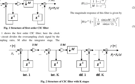
In equation (1) the numerator (1z ) represents the transfer function of comb and the denominator 1/ (1z1) indicates the transfer function of integrator.
Fig. 1 Structure of first order CIC filter
Figure 1 shows the first order CIC filter; here the clock divider circuit divides the oversampling clock signal by the oversampling ratio, M after the integrator stage. The
cascading [3] several identical comb filters which is shown in Figure 2. The transfer function of multistage comb filter composed of identical single stage comb filter is given by,
K M
z
z
M
z
H
11
1
1
)
(
(2)
The magnitude response of this filter is given by
K
j M
M e
H
) 2 / sin(
) 2 / sin( 1 ) (
[image:2.595.78.535.185.469.2](3)
Fig. 2 Structure of CIC filter with K stages
Fig.3 Response of CIC filter with different K values
Figure 3 shows the frequency response of CIC filter for different stages, while increasing the K values passband droop decreases and stopband attenuation increases.
2.1
CIC filter for sample rate Conversion
The CIC filters are utilized in multirate systems for constructing digital up converter and down converter. The ability of comb filter to perform filtering without multiplication is very attractive to be applied to high rate signals; moreover CIC filters are convenient for large conversion factor, since the low pass bandwidth is very small.In multistage decimators with large conversion factor, the comb filter is the best solution for first decimation stage, whereas in interpolation, the comb filter is convenient for the last stage.
2.2
CIC filter for decimation
The basic concept of CIC filter is given in Figure 4, which consists of factor of M down sampler and K-stage CIC filter. Applying third identity, the factor of M down sampler is moved and placed behind the integrator section and before the comb section as shown in Figure 5. Finally the CIC decimator is implemented as a cascade of K integrator, factor of M down sampler and the cascade of K differentiator sections. The integrator portion operates at the input data rate, whereas the comb portion operates at M time’s lower sampling rate.
3.
PROPOSED WORK
3.1
Proposed CIC filter design
[image:2.595.56.283.481.605.2]Fig.4 Cascade of CIC filter and down sampler
Fig.5 Cascade of integrator section, down-sampler and comb section
First Stage Second Stage (Sharpened) Third Stage (Sharpened)
Fig.6 Proposed CIC filter structure
Filter sharpening [3] is the technique to improve the passband droop and stopband attenuation using multiple realization of a low order basic filter having the form.
K p m k p n m
n H f
k n k n f H f
H [1 ( )]
! ! ! ) ( ) ( ) ( 0
1
(4)
where, Hp(f) is a low order basic filter, n and m are non-negative integers represent the number of non-zero derivatives of Hnm(f) at points Hnm(f) = 0 and Hnm(f) = 1
respectively.
The Kaiser-Hamming sharpening technique applied to linear-phase FIR filters with group delay of D samples has the transfer function of H11(z), for n=1; m=1 can be written as
)]
(
2
3
[
)
(
)
(
211
z
H
z
z
H
z
H
pD
p
(5)
The term [3z-D – 2 Hp(z)] is responsible for passband droop
reduction and Hp(z)is responsible for stopband rejection.
The magnitude response of the sharpened filter [13] is
K K i sh M M M M e H 3 2 ) 2 / sin( ) 2 / sin( 1 2 ) 2 / sin( ) 2 / sin( 1 3 ) ( (6)
The generalized transfer function of CIC filter can be written as
)
(
)
(
)
(
)
(
1 1 23 2 1 M M M
z
H
z
H
z
H
z
H
(7) Where,
11 1
1
1
1
)
(
1z
z
M
z
H
M
1 2 1 11
1
1
)
(
2 2 M M M Mz
z
M
z
H
2 1 2 11
1
1
)
(
33 M M
M M M
z
z
M
z
H
(8)The decimation factor M is subdivided in to M1, M2 and M3.
The magnitude response is
) 2 / ( sin ) 2 / ( sin 1 ) ( 1 1 1
M M eH j
) 2 / ( sin ) 2 / ( sin 1 ) ( 1 2 1 2 2 1 M M M M e
H j M
) 2 / ( sin ) 2 / ( sin 1 ) ( 2 1 3 3 2 1 M M M M eH j M M
(9)
Transfer function of proposed CIC filter structure is given by
}
)]
(
[
2
)]
(
[
3
{
}
)]
(
[
2
)]
(
[
3
{
)]
(
[
)
(
3 3 2 3 3 2 2 2 1 2 1 2 1 1 1 K M M K M M K M K M L PSz
H
z
H
z
H
z
H
z
H
z
H
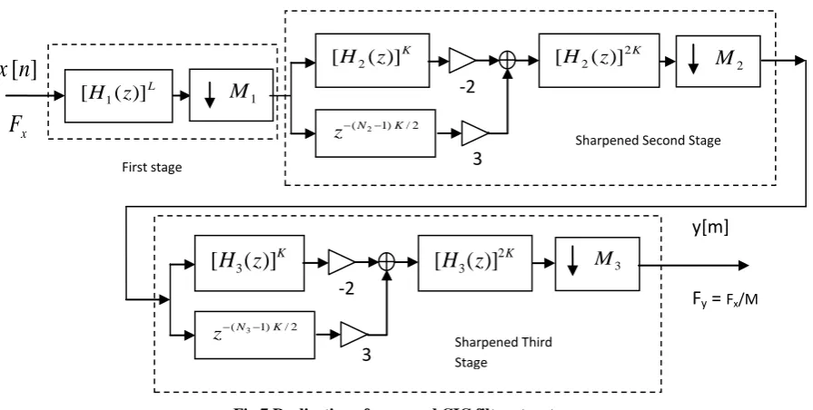
(10)Fig.7 Realization of proposed CIC filter structure
Figure 7 shows the detailed implementation scheme of proposed CIC filter structure. The first stage is comb decimator with decimation factor M1 which can be realized in either recursive or non-recursive scheme. As a result second stage (sharpened section) is moved to a lower rate which is M1 times lower than the input rate. Further the output of the second stage will be again sharpened by third stage. This will improves the passband droop performance compared to existing structure.
3.2
Implementation of Proposed CIC filter
design
The recent advancement in the VLSI technology particularly in FPGA as made possible, the realization of advanced Digital Signal Processing algorithm in high frequency domain. With this development a single chip solution is possible for complex DSP based applications like, ADC, Decimation and Interpolation in the communication system. Digital implementation couples with signal processing algorithms greatly enhance the system performance, reduced the cost and increase the reliability of the system. Low power DSP systems are implemented by changing the sampling clock for each subsystem depending on the real requirements. The sampling rate change results in aliasing; this necessitates the use of filters to overcome it. So in this paper we discuss the implementation of improved passband droop performance three stage CIC filter.
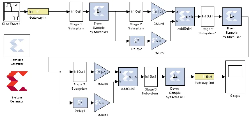
The initial model was designed and tested in Simulink, a software package from The Mathworks for modeling, simulating and implementing the dynamic systems. The Figure 9 shows the Simulink model of the proposed CIC filter structure. This Simulink model is used as the reference model for synthesis of the design in FPGA. To target the module for FPGA, we choose to use Xilinx System Generator, which provide a Simulink blockset that is then converted to Verilog
[image:4.595.344.508.368.581.2]for synthesis and implementation this flow chart is shown in Figure 8.
Fig. 8 FPGA Synthesis Flow
4.
SIMULATION AND SYNTHESIS
RESULTS
Simulation results obtained by using the proposed CIC decimation filter with sharpening technique in the second stage and third stage. In order to compare the results with the classical comb filter we found the equivalent number of the stages of the classical comb filter of the length. In the first stage we have a comb filter of length M1with L stages. In the
second and third stages we have the sharpened comb filter of length M2 and M3 with K stages.
x
F
First stage
-2
3
K
z
H
(
)]
[
32 / ) 1 (N3 K
z
Sharpened ThirdStage
K
z
H
3(
)]
2[
M
33
2 / ) 1 (N2 K
z
Sharpened Second Stagey[m]
Fig. 9 Implementation Structure of Proposed CIC Filter
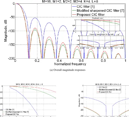
(a) Overall magnitude responses
[image:5.595.72.517.206.713.2](b) Passband zooms (c) Stop band response around the first null
(a) Overall magnitude responses
[image:6.595.76.499.77.458.2]b) Passband zooms (c) Stop band response around the first nul
Fig. 11Magnitude responses plots for M=16, M1=2, M2=2, M3=4 with K=4 and L=8
The magnitude response for the following decimation filters using matlab has been computed and given. The magnitude response of the developed proposed CIC filter structure, for M=16 with different K and L values are computed and compared with existing CIC structure. Figure 10 and 11 shows the magnitude response of (M=16, M1=2, M2=2, M3=4) proposed CIC filter is compared with existing CIC [1] modified sharpened CIC filter [7], where the passband and stopband aliasing are emphasized.
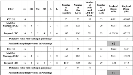
Table 1 shows the device utilization summary of basic CIC, modified CIC and Proposed CIC structure. Compared to basic CIC and modified CIC filter structure, the proposed structure utilizes additional hardware components (37% approximately) and the power consumed also high compare with the exiting,
but the proposed structure gives 62% improvement in passband droop performance.
5.
CONCLUSION
Table -1 Overall Comparison of Proposed CIC Performance with existing
Filter M M1 M2 M3 K L
Number of Slice Registers
Number of Slice LUTs
Number of fully used LUT-FF
Pairs
Number of bonded
IOBs
Passband Droop
(dB)
Stopband Droop
(dB)
CIC [1] 16 2 97 53 53 33 -0.111 -46.867
Modified Sharpened CIC
[7]
16 4 4 2 4 353 1039 327 29 -0.017 -84.225
Proposed CIC 16 2 2 4 2 4 562 1649 521 29 -0.00638 -82.225
Difference value with existing in percentage 37 37 37 - 2
Passband Droop Improvement in Percentage 62
CIC [1] 16 4 161 85 85 33 -0.223 -93.74
Modified Sharpened CIC
[7]
16 4 4 4 8 669 1409 574 31 -0.041 -177.92
Proposed CIC 16 2 2 4 4 8 1010 3085 962 29 -0.02 -174.5
Difference value with existing in percentage 34 54 40 -4
Passband Droop Improvement in Percentage 51
6.
REFERENCES
[1] E. B. Hogenauer, “An economical class of digital filters for decimation and interpolation,” IEEE Trans. Acoust. Speech, Signal Process., vol. ASSP-29, no. 2, pp. 155– 162, Apr. 1981.
[2] S. K. Mitra, Digital Signal Processing—A Computer Based Approach, 2nd ed. New York: McGraw-Hill, 2001.
[3] Y.Gao, L. Jia, and H. Tenhunen, “A fifth-order comb decimation filter for multistandard transceiver applications,” in Proc. IEEE Int. Symp. Circuits and Systems, Geneva, Switzerland, May 2000, pp. III-89–III-92.
[4] H. Aboushady, Y. Dumonteix, M. M. Loerat, and H. Mehrezz, “Efficient polyphase decomposition of comb decimation filters in Sigma-Delta analog-to-digital converters,” IEEE Trans. Circuits Syst. II, Analog Digit. Signal Process, vol. 48, no. 10, pp. 898–903, Oct.2001. [5] Kwentus, Z. Jiang, and A. Willson Jr., “Application of
filter sharpening to cascaded integrator-comb decimation filters,” IEEE Trans. Signal Process., vol. 45, no. 2, pp. 457–467, Feb. 1997.
[6] L. L. Presti, “Efficient modified-sinc filters for sigma-delta A/D converters,” IEEE Trans. Circuits Syst. II, Analog Digit. Signal Process, vol. 47, no. 11, pp. 1204– 1213, Nov. 2000.
[7] GordanaJovanovic-Dolecek and Sanjit K Mitra,”A New Two-Stage Sharpened Comb Decimator”, IEEE Trans. On Circuits and Systems, vol. 52, pp. 1414-1420, July 2005
[8] J. F. Kaiser and R. W. Hamming, “Sharpening the response of a symmetric nonrecursive filters,” IEEE Trans. Acoust. Speech, Signal Process, vol. ASSP-25, no. 3, pp. 415–422, Oct. 1977.
[9] GordanaJovanovic-Dolecek and Sanjit K Mitra, “Sharpened comb decimator with improved magnitude
response”, IEEE Trans. Acoust. Speech, Signal Process, vol. ASSP-2, pp. 929-932, 2004.
[10]GordanaJovanovicDolecek and Fred Harris,” On Design of Two-Stage CIC Compensation Filter”, IEEE International Symposium on Industrial Electronics (ISlE 2009) Seoul Olympic Parktel, Seoul, Korea, pp. 903-908, July 5-8, 2009
[11]Alfonso Fernandez-Vazquez and Gordana Jovanovic Dolecek,” Maximally Flat CIC Compensation Filter: Design and Multiplierless Implementation”, IEEE Transactions on Circuits and Systems-II; Express briefs, Vol.59, No.2, pp.113-117, February 2012
7. AUTHORS’
PROFILE
P.DuraiSaravanan received his Bachelor’s Degree in Electronics and Communication Engineering from Madras University, Chennai, India in the year 2001. He has 10 years industrial experience in an electronics based industry. Presently he is pursuing Master Degree in Computer and Communication Engineering in Anna University, Chennai, India. His areas of interest are Wireless communication and Signal Processing.