UML Modeling of Static Grid Octagonal Network
Topology for Distributed Computing
Vipin Saxena, PhD.
Department of Computer ScienceB.B. Ambedkar. University (A Central University) Rae Barely Road, Lucknow-25, U.P.
(India)
Nimesh Mishra
Department of Computer ScienceB.B. Ambedkar University (A Central University) Rae Barely Road, Lucknow-25, U.P.
(India)
ABSTRACT
In the recent year, distributed computing systems have become very popular approach of computing in comparison of old centralized computing systems due to high performance computing in a very low cost. Topological design for static interconnection of computer systems under distributed environment plays a very vital role to achieve the desired accuracy in a low cost. For the topological design, the concept of graph theory is used by the various researchers from time to time. The present work is an attempt to propose a new octagonal topological design for static interconnection of computer systems under distributed environment. All interconnected nodes are placed at equidistant and Unified Modeling Language (UML) approach is used to model the proposed network topology. UML class and sequence diagrams are designed for effective execution of incoming process inside a Process Execution Controller (PEC).
General Terms
Octagonal Grid Topology, Message Passing
Keywords
Class Diagram, Distributed Computing, Octagonal Grid Topology and Sequence Diagram
1.
INTRODUCTION
Nowdays world wide web (www) is the best structure based upon the distributed computing system in which hetrogenous collections of computer systems, handheld devices, etc. are interconnected via network links either through the fibre optics or wifi systems. The entire distributed system is based upon the connection of links, if the link fails then system attached with the link fails therefore; topological design plays a vital role for the links among the nodes. The design must be in such a way that if a link fails then network should not be failed or one can say if a link fails then communication of data must be done via another link which is functioning. From the literature, it is observed that various kinds of network topologies are proposed from time to time for static interconnection of computer systems. Different topological static structures are already proposed and implemented to form a network of interconnected nodes. The topological designs for networks have been classified into static and dynamic interconnected networks. The static and dynamic interconnections of computer systems are well explained by Hwang[1]. The static interconnections are of the categories of star, bus, ring, tree, fat-tree, mesh, torus, etc. Hwang has also explained various types of dynamic interconnection namely hypercube, omega, crossbar network, etc. Topological structure has also been represented by [2] and modeling concepts are explained by performing the process of
mutually exclusive manner in every topology. One of the main problems of the distributed computing environment is the occurrence of the deadlock. To avoid this task in a mutual exclusion manner, the concept has been applied in such a manner that it controls the execution of the processes which show that they may not create a deadlock condition throughout their condition. Critical section principles [12]-13] are used to avoid this problem. Network has been represented by graph and an algorithm has been designed to trace Hamiltonian cycles in G(n, p) graphs [14]. The proposed algorithm works in a synchronous distributed environment. From the literature, it is also observed that first time Unified Modeling Language (UML) is proposed in the year 2002 for parallel and distributed applications i.e. in the field of Advanced Computer Architecture by Pallana and Fahringer [15]-[16]. They described the activity diagram, class diagram for process executing in parallel or distributed node. On the other hand and due to evolution of object-orientation, OMG [17]-[18] group has released UML specification in year 2001 after the development of various kinds of UML diagrams by Booch et al. [19]-[20]. Recently Saxena et al. [21]-[22] have also used the UML representation for the various kinds of network topologies and computed the performance of 2D mesh, torus and hypercube, topologies which are used for static interconnection of computer systems.
The present work is the motivation from the literature and obsevered that a grid octagonal topology is not proposed by the researches. Therefore, a grid octagonal topology is proposed to connect eight computers as systems, hand-held devices, etc inside the one grid for the distributed computing systems. The links are increasing as the numbers of devices connected in the octagonal topology are increasing. The process may execute either on its node and form a shortest path to execute on the next node attached in the octagonal topology. Process Executing Controller (PEC) is fully responsible to execute the process. A UML class model is developed for execution of process through thread under octagonal grid topology. Space complexity is also measured and general formulae are developed by the authors for the search of shortest path when the grid becomes complex. Interconnected devices under distributed experiment are placed at equidistant and one link is counted as one hop counter. Results are presented in the form of tables and graphsauthors follow some simple guidelines. In essence, we ask you to make your paper look exactly like this document. The easiest way to do this is simply to download the template, and replace the content with your own material.
2.
BACKGROUND
2.1
Distributed Computing System
[image:2.595.325.538.80.231.2]Distributed computing system is defined as a collection of heterogeneous devices attached by means of topology. The system does not share the global clock but have its own processor and memory. The configuration of the devices are varying and in this system, different kinds of devices may be attached like computer systems, laptops, tablets, mobile devices or any hand-held smart devices. The user may use the local machines and also access the resources available on remote machine. A distributed computing system is shown below in figure. 1. and world wide web (www) technology is the best example of the distributed computing system.
Fig 1: Distributed computing environment
2.2
Process
A process is explained in the form of subtask, subprogram, collection of lines of code, macro or subroutine, etc. The entire process is controlled by its identification (id) called as Process_Id. The attributes and operators on process are grouped together and put in a form of UML class as represented in following figure. 2.
[image:2.595.334.523.357.569.2]Process Process_Id: Integer Process_Size: Integer Process_Priority:Integer Process_State: String CPU_Scheduling_Time: String Process_Status: Integer Memory_Management_Status: Integer Process_In_Time: String Process_Out_Time:String Process_Create() Process_Ready() Process_Execute() Process_Join() Process_Suspended() Process_Resume() Process_Terminate()
Fig 2: UML class diagram of process
2.3
Communication Lines
The communication performed in the network system is categorized into different forms and discussed below in brief:
Fig 3: One to one communication link
[image:3.595.313.559.75.738.2]One to All: In one to all types of communication network, one node behaves as a master node and all the others node have to accept the communication process from that single node. Messages are transferred from one node to all other nodes.
Fig 4: One to all communication link
[image:3.595.65.277.196.312.2]All to All:In this type of communication, each and every node can perform communication with each other. This type of communication is like a fully connected topology as depicted in figure. 5. Both directions of arrow show the sending and receiving of data between two nodes.
Fig 5: All to all communication link
3.
PROPOSED TOPOLOGY
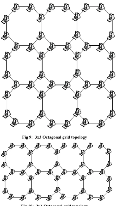
In the present work, authors proposed a new topological design for computer communication network in an efficient manner and to achieve desire accuracy in a minimum cost. The design is motivated from the circular ring topology which is taken in the form of octagon in which all nodes are placed at equidistant and lie on a circle as shown in figure. 6. Thereafter this ring is placed inside a grid of 1x1 on which eight computer systems are connected and placed at equidistance. The topological designs are extended for 2x2, 4x2, 3x3and 2x4 grids as shown in figure. 7, 8, 9, and 10, respectively. Simultaneously the design can be extended up to MxN mesh, where M and N are the grid number of rows and columns, respectively. The presented topology is noted as grid octagonal topology and the following definition is proposed.
Fig 6: 1x1 Octagonal grid topology
Fig 7: 2x2 Octagonal grid topology
[image:3.595.80.249.383.522.2]Fig 9: 3x3 Octagonal grid topology
Fig 10: 2x4 Octagonal grid topology
Definition (Grid Octagonal Topology)
Let us considered an integer set called as IN={M,N} then a graph G(V,E) is defined as per following sets of vertices (V) and edges (E)
2{2 * ( )}
V = M N+ M+N (1) { 1, 5} { 3, 7} { 2} { 4} { 6} { 8} E= E E U E E U E U E U E U E (2)
Edge set E, is manipulated by classifying it into several existing component level edge set groups of proposed octagonal topology which further have their own derived general formulae to count the number of edges. By the set union operation, these component edge set groups generate the main edge set E.
M=Number of Octagons in Rows; N=Number of Octagons in Columns;
D=Distance between opposite sides of Octagon; r= Length of each edge of Octagon;
By the use of above, one can construct the entire network of nodes attached under the distributed environment as shown in
node is busy then process is migrated to other node and uses the shared resources for execution of process.
4.
UML MODELING FOR PROCESS
EXECUTION IN OCTAGONAL GRID
NETWORK TOPOLOGY
4.1
UML Class Diagram
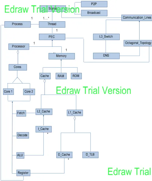
Communication in distributed computing environment takes place by message passing mechanism. Message get’s communicated among the node in the form of signals. Process execution is performed in a synchronized manner by implementing the thread concept. Proposed UML class model for the octagonal grid network topology is shown in figure. 11. In the figure, different classes are depicted and process is controlled by the Thread class which is attached to the PEC class used for the execution of a process. Synchronization is controlled by the Signal class and according to point to point (P2P class) or broadcast (Broadcast class), communication process is synchronized on the octagonal grid topology (Octagonal_Topology class) through communication lines (Communication_Lines class). Switching and message passing techniques are controlled by the L3_Switch and DNS classes. Since PEC is fully responsible for execution of a process therefore it is attached with Processor and Memory classes. Processor contains two cores namely Core1 and Core2 while Memory class is classified as Cache, RAM and ROM. Instructions of process are fetched by I_Cache class associated to L2_Cache while data is controlled by D_Cache associated with L1_Cache. D_TLB class is a data translation lookaside buffer class. Instructions are first fetched then decoded, executed finally write back by using Fetch, Decode, ALU and Register classes, respectively. Finally the resultant is stored into Register class and linked to the Process class. The UML class model is the static structure which is depicting the various classes responsible for execution of process.
4.2
UML Sequence Diagram
Fig 12: UML sequence diagram for process execution in octagonal grid network topology
5.
PROPERTIES OF PROPOSED
TOPOLOGY
The proposed octagonal topologies have some of the important properties as stated below.
(a) Dedicated Link: - Dedicated point-to-point connection with only two devices on either side of node at the exterior layer of the octagonal topology and with three devices on either side of each node at the internal layer. Dedicated link guarantees that each connection carry its own data load, thus eliminating the traffic problem.
(b) Advantageous towards security and privacy. When the message travels the link only the user intended for it sees the message others are prevented from seeing the messages because of the physical boundaries of network.
(c) Robust: If one link becomes unusable it does not incapacitate the entire network. The traffic can be diverted easily.
(d) Easy to install and reconfigure, a layer of connected computer octagons can be easily installed. It is fully
suitable for large networks. There is no need to break the whole running network, whenever there is need of addition or deletion of any octagonal structure in the octagonal network.
(e) Only two I/O ports for interconnection at exterior layer of octagonal topology and three I/O ports at the interior layer of network architecture is required for creating the proposed network architecture.
(f) Cabling the proposed topology is easy and its measure is also easily possible by using mathematical formula derived for edge calculations of the network architecture.
(g) Physically the departmental clustering can also be done easily.
6.
SPACE COMPLEXITY
For the octagonal grid topology, space complexity is computed for growing network. The computed data is recorded in table 1 which shows the number of grids formed in the proposed topology. The space complexity for 1x1, 2x2, 3x3, etc. is summarized in the table. It is observed that as variation of grids in the proposed octagonal topology occurs, the space complexity also increases in a linear order. The general formula for the space complexity is given below:
Space Complexity S
If M>N S=(3*M+N) (3)
If M<N S=(3*N+M) (4) The space complexity of the above octagonal grid network toplogy is of linear order.
The graphical presentation of the space complexity with grid numbers is represented in figure 13. Results are obtained by increasing the number of grids and it is observed that as one octagon grid is increased, the space complexity also increases according to equations 3 and 4.
0 2 4 6 8 10 12 14 16 18
1 2 4 3 6 9 4 8 12 16
Number of Grids in Proposed Topology
[image:7.595.39.294.274.514.2]S p a c e C o m p le x it y Space Complexity
Fig. 13. Space complexity Vs Number of grids.
7.
CONCLUSIONS
From the above work, it is concluded that the grid octagonal topology is a very effective topology for static interconnection of the computer systems under the distributed environment even one can connect the multiple handheld devices inside the one grid. As the grid grows, the numbers of attached computer systems also grow with linearly varying space complexity. The drawback of the proposed approach is that if one grid fails then eight computer systems or devices will not work while the remaining devices attached in the row and column grids shall work. The proposed research work may be further extended in many directions and one of the most promising direction is to search the optimal path when the grid becomes complex.
8.
REFERENCES
[1] K. Hwang, Advance Computer Architecture, 4th ed, Tata McGraw Hill, Reprint 2004, pp. 80-88.
[2] M. Wahlisch, Modeling the Network Topology, In Modeling and Tools for Network Simulation, Heidelberg: Springer, 2010, pp. 471-486.
[3] S. Latha and S.K. Srivatsa, On Some Aspects of Design of Cheapest Survivable Networks, IJCSNS International Journal of Computer Science and Network Security, Vol.7 No.11, November 2007.
[4] V.N. Kamalesh and S.K. Srivatsa, On the Assignment of Node Number in a Computer Communication Network, Proceedings of the World Congress on Engineering and Computer Science 2008, WCECS 2008, October 22 - 24, 2008, San Francisco, USA.
[5] V.N. Kamalesh and S.K. Srivatsa, On the Design of Minimum Cost Survivable Network Topologies, NCC 2009, January 16-18,IIT Guwahati.
[6] C. Ersoy and S.S. Panwar, Topological Design of Interconnected LAN/MAN Network, IEEE Journal Selected Areas in Communications, Vol 11, No. 8 October 1993.
[7] T. Takabatake, K. Kaneko and H. Ito, HCC Generalized Hierarchical Completely- Connected Networks, IEICE TRANS. INF. & SYST., Vol. E83-D, NO.6 June 2000.
[8] M.L. Liu, Distributed Computing Principles and Applications, Pearson Education, 2003, pp. 25-26.
[9] A.S. Tanenbaum,, Distributed Operating Systems, Prentice Hall, 1995.
[10]A. Siberschatz , P. B. Galvin, Operating Systems Concepts, 5th ed, John Wiley & Sons, Inc, 2000.
[11]M. Milenkovic, Operating Systems Concepts and Design, Tata Mcgraw-Hill, 1997, pp. 46-58.
[12]L. Lamport,, Event ordering and time clock scheduling mechanism in a Distributed Computing Systems, Communications of the ACM, vol.21, no. 7, July 1978, pp. 558-565.
[13]L. Lamport, Time, Clocks, and the Ordering of Events in a Distributed System, Communications of the ACM, Volume 21 Number 7, July 1978.
[14]E. Levy, G Louchard and J. Petit, A Distributed Algorithm to Find Hamiltonian Cycles in G(n, p) Random Graphs, This research was partially supported by the EU within the 6th Framework Programme under TABLEI
SPACE COMPLEXITY FOR OCTAGONAL GRID NETWORK TOPOLOGY
S. No. M N M*N No. of Nodes 2[2M*N + M+N]
Space Complexity (3*M + N) 0r(3*N+M)
1 1 1 1 8 4
2 2 1 2 14 7
3 2 2 4 24 8
4 3 1 3 20 10
5 3 2 6 34 11
6 3 3 9 48 12
7 4 1 4 26 13
8 4 2 8 52 14
9 4 3 12 62 15
Modeling Performance Oriented Applications. In <<UML>>, Model Engineering Concepts and Tools, Springer-Verlag., Dresden, Germany 2002.
[16]S. Pllana and T. Fahringer, UML-based Modeling of Performance-oriented Parallel and Distributed Applications. Proceedings of the Winter Simulation Conference, Vol. 1, Issue. 8–11, Dec. 2002, pp 497–505.
[17]OMG, 2001, Unified Modeling Language Specification. Available: http://www.omg.org. (Accessed on 15th Jan. 2012).
[18]OMG, 2002, OMG XML Metadata Interchange (XMI) Specification. Available: http://www.omg.org. (Accessed on 15th Jan 2012).
[20]G. Booch, J. Rumbaugh and I.Jacobson, The Unified Modeling Language User Guide, Twelfth Indian Reprint, Pearson, 2004.
[21]V. Saxena, D. Arora and S. Ahmad, Object-oriented Distributed Architecture System through UML. In Proceedings of the IEEE International Conference on Advances in Computer Vision and Information Technology, Aurangabad (MS), India Nov. 28-30, 2007, ISBN 978-81-89866-74-7, pp. 305-310.