2016 International Conference on Manufacturing Science and Information Engineering (ICMSIE 2016) ISBN: 978-1-60595-325-0
Tool Wear Research And Milling Parameter
Optimization During High-Speed Milling
3Cr2Mo
BO SUN, JINJIANG CHEN, SHILONG JIAO, FANG WANG
and GUANGWEI TIAN
ABSTRACT
This paper focuses on the copy measurement to measure radial wear of ball end mill. Then, the model of tool wear was established through tool wear test. The results of experiment show that the model is of higher precision and is useful to predict the amount of wear. Finally, a milling process optimization model was proposed by maximizing efficiency and minimizing cost targets. In addition, we aimed to get the reasonable high speed milling parameters by choosing non-dominated sorting genetic algorithm II (NSGA- II) to solve the model.1
INTRODUCTION
High Speed Milling is a highly advanced manufacturing technology characterized by high efficiency and high precision. It improves the efficiency of mold manufacturing. In the process of high speed milling there are some research progress in tool wear and optimization milling parameters. Senthil Kumar, A., etc. [1] established the model of tool wear and time variable, tool wear experiment was carried out by stainless steel (SS410), determined tool wear empirical formula by multiple linear regression. The United States, Germany and Sweden and other countries except for specific milling process parameters optimization [2,3], has formed the adaptability good cutting database. However, tool performance has failed
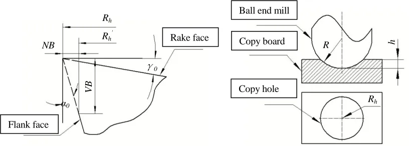
Figure 1. Relationship between VB and NB. Figure 2. Copy tool radius.
[image:2.612.77.485.77.223.2]
Figure 3. Contour circle image. Figure 4.Experimental setup.
to be fully played in the process of high speed milling of 3Cr2Mo steel mold, because there is little quantitative description of the method about the law of tool wear. Reasonable high speed milling parameters can’t be determined based on the traditional methods. In addition, the advantages of high speed milling can’t be fully taken according to the experience of milling parameters. Further research is still necessary in the study of tool wear on effective method of cutting parameters model. It’s also hoped that the manufacturing efficiency and the cost would be taken into consideration in the machining process. Thus, the method of multi-objective milling parameter optimization is of high value.
This paperextends the method of the copy measurementto measure radical wear of ball end mill. Tool wear model is established by experiment based on this method. Furthermore, the milling parameters optimization model is reported with the goal to maximize productivity and minimize the cost.
Rh
Rh
'
NB
α0
γ0
Rake face
Flank face
Ball end mill
Copy board
Copy hole
R
Rh
Copying plate Workpiece
VB
1. METHOD OF MEASUREMENT FOR WEAR
The tool wear is mainly measured by microscope measuring tool wear. However, the process of measurement is complicated and takes too long. This method could be more reasonable if they had taken the complication and time it takes into consideration. The purpose of this paper is to propose the copy measurement, which refers from the thought of “the milling cutter contour copy” [4].This method is to measure the amount of wear after the test to keep the continuity of the tool wear test process and shorten the test time.
The sectional radius of ball end millwill reduce from Rh to Rh '
after the milling process. As shown in Figure 1, the relationship between the flank wear width VB and sectional radius NB is as follows:
VB(RhRh') cot0 NBcot0 (1)
Known by the formula (1),there is a linear relationship VB and NB,and the widely applicable cutter life test standard of tool failure is the VB.Therefore, we choose NB as a cutting tool failure criterion instead of VB.
As is shown in Figure 2, mill two holes of the same depth before and after the experiment on duplicate plate respectively. The value difference of holes radius outline is the tool wear amount during the tool test. Then, measure the outline radius Rh using the image. The specific method is as follows: As is shown in Figure 3, take
pictures to get round hole profile image by using OLYMPUS OLS3100 laser confocal microscope copy hole camera. Afterwards, detect the edge of the circle contour by using the edge function provided by the software MATLAB. Furthermore, take 12 markers at the approximate average of the circumferential edge to get the circle radius value Rh by the least squares principle. The copy
measurement could measure tool wear continuously and improve the measurement efficiency.
2. TOOL WEAR MODELING AND EXPERIMENT
Machine tool: DMU 60 mono BLOCK CNC machining center. Cutter: OSK KM 2BRNL end mill.Work piece: pre-hardened 3Cr2Mo die steel plate.Copying plate: 3Cr2Mo die steel plate that the upper and lower surface is fine grinded and the upper surface is polished.Milling method: the plane is milled byreciprocating and equidistant tool path.Thecutting fluid is emulsion and the tool inclination angle is 15 °[5].
0.23 and 0.27 mm. 3 copied holes are milled in each test, The milling parameters of copied hole: The spindle speed is 2000 r/min, the feed rate of each tooth is 0.005mm/z.
TABLE I. ORTHOGONAL TEST FACTOR.
No.
Test factor
n(A) (r/min)
ap(B) (mm)
ae(c) (mm)
fz(D) (mm/z)
1 11000 0.03 0.05 0.04
2 14000 0.08 0.10 0.08
3 17000 0.13 0.15 0.12
[image:4.612.103.515.286.446.2]4 20000 0.18 0.20 0.16
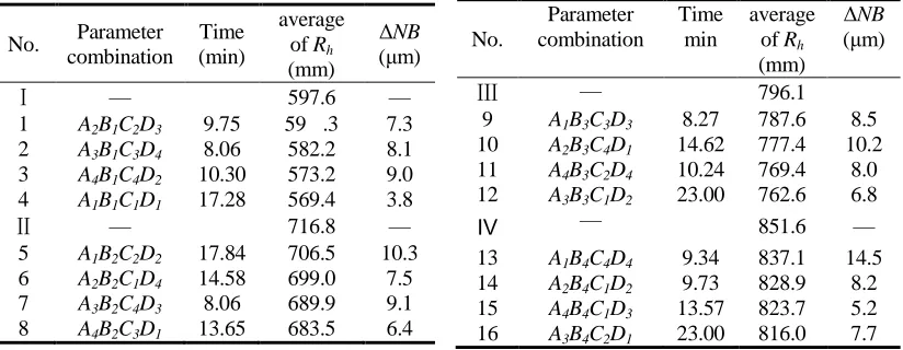
Table II. TOOL WEAR TEST RESULTS. Table II. (Continued)
No. Parameter combination
Time (min)
average of Rh (mm)
ΔNB
(μm)
Ⅰ — 597.6 —
1 A2B1C2D3 9.75 59 .3 7.3 2 A3B1C3D4 8.06 582.2 8.1 3 A4B1C4D2 10.30 573.2 9.0 4 A1B1C1D1 17.28 569.4 3.8
Ⅱ — 716.8 —
5 A1B2C2D2 17.84 706.5 10.3 6 A2B2C1D4 14.58 699.0 7.5 7 A3B2C4D3 8.06 689.9 9.1 8 A4B2C3D1 13.65 683.5 6.4
No. Parameter combination Time min average of Rh (mm)
ΔNB
(μm)
Ⅲ — 796.1
9 A1B3C3D3 8.27 787.6 8.5 10 A2B3C4D1 14.62 777.4 10.2 11 A4B3C2D4 10.24 769.4 8.0 12 A3B3C1D2 23.00 762.6 6.8
Ⅳ — 851.6 —
13 A1B4C4D4 9.34 837.1 14.5 14 A2B4C1D2 9.73 828.9 8.2 15 A4B4C1D3 13.57 823.7 5.2 16 A3B4C2D1 23.00 816.0 7.7
After the test, remove the copying plate. Copied holesˈ radius are measured by the method of copy measurement .The average of 3 copied holes date is shown in Table II.Suppose arbitrary section of the ball end mill is Rh, the radius is Rh1 as the
time of cutting is t1 and the radius is Rh2 as cutting continuing to t2 .During the period
of t2, the tool wear is supposed to be ΔNB :
2 1 ( h h2) ( h h1) h1 h2
NB NB NB R R R R R R
(2)
The index model of relationship between tool wear and milling parameters is written as follows:
NB Cn a a fp e z t
Where C is working condition of coefficient, is the spindle speed, apis the
depth of the milling, ae is the cutting width, fz is and the feed rate of each tooth, α
is spindle speed coefficient;β is milling depth coefficient, γ is milling width coefficient, δ is feed per tooth coefficient.
[image:5.612.98.498.219.292.2]Use multiple linear regression to solve the equations. The model of tool wear can be expressed as:
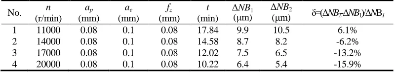
Table III. Verify The Correctness Of The Model Of Tool Wear.
No. n (r/min)
ap (mm)
ae (mm)
fz (mm)
t
(min)
ΔNB1
(μm)
ΔNB2
(μm) δ=(ΔNB2-ΔNB1)/ΔNB1 1 11000 0.08 0.1 0.08 17.84 9.9 10.5 6.1% 2 14000 0.08 0.1 0.08 14.58 8.7 8.2 -6.2% 3 17000 0.08 0.1 0.08 12.02 7.5 6.5 -13.2% 4 20000 0.08 0.1 0.08 10.22 6.4 5.4 -15.9%
2.39 0.237 0.032 0.754 0.549 0.898
10 p e z
NB n a a f t
(4)
It costs a lot of material and time to permit the tool wear test for taking tool life into consideration. It is a fast test method of tool life to use increment of tool wear and the model of milling parameters to acquire the equation of tool wear.
Suppose gauge wear NBT=60μm as the standard of cutter blunting. Take it into formula (4):
0.264 0.0356 0.840 0.611
0.209 p e z
T n a a f (5)
The formula (5) shows that using higher spindle speed and smaller milling depth, milling width and feed engagement in high speed milling of 3Cr2Mo die steel can increase the tool life.
In order to verify the correctness of the model of tool wear, use the parameters to permit milling test. As the results shown in Table III, relative error between the measured value and calculated with formula (5) is -15.9% to 6.1%. So the model has a higher accuracy and can be used for prediction of wear.
3. OPTIMIZATION OF MILLING PARAMETERS
The best optimization goal is the maximum productivity and the minimum cost of production in the process of metal cutting parameter optimization. The optimized
Processing time and processing parameters of the target parameters can be described as:
ts V zna a f/ p e z tz th (6)
Where V is volume of material to be removed, z is cutter tooth,tzis preparation
time, th is cutter change time,ts is processing time.
The objective function of production cost could be expressed as:
Cs C tm(mth)C tw(m tz th)Ct (7)
Where Cs is conversion cost, Cm is cost per unit time, Cw is wage costs per unit
time, tm is discretionary time. Ct is cutter cost.
By substituting formula (6) into formula (7), so the production cost of a process can be calculated as follows:
( / ) ( / ) /
s m p e z h w p e z z h m
C C V zna a f t C V zna a f t t t C T (8)
Through investigation, th=2min,tz =0.3min,Cm =2.7 yuan/min, Cw
=0.3yuan/min, C=200 yuan, V=1 000mm3, the tool life ofT is determined by the formula (5).
The objective function of processing time is expressed as:
f x1( )500 /x x x x1 2 3 42.3 (9)
The objective function of production cost is given as:
1 5 1.264 0.964 0.160 0.389 2( ) 1500( 1 2 3 4) 4.784 10 1 2 3 4 6.29
f x x x x x x x x x (10)
1 2 3 4
1 5 1.264 0.964 0.160 0.389
1 2 3 4 1 2 3 4
1 1 2 1 3 2
4 2 5
min ( ) 500 / 2.3
min ( ) 1500( ) 4.784 10 6.29
. . g ( ) 11000 0 g ( ) 20000 0 g ( ) 0.03 0
g ( ) 0.18 0 g ( ) 0.05
f x x x x x
f x x x x x x x x x
s t x x x x x x
x x x
3 6 3
7 4 8 4
2 4
9 3 1 4
0 g ( ) 0.20 0 (11)
g ( ) 0.04 0 g ( ) = 0.16 0
g ( ) 15.9 1.38 10 0.2834 0
x x x
x x x x
x x x x
In this paper, a genetic algorithm (NSGA- II) is used to solve the optimization problem of milling parameters.NSGA- II is a kind of multi-objective optimization algorithm, which uses a more rapid non inferiorityand the new diversity preserving strategy to improve the efficiency of computing.
[image:7.612.192.397.423.584.2]It is known that the value of the objective function decreases with the increase of milling parameter value. While the nonlinear constraints don’t involve x2.Therefore, the optimization is based on the maximal x2 (ap = 0.18 mm). The multi-objective optimization method is optimized to get the Pareto front end based on the theory of NSGA- II, as shown in Figure 5. The front of Pareto trends indicates the production cost varies more compared with the processing time in the AB part, while in the CD part, the production cost varies compared with the processing time. In consideration of both production efficiency and production cost, the set of BC parts of Pareto is expected to set. Extract BC partial Pareto solution is shown in table IV.
Figure 5. The front of Pareto.
C
28.62 28.66 28.70 28.74
P ro ce ss in g co st (y ua n)
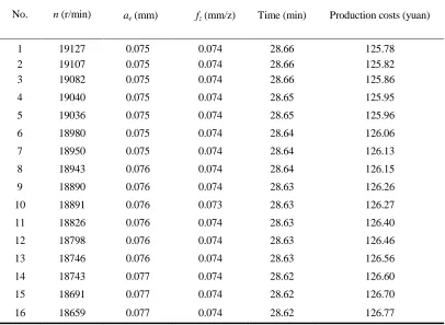
TABLE IV. PARETO FRONT END BC PART OF THE CORRESPONDING PARAMETERS.
No. n (r/min) ae (mm) fz (mm/z) Time (min) Production costs (yuan)
1 19127 0.075 0.074 28.66 125.78 2 19107 0.075 0.074 28.66 125.82 3 19082 0.075 0.074 28.66 125.86
4 19040 0.075 0.074 28.65 125.95
5 19036 0.075 0.074 28.65 125.96
6 18980 0.075 0.074 28.64 126.06
7 18950 0.075 0.074 28.64 126.13
8 18943 0.076 0.074 28.64 126.15
9 18890 0.076 0.074 28.63 126.26
10 18891 0.076 0.073 28.63 126.27
11 18826 0.076 0.074 28.63 126.40
12 18798 0.076 0.074 28.63 126.46
13 18746 0.076 0.074 28.63 126.56
14 18743 0.077 0.074 28.62 126.60
15 18691 0.077 0.074 28.62 126.70
16 18659 0.077 0.074 28.62 126.77
Conclusions can be drawn as follows by analyzing the Pareto solution:
(1) The target function value (time and cost) of each solution is of little fluctuation, and the difference between the various solutions (milling parameter) is not much, which is due to the influence of the parameters variation on the processing time and the processing cost is the same within the scope of milling parameters.
(2) The machining cost can be reduced greatly by increasing the speed of the main shaft and reducing the width of the milling, while the processing efficiency reduces little scope.
4. CONCLUSIONS
(1)Thecopy measurement can be used to measure the radial wear of ball end mill.
spindle speed, the smaller milling depth, the cutting width and the feed rate of each tooth are suggested.
(3) Increase the spindle speed, reduce the milling width appropriately will greatly reduce the processing cost and the processing efficiency of little reduction. Take both the efficiency while cost of processing into account, it is appropriate to use high spindle speed, the appropriate large milling depth, the smaller the milling width and the feed per tooth.The better milling parameters range is as follows:the spindle speed is 18300~19300r/min, the depth of the milling is 0.18mm, the cutting width is 0.074~0.077mm, the feed rate of each tooth is 0.072~0.076mm/z. Recommended milling parameters are: the spindle speed is 18500r/min, the depth of the milling is 0.18mm, the cutting width is 0.07mm, the feed rate of each tooth is 0.08mm/z.The processing time is 29.11min, the processing cost is 127.99 yuan by using the recommended milling parameters.
REFERENCES
1. Senthil Kumar A, Raja Durai A, Sornakumar T. 2006. The Effect of Tool Wear on Tool Life of Alumina-based Ceramic Cutting Tools While Machining Hardened Martensitic Stainless Steel ,Journal of Materials Processing Technology,173, 151-156.
2. Wardany E I. 2009.Optimum Process Parameters to Produce Green Ceramic Complex Parts. Annals of CIRP, 58, 109-112.
3. Juan H. 2003. The Optimal Cutting-parameter Selection of Production Cost in HSM for EKD61 Tool Steels, International Journal of Machine Tools and Manufacture, 43, 679-686.
4. Zhang Chen. 2008. Modeling and Wear-induced Error Compensation of Ball-end Milling Cutter Wear, Journal of Mechanical Engineering, 44, 207-218.